2007 NISSAN TIIDA sensor
[x] Cancel search: sensorPage 4768 of 5883

COLLISION DIAGNOSIS
SR-25
< ON-VEHICLE REPAIR >
C
D
E
F
G
I
J
K
L
MA
B
SR
N
O
P
Part SRS is activated SRS is NOT activated
LH side curtain air
bag moduleIf the LH side curtain
air bag has deployed:
REPLACE the LH
side curtain air bag
module. (Repair the
center pillar inner, etc.
before installing new
one if damaged.)If the LH side curtain air bag has NOT deployed:
1. Check for visible signs of damage (dents, tears, deformation) of the center pillar
on the collision side.
2. If damaged—Remove the LH side curtain air bag module.
3. Check for visible signs of damaged (tears etc.) of the LH side curtain air bag mod-
ule.
4. Check harness and connectors for damage, and terminals for deformities.
5. If no damage is found, reinstall the LH side curtain air bag module with new fas-
teners.
6. If damaged—REPLACE the LH side curtain air bag module with new fasteners.
RH side curtain air
bag moduleIf the RH side curtain
air bag has deployed:
REPLACE the RH
side curtain air bag
module. (Repair the
center pillar inner, etc.
before installing new
one if damaged.)If the RH side curtain air bag has NOT deployed:
1. Check for visible signs of damage (dents, tears, deformation) of the center pillar
on the collision side.
2. If damaged—Remove the RH side curtain air bag module.
3. Check for visible signs of damaged (tears etc.) of the RH side curtain air bag
module.
4. Check harness and connectors for damage, and terminals for deformities.
5. If no damage is found, reinstall the RH side curtain air bag module with new fas-
teners.
6. If damaged—REPLACE the RH side curtain air bag module with new fasteners.
Front LH side air bag
moduleIf the front LH side air
bag has deployed:
REPLACE front LH
seatback assembly.If the front LH side air bag has NOT deployed:
1. Check for visible signs of damage (dents, tears, deformation) of the seat back on
the collision side.
2. Check harness and connectors for damage, and terminals for deformities.
3. If damaged—REPLACE the front LH seatback assembly.
Front RH side air bag
moduleIf the front RH side air
bag has deployed:
REPLACE front RH
seatback assembly.If the front RH side air bag has NOT deployed:
1. Check for visible signs of damage (dents, tears, deformation) of the seat back on
the collision side.
2. Check harness and connectors for damage, and terminals for deformities.
3. If damaged—REPLACE the front RH seatback assembly.
(LH or RH) side air
bag (satellite) sensor If any of the SRS
components have de-
ployed:
REPLACE the side air
bag (satellite) sensor
on the collision side
with new fasteners.
(Repair the center pil-
lar inner, etc. before
installing new one if
damaged.)If none of the SRS components have been activated:
1. Remove the side air bag (satellite) sensor on the collision side. Check harness
connectors for damage, terminals for deformities, and harness for binding.
2. Check for visible signs of damage (dents, cracks, deformation) of the side air bag
(satellite) sensor.
3. Install the side air bag (satellite) sensor to check fit.
4. If no damage is found, reinstall the side sir bag (satellite) sensor with new fasten-
ers.
5. If damaged—REPLACE the side air bag (satellite) sensor with new fasteners.
Diagnosis sensor unit If any of the SRS
components have de-
ployed:
REPLACE the diag-
nosis sensor unit with
new fasteners.If none of the SRS components have been activated:
1. Check case and bracket for dents, cracks or deformities.
2. Check connectors for damage, and terminals for deformities.
3. If no damage is found, reinstall the diagnosis sensor unit with new fasteners.
4. If damaged—REPLACE the diagnosis sensor unit with new fasteners.
Seat belt pre-tension-
er assemblies
(All applicable loca-
tions: buckle, reel, lap
outer)If either the driver or
passenger seat belt
pre-tensioner* has
been activated:
REPLACE all seat
belt pre-tensioner as-
semblies with new
fasteners.
*: Confirm seat belt
pre-tensioner activa-
tion using CONSULT-
III only.If the pre-tensioners have NOT been activated:
1. Remove seat belt pre-tensioners.
Check harness cover and connectors for damage, terminals for deformities, and
harness for binding.
2. Check belts for damage and anchors for loose mounting.
3. Check retractor for smooth operation.
4. Check seat belt adjuster for damage.
5. Check for deformities of the center pillar inner.
6. If the center pillar inner has no damage, REPLACE the seat belt pre-tensioner
assembly.
7. If no damage is found, reinstall seat belt pre-tensioner assembly.
8. If damaged—REPLACE. Install the seat belt pre-tensioners with new fasteners.
Page 4770 of 5883

SRC-1
RESTRAINTS
C
D
E
F
G
I
J
K
L
M
SECTION SRC
A
B
SRC
N
O
P
CONTENTS
SRS AIRBAG CONTROL SYSTEM
BASIC INSPECTION ....................................3
DIAGNOSIS AND REPAIR WORK FLOW .........3
Work Flow .................................................................3
INTERMITTENT INCIDENT .................................5
Inspection Procedure ...............................................5
Trouble Diagnosis with CONSULT-III .......................5
FUNCTION DIAGNOSIS ...............................6
SRS AIR BAG SYSTEM ......................................6
SRS Configuration ....................................................6
SRS Component Parts Location ...............................7
Driver Air Bag Module ...............................................7
Front Passenger Air Bag Module ..............................8
Passenger Air Bag Deactivation Switch ....................8
Front Side Air Bag .....................................................8
Side Curtain Air Bag ..................................................8
Seat Belt Warning Lamp Control Unit .......................9
Seat Belt Pre-tensioners ...........................................9
Direct-connect SRS Component Connectors ............9
ON BOARD DIAGNOSTIC (OBD) SYSTEM ......11
Trouble Diagnosis Introduction ...............................11
SRS Operation Check .............................................11
Trouble Diagnosis without CONSULT-III ................13
CONSULT-III Function (AIR BAG) ..........................13
Self-Diagnosis Function (Without CONSULT-III) ....13
COMPONENT DIAGNOSIS .........................15
B1049 - B1052 DRIVER AIR BAG MODULE ....15
Description ..............................................................15
DTC Logic ...............................................................15
Diagnosis Procedure (Component diagnosis) ......16
B1065 - B1068 PASSENGER AIR BAG MOD-
ULE .....................................................................
18
Description ..............................................................18
DTC Logic ...............................................................18
Diagnosis Procedure (Component diagnosis) ......19
B1134 – B1137 SIDE AIRBAG MODULE LH ...21
Description ...............................................................21
DTC Logic ................................................................21
Diagnosis Procedure (Component diagnosis) .......22
B1129 – B1132 SIDE AIRBAG MODULE RH ...24
Description ...............................................................24
DTC Logic ................................................................24
Diagnosis Procedure (Component diagnosis) .......25
B1150 – B1153 SIDE CURTAIN AIR BAG
MODULE LH .....................................................
27
Description ...............................................................27
DTC Logic ................................................................27
Diagnosis Procedure (Component diagnosis) .......28
B1145 – B1148 SIDE CURTAIN AIR BAG
MODULE RH .....................................................
30
Description ...............................................................30
DTC Logic ................................................................30
Diagnosis Procedure (Component diagnosis) .......31
B1086 – B1089 SEAT BELT PRE-TENSION-
ER LH ................................................................
33
Description ...............................................................33
DTC Logic ................................................................33
Diagnosis Procedure (Component diagnosis) .......34
B1182 - B1185 LAP SEAT BELT PRE-TEN-
SIONER .............................................................
36
Description ...............................................................36
DTC Logic ................................................................36
Diagnosis Procedure (Component diagnosis) .......37
B1081 – B1084 SEAT BELT PRE-TENSION-
ER RH ................................................................
39
Description ...............................................................39
DTC Logic ................................................................39
Diagnosis Procedure (Component diagnosis) .......40
B1033 – B1035 CRASH ZONE SENSOR .........42
Description ...............................................................42
Page 4771 of 5883

SRC-2
DTC Logic ...............................................................42
Diagnosis Procedure (Component diagnosis) ......43
B1118 – B1120 SATELLITE SENSOR LH ........45
Description ..............................................................45
DTC Logic ...............................................................45
Diagnosis Procedure (Component diagnosis) ......46
B1113 – B1115 SATELLITE SENSOR RH .......48
Description ..............................................................48
DTC Logic ...............................................................48
Diagnosis Procedure (Component diagnosis) ......49
B1XXX AIR BAG DIAGNOSIS SENSOR UNIT ...51
Description ..............................................................51
DTC Logic ...............................................................51
Diagnosis Procedure (Component diagnosis) ......52
B1209 – B1210 COLLISION DETECTION ........54
Description ..............................................................54
DTC Logic ...............................................................54
Diagnosis Procedure (Component diagnosis) ......54
SEAT BELT WARNING LAMP CONTROL
UNIT ...................................................................
55
Power Supply and Ground Circuit Check for Seat
Belt Warning Lamp Control Unit .............................
55
Seat Belt Buckle Switch Circuit Check ...................55
ECU DIAGNOSIS .......................................58
DIAGNOSIS SENSOR UNIT .............................58
Reference Value .....................................................58
Wiring Diagram — RHD Models — .........................59
Wiring Diagram — LHD Models — .........................68
Trouble Diagnosis with CONSULT-III .....................76
Trouble Diagnosis without CONSULT-III ................78
SYMPTOM DIAGNOSIS ............................82
SRS AIR BAG SYSTEM ....................................82
Symptom Table .......................................................82
Air Bag Warning Lamp Does Not Turn On ..............82
Air Bag Warning Lamp Does Not Turn Off ..............82
Seat Belt Warning Lamp Does Not Turn On ...........83
Seat Belt Warning Lamp Does Not Turn Off ...........84
PRECAUTION ............................................86
PRECAUTIONS .................................................86
Precaution for Supplemental Restraint System
(SRS) "AIR BAG" and "SEAT BELT PRE-TEN-
SIONER" .................................................................
86
Precaution for SRS "AIR BAG" and "SEAT BELT
PRE-TENSIONER" Service ....................................
86
Page 4775 of 5883

SRC-6
< FUNCTION DIAGNOSIS >
SRS AIR BAG SYSTEM
FUNCTION DIAGNOSIS
SRS AIR BAG SYSTEM
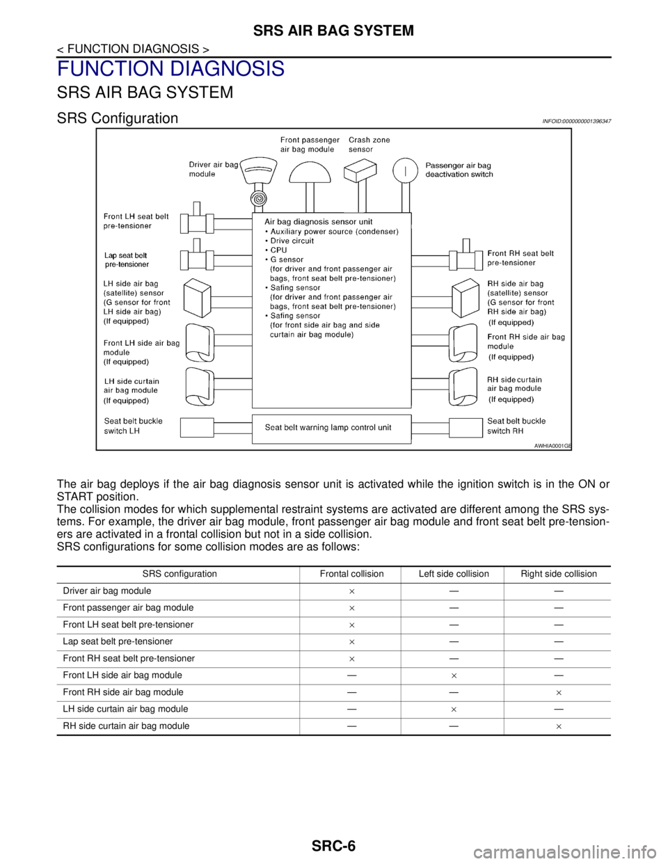
SRS ConfigurationINFOID:0000000001396347
The air bag deploys if the air bag diagnosis sensor unit is activated while the ignition switch is in the ON or
START position.
The collision modes for which supplemental restraint systems are activated are different among the SRS sys-
tems. For example, the driver air bag module, front passenger air bag module and front seat belt pre-tension-
ers are activated in a frontal collision but not in a side collision.
SRS configurations for some collision modes are as follows:
AWHIA0001GB
SRS configuration Frontal collision Left side collision Right side collision
Driver air bag module×——
Front passenger air bag module×——
Front LH seat belt pre-tensioner×——
Lap seat belt pre-tensioner×——
Front RH seat belt pre-tensioner×——
Front LH side air bag module —×—
Front RH side air bag module — —×
LH side curtain air bag module —×—
RH side curtain air bag module — —×
Page 4776 of 5883

SRS AIR BAG SYSTEM
SRC-7
< FUNCTION DIAGNOSIS >
C
D
E
F
G
I
J
K
L
MA
B
SRC
N
O
P
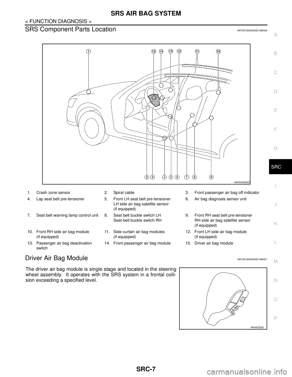
SRS Component Parts LocationINFOID:0000000001396420
Driver Air Bag ModuleINFOID:0000000001396421
The driver air bag module is single stage and located in the steering
wheel assembly. It operates with the SRS system in a frontal colli-
sion exceeding a specified level.
1. Crash zone sensor 2. Spiral cable 3. Front passenger air bag off indicator
4. Lap seat belt pre-tensioner 5. Front LH seat belt pre-tensioner
LH side air bag satellite sensor
(if equipped)6. Air bag diagnosis sensor unit
7. Seat belt warning lamp control unit 8. Seat belt buckle switch LH
Seat belt buckle switch RH9. Front RH seat belt pre-tensioner
RH side air bag satellite sensor
(if equipped)
10. Front RH side air bag module
(if equipped)11. Side curtain air bag modules
(if equipped)12. Front LH side air bag module
(if equipped)
13. Passenger air bag deactivation
switch14. Front passenger air bag module 15. Driver air bag module
AWHIA0002ZZ
WHIA0325E
Page 4781 of 5883
![NISSAN TIIDA 2007 Service Repair Manual SRC-12
< FUNCTION DIAGNOSIS >
ON BOARD DIAGNOSTIC (OBD) SYSTEM
SRS Air bag warning lamp examples
DIAGNOSTIC PROCEDURE 2
1. Connect CONSULT-III.
2. Diagnostic code is displayed on "SELF-DIAG [CURRENT]" NISSAN TIIDA 2007 Service Repair Manual SRC-12
< FUNCTION DIAGNOSIS >
ON BOARD DIAGNOSTIC (OBD) SYSTEM
SRS Air bag warning lamp examples
DIAGNOSTIC PROCEDURE 2
1. Connect CONSULT-III.
2. Diagnostic code is displayed on "SELF-DIAG [CURRENT]"](/manual-img/5/57395/w960_57395-4780.png)
SRC-12
< FUNCTION DIAGNOSIS >
ON BOARD DIAGNOSTIC (OBD) SYSTEM
SRS Air bag warning lamp examples
DIAGNOSTIC PROCEDURE 2
1. Connect CONSULT-III.
2. Diagnostic code is displayed on "SELF-DIAG [CURRENT]".
If no malfunction is detected on "SELF-DIAG [CURRENT]", but malfunction is detected in "SRS Operation
Check" using the "AIR BAG" warning lamp, the following cases may exist:
"SELF-DIAG [PAST]" memory might not be erased.
The SRS system malfunctions intermittently.
Perform DIAGNOSTIC PROCEDURE 4. Refer to SRC-13, "
Self-Diagnosis Function (Without CONSULT-
III)".
“AIR BAG” warning lamp (User mode) SRS condition Reference item
No malfunction is detected.
No further action is necessary.—
The system is malfunctioning and
needs to be repaired as indicated.Proceed to DIAGNOSTIC PROCE-
DURE 2 that follows (with CON-
SULT-III) or SRC-13, "
Trouble
Diagnosis without CONSULT-III"
(without CONSULT-III).
Air bag is deployed.
Seat belt pre-tensioner is deployed.Proceed to COLLISION DIAGNO-
SIS SR-23, "
For Frontal Collision" or
SR-24, "
For Side and Rollover Colli-
sion".
Air bag diagnosis sensor unit is mal-
functioning.
Air bag power supply circuit is mal-
functioning.
SRS air bag warning lamp circuit is
malfunctioning.Refer to SRC-82, "
Air Bag Warning
Lamp Does Not Turn Off".
Air bag diagnosis sensor unit is mal-
functioning.
Air bag warning lamp circuit is mal-
functioning.Refer to SRC-82, "
Air Bag Warning
Lamp Does Not Turn On".
SHIA0011E
SHIA0012E
SHIA0013E
SHIA0014E
Page 4782 of 5883

ON BOARD DIAGNOSTIC (OBD) SYSTEM
SRC-13
< FUNCTION DIAGNOSIS >
C
D
E
F
G
I
J
K
L
MA
B
SRC
N
O
P
Trouble Diagnosis without CONSULT-IIIINFOID:0000000001396362
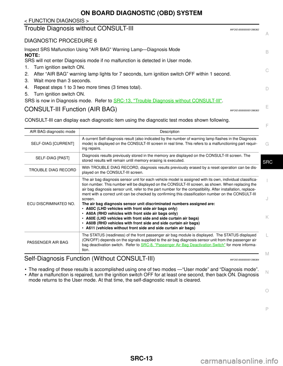
DIAGNOSTIC PROCEDURE 6
Inspect SRS Malfunction Using "AIR BAG" Warning Lamp—Diagnosis Mode
NOTE:
SRS will not enter Diagnosis mode if no malfunction is detected in User mode.
1. Turn ignition switch ON.
2. After “AIR BAG” warning lamp lights for 7 seconds, turn ignition switch OFF within 1 second.
3. Wait more than 3 seconds.
4. Repeat steps 1 to 3 two more times (3 times total).
5. Turn ignition switch ON.
SRS is now in Diagnosis mode. Refer to SRC-13, "
Trouble Diagnosis without CONSULT-III".
CONSULT-III Function (AIR BAG)INFOID:0000000001396363
CONSULT-III can display each diagnostic item using the diagnostic test modes shown following.
Self-Diagnosis Function (Without CONSULT-III)INFOID:0000000001396364
The reading of these results is accomplished using one of two modes —“User mode” and “Diagnosis mode”.
After a malfunction is repaired, turn the ignition switch OFF for at least one second, then back ON. Diagnosis
mode returns to the User mode. At that time, the self-diagnostic result is cleared.
AIR BAG diagnostic mode Description
SELF-DIAG [CURRENT]A current Self-diagnosis result (also indicated by the number of warning lamp flashes in the Diagnosis
mode) is displayed on the CONSULT-III screen in real time. This refers to a malfunctioning part requir-
ing repairs.
SELF-DIAG [PAST]Diagnosis results previously stored in the memory are displayed on the CONSULT-III screen. The
stored results will remain until memory erasing is executed.
TROUBLE DIAG RECORDWith TROUBLE DIAG RECORD, diagnosis results previously erased by a reset operation can be dis-
played on the CONSULT-III screen.
ECU DISCRIMINATED NO.The air bag diagnosis sensor unit for each vehicle model is assigned with its own, individual classifica-
tion number. This number will be displayed on the CONSULT-III screen, as shown. When replacing the
air bag diagnosis sensor unit, refer to the part number for the compatibility. After installation, replace-
ment with a correct unit can be checked by confirming this classification number on the CONSULT-III
screen.
The air bag diagnosis sensor unit discriminated numbers assigned are:
A60C (LHD vehicles with front side air bags only)
A60A (RHD vehicles with front side air bags only)
A60E (LHD vehicles with front side and side curtain air bags)
A60B (RHD vehicles with front side and side curtain air bags)
A611 (vehicles without front side and side curtain air bags)
PASSENGER AIR BAGThe STATUS (readiness) of the front passenger air bag module is displayed. The STATUS displayed
(ON/OFF) depends on the signals supplied to the air bag diagnosis sensor unit from the passenger air
bag deactivation switch. Refer to SRC-8, "
Passenger Air Bag Deactivation Switch" for more informa-
tion.
Page 4784 of 5883

B1049 - B1052 DRIVER AIR BAG MODULE
SRC-15
< COMPONENT DIAGNOSIS >
C
D
E
F
G
I
J
K
L
MA
B
SRC
N
O
P
COMPONENT DIAGNOSIS
B1049 - B1052 DRIVER AIR BAG MODULE
DescriptionINFOID:0000000001396365
DTC B1049 – B1052 DRIVER AIRBAG MODULE
The driver air bag module is single stage and wired to the air bag diagnosis sensor unit through the spiral
cable. The air bag diagnosis sensor unit will monitor for opens and shorts in detected lines to the driver air
bag module including the spiral cable.
PA R T L O C AT I O N
Refer to SRC-7, "SRS Component Parts Location".
DTC LogicINFOID:0000000001396366
DTC DETECTION LOGIC
With CONSULT-lll
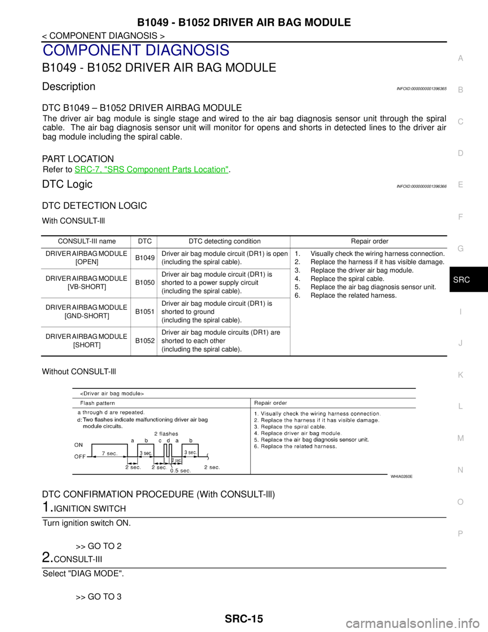
Without CONSULT-lll
DTC CONFIRMATION PROCEDURE (With CONSULT-lll)
1.IGNITION SWITCH
Turn ignition switch ON.
>> GO TO 2
2.CONSULT-III
Select "DIAG MODE".
>> GO TO 3
CONSULT-III name DTC DTC detecting condition Repair order
DRIVER AIRBAG MODULE
[OPEN]B1049Driver air bag module circuit (DR1) is open
(including the spiral cable).1. Visually check the wiring harness connection.
2. Replace the harness if it has visible damage.
3. Replace the driver air bag module.
4. Replace the spiral cable.
5. Replace the air bag diagnosis sensor unit.
6. Replace the related harness. DRIVER AIRBAG MODULE
[VB-SHORT]B1050Driver air bag module circuit (DR1) is
shorted to a power supply circuit
(including the spiral cable).
DRIVER AIRBAG MODULE
[GND-SHORT]B1051Driver air bag module circuit (DR1) is
shorted to ground
(including the spiral cable).
DRIVER AIRBAG MODULE
[SHORT]B1052Driver air bag module circuits (DR1) are
shorted to each other
(including the spiral cable).
WHIA0260E