2007 NISSAN TIIDA sensor
[x] Cancel search: sensorPage 4374 of 5883

MWI
BCM (BODY CONTROL MODULE)
MWI-67
< ECU DIAGNOSIS >
C
D
E
F
G
H
I
J
K
L
MB A
O
P
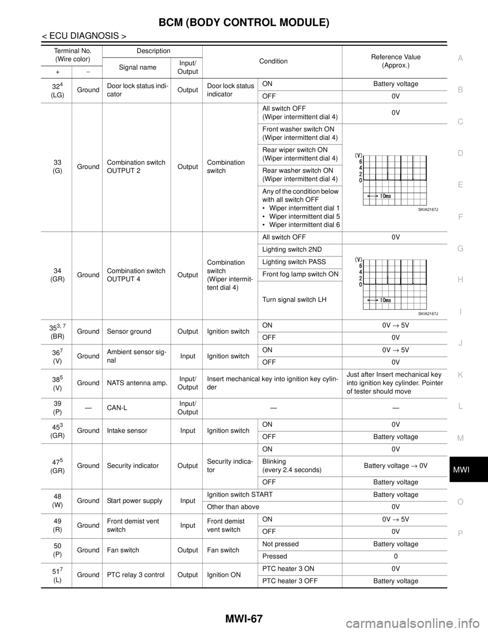
324
(LG)GroundDoor lock status indi-
catorOutputDoor lock status
indicatorON Battery voltage
OFF 0V
33
(G)GroundCombination switch
OUTPUT 2OutputCombination
switchAll switch OFF
(Wiper intermittent dial 4)0V
Front washer switch ON
(Wiper intermittent dial 4)
Rear wiper switch ON
(Wiper intermittent dial 4)
Rear washer switch ON
(Wiper intermittent dial 4)
Any of the condition below
with all switch OFF
Wiper intermittent dial 1
Wiper intermittent dial 5
Wiper intermittent dial 6
34
(GR)GroundCombination switch
OUTPUT 4OutputCombination
switch
(Wiper intermit-
tent dial 4)All switch OFF 0V
Lighting switch 2ND
Lighting switch PASS
Front fog lamp switch ON
Turn signal switch LH
35
3, 7
(BR)Ground Sensor ground Output Ignition switchON 0V → 5V
OFF 0V
36
7
(V)GroundAmbient sensor sig-
nalInput Ignition switchON 0V → 5V
OFF 0V
38
5
(V)Ground NATS antenna amp.Input/
OutputInsert mechanical key into ignition key cylin-
derJust after Insert mechanical key
into ignition key cylinder. Pointer
of tester should move
39
(P)—CAN-LInput/
Output——
45
3
(GR)Ground Intake sensor Input Ignition switchON 0V
OFF Battery voltage
47
5
(GR)Ground Security indicator OutputSecurity indica-
torON 0V
Blinking
(every 2.4 seconds)Battery voltage → 0V
OFF Battery voltage
48
(W)Ground Start power supply InputIgnition switch START Battery voltage
Other than above 0V
49
(R)GroundFront demist vent
switchInputFront demist
vent switchON 0V → 5V
OFF 0V
50
(P)Ground Fan switch Output Fan switchNot pressed Battery voltage
Pressed 0
51
7
(L)Ground PTC relay 3 control Output Ignition ONPTC heater 3 ON 0V
PTC heater 3 OFF Battery voltage Terminal No.
(Wire color)Description
ConditionReference Value
(Approx.)
Signal nameInput/
Output +−
SKIA2167J
SKIA2167J
Page 4375 of 5883

MWI-68
< ECU DIAGNOSIS >
BCM (BODY CONTROL MODULE)
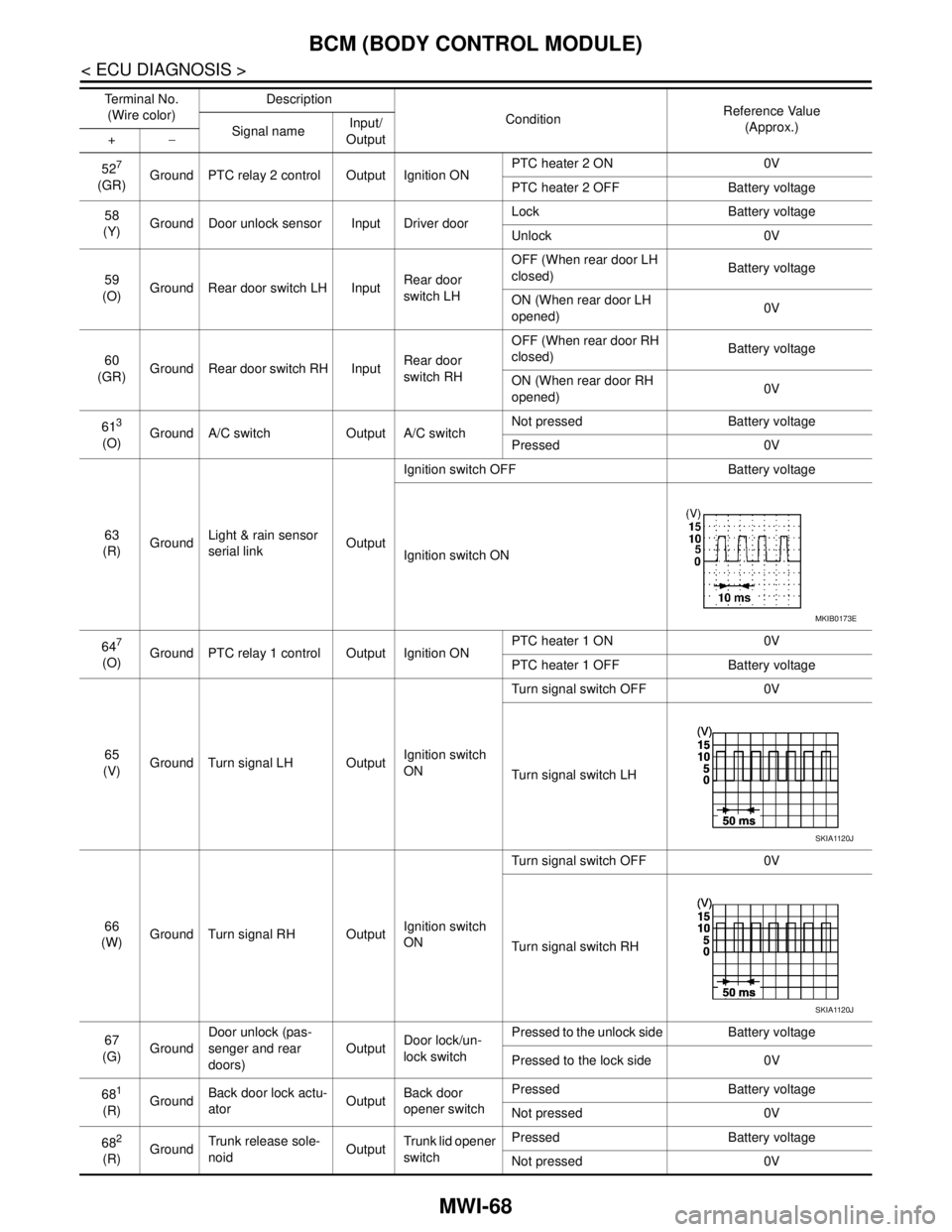
527
(GR)Ground PTC relay 2 control Output Ignition ONPTC heater 2 ON 0V
PTC heater 2 OFF Battery voltage
58
(Y)Ground Door unlock sensor Input Driver doorLock Battery voltage
Unlock 0V
59
(O)Ground Rear door switch LH InputRear door
switch LHOFF (When rear door LH
closed) Battery voltage
ON (When rear door LH
opened)0V
60
(GR)Ground Rear door switch RH InputRear door
switch RHOFF (When rear door RH
closed) Battery voltage
ON (When rear door RH
opened)0V
61
3
(O)Ground A/C switch Output A/C switchNot pressed Battery voltage
Pressed 0V
63
(R)GroundLight & rain sensor
serial linkOutputIgnition switch OFF Battery voltage
Ignition switch ON
64
7
(O)Ground PTC relay 1 control Output Ignition ONPTC heater 1 ON 0V
PTC heater 1 OFF Battery voltage
65
(V)Ground Turn signal LH OutputIgnition switch
ONTurn signal switch OFF 0V
Turn signal switch LH
66
(W)Ground Turn signal RH OutputIgnition switch
ONTurn signal switch OFF 0V
Turn signal switch RH
67
(G)GroundDoor unlock (pas-
senger and rear
doors)OutputDoor lock/un-
lock switchPressed to the unlock side Battery voltage
Pressed to the lock side 0V
68
1
(R)GroundBack door lock actu-
atorOutputBack door
opener switchPressed Battery voltage
Not pressed 0V
68
2
(R)GroundTrunk release sole-
noidOutputTrunk lid opener
switchPressed Battery voltage
Not pressed 0V Te r m i n a l N o .
(Wire color)Description
ConditionReference Value
(Approx.)
Signal nameInput/
Output +−
MKIB0173E
SKIA1120J
SKIA1120J
Page 4394 of 5883

MWI
THE FUEL GAUGE POINTER DOES NOT MOVE
MWI-87
< SYMPTOM DIAGNOSIS >
C
D
E
F
G
H
I
J
K
L
MB A
O
P
SYMPTOM DIAGNOSIS
THE FUEL GAUGE POINTER DOES NOT MOVE
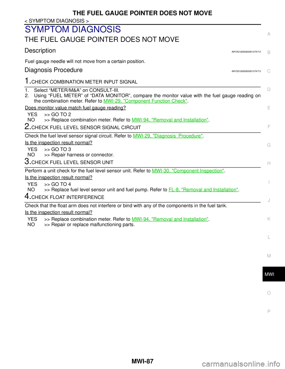
DescriptionINFOID:0000000001374712
Fuel gauge needle will not move from a certain position.
Diagnosis ProcedureINFOID:0000000001374713
1.CHECK COMBINATION METER INPUT SIGNAL
1. Select “METER/M&A” on CONSULT-III.
2. Using “FUEL METER” of “DATA MONITOR”, compare the monitor value with the fuel gauge reading on
the combination meter. Refer to MWI-29, "
Component Function Check".
Does monitor value match fuel gauge reading?
YES >> GO TO 2
NO >> Replace combination meter. Refer to MWI-94, "
Removal and Installation".
2.CHECK FUEL LEVEL SENSOR SIGNAL CIRCUIT
Check the fuel level sensor signal circuit. Refer to MWI-29, "
DiagnosisProcedure".
Is the inspection result normal?
YES >> GO TO 3
NO >> Repair harness or connector.
3.CHECK FUEL LEVEL SENSOR UNIT
Perform a unit check for the fuel level sensor unit. Refer to MWI-30, "
Component Inspection".
Is the inspection result normal?
YES >> GO TO 4
NO >> Replace fuel level sensor unit and fuel pump. Refer to FL-8, "
Removal and Installation".
4.CHECK FLOAT INTERFERENCE
Check that the float arm does not interfere or bind with any of the components in the fuel tank.
Is the inspection result normal?
YES >> Replace combination meter. Refer to MWI-94, "Removal and Installation".
NO >> Repair or replace malfunctioning parts.
Page 4398 of 5883

MWI
THE AMBIENT TEMPERATURE DISPLAY IS INCORRECT
MWI-91
< SYMPTOM DIAGNOSIS >
C
D
E
F
G
H
I
J
K
L
MB A
O
P
THE AMBIENT TEMPERATURE DISPLAY IS INCORRECT
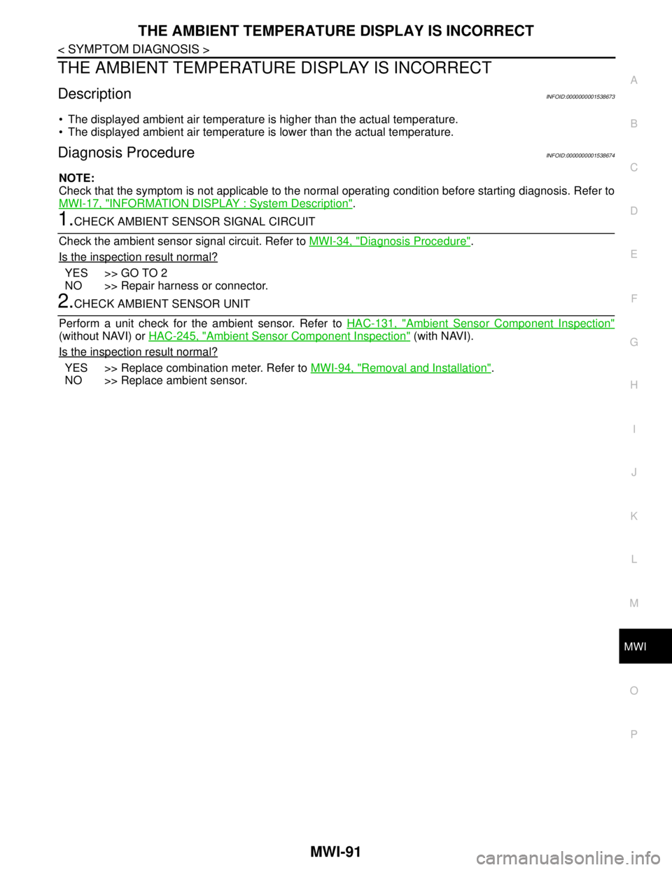
DescriptionINFOID:0000000001538673
The displayed ambient air temperature is higher than the actual temperature.
The displayed ambient air temperature is lower than the actual temperature.
Diagnosis ProcedureINFOID:0000000001538674
NOTE:
Check that the symptom is not applicable to the normal operating condition before starting diagnosis. Refer to
MWI-17, "
INFORMATION DISPLAY : System Description".
1.CHECK AMBIENT SENSOR SIGNAL CIRCUIT
Check the ambient sensor signal circuit. Refer to MWI-34, "
Diagnosis Procedure".
Is the inspection result normal?
YES >> GO TO 2
NO >> Repair harness or connector.
2.CHECK AMBIENT SENSOR UNIT
Perform a unit check for the ambient sensor. Refer to HAC-131, "
Ambient Sensor Component Inspection"
(without NAVI) or HAC-245, "Ambient Sensor Component Inspection" (with NAVI).
Is the inspection result normal?
YES >> Replace combination meter. Refer to MWI-94, "Removal and Installation".
NO >> Replace ambient sensor.
Page 4399 of 5883

MWI-92
< SYMPTOM DIAGNOSIS >
NORMAL OPERATING CONDITION
NORMAL OPERATING CONDITION
INFORMATION DISPLAY
INFORMATION DISPLAY : DescriptionINFOID:0000000001538681
OUTSIDE AIR TEMPERATURE
The displayed outside air temperature on the information display may differ from the actual temperature
because it is a corrected value calculated from the ambient sensor signal by the combination meter. Refer to
MWI-17, "
INFORMATION DISPLAY : System Description" for details on the correction process.
Page 4418 of 5883
![NISSAN TIIDA 2007 Service Repair Manual PCS-4
< FUNCTION DIAGNOSIS >[IPDM E/R]
RELAY CONTROL SYSTEM
System Description
INFOID:0000000001697580
IPDM E/R activates the internal control circuit to perform the relay ON-OFF control according to NISSAN TIIDA 2007 Service Repair Manual PCS-4
< FUNCTION DIAGNOSIS >[IPDM E/R]
RELAY CONTROL SYSTEM
System Description
INFOID:0000000001697580
IPDM E/R activates the internal control circuit to perform the relay ON-OFF control according to](/manual-img/5/57395/w960_57395-4417.png)
PCS-4
< FUNCTION DIAGNOSIS >[IPDM E/R]
RELAY CONTROL SYSTEM
System Description
INFOID:0000000001697580
IPDM E/R activates the internal control circuit to perform the relay ON-OFF control according to the input sig-
nals from various sensors and the request signals received from control units via CAN communication.
CAUTION:
IPDM E/R integrated relays cannot be removed.
Control relay Input/output Transmit unit Control partReference
page
Front fog lamp relay Front fog lamp request signal BCM (CAN) Front fog lampsEXL-19
• Headlamp high relay
Headlamp low relay High beam request signal
Low beam request signalBCM (CAN) Headlamp high
Headlamp lowEXL-8
EXL-10
Tail lamp relay Position light request signal BCM (CAN)Parking lamps
License plate lamps
Tail lamps
Illumination systemEXL-24
Front wiper relay
Front wiper high relayFront wiper request signal BCM (CAN) Front wiper motorWW-4
Rear window defogger re-
layRear window defogger re-
quest signalBCM (CAN) Rear window defoggerDEF-6
A/C relay A/C request signalBCM (CAN)
ECM (CAN)A/C compressorHAC-11
Starter relay Ignition switch START signal TCM Starter motorSTR-6
Cooling fan relay Cooling fan request signal ECM (CAN) Cooling fan relayCO-4
ECM relay ECM relay control signal ECM (CAN) ECM relayEC-124
Throttle control motor relayThrottle control motor control
signalECM (CAN)Throttle control motor re-
layEC-38
Fuel pump relay Fuel pump request signal ECM (CAN) Fuel pumpEC-38
Ignition relay Ignition switch ON signal Ignition switch Ignition relayEC-47
Page 4513 of 5883

PWC-52
< ECU DIAGNOSIS >
POWER WINDOW MAIN SWITCH
It changes to condition before initialization and the following functions do not operate when switched to fail-
safe control.
Auto-up operation
Anti-pinch function
Retained power function
Perform initial operation to recover when switched to fail-safe mode. However, it switches back to fail-safe
control when malfunction is found in power window switch or in motor.
Error Error condition
Pulse sensor malfunction When only one side of pulse signal is being detected for more than the specified value.
Both pulse sensors mal-
functionWhen both pulse signals have not been detected for more than the specified value during glass open/
close operation.
Pulse direction malfunctionWhen the pulse signal that is detected during glass open/close operation detects the opposite condition
of power window motor operating direction.
Glass recognition position
malfunction 1When it detects the error between glass fully closed position in power window switch memory and actual
fully closed position during glass open/close operation is more than the specified value.
Glass recognition position
malfunction 2When it detects pulse count more than the value of glass full stroke during glass open/close operation.
Malfunction of not yet up-
dated closed position of
glassWhen glass open/close operation is continuously performed without fully closing more than the specified
value (approximately 10 strokes).
Page 4525 of 5883

PWO-2
< PRECAUTION >
PRECAUTIONS
PRECAUTION
PRECAUTIONS
Precaution for Supplemental Restraint System (SRS) "AIR BAG" and "SEAT BELT
PRE-TENSIONER"
INFOID:0000000001702325
The Supplemental Restraint System such as “AIR BAG” and “SEAT BELT PRE-TENSIONER”, used along
with a front seat belt, helps to reduce the risk or severity of injury to the driver and front passenger for certain
types of collision. Information necessary to service the system safely is included in the SR and SB section of
this Service Manual.
WARNING:
• To avoid rendering the SRS inoperative, which could increase the risk of personal injury or death in
the event of a collision which would result in air bag inflation, all maintenance must be performed by
an authorized NISSAN/INFINITI dealer.
Improper maintenance, including incorrect removal and installation of the SRS, can lead to personal
injury caused by unintentional activation of the system. For removal of Spiral Cable and Air Bag
Module, see the SR section.
Do not use electrical test equipment on any circuit related to the SRS unless instructed to in this
Service Manual. SRS wiring harnesses can be identified by yellow and/or orange harnesses or har-
ness connectors.
Precaution for SRS "AIR BAG" and "SEAT BELT PRE-TENSIONER" Service
INFOID:0000000001702326
Do not use electrical test equipment to check SRS circuits unless instructed to in this Service Manual.
Before servicing the SRS, turn ignition switch OFF, disconnect both battery cables and wait at least 3 min-
utes.
For approximately 3 minutes after the cables are removed, it is still possible for the air bag and seat belt pre-
tensioner to deploy. Therefore, do not work on any SRS connectors or wires until at least 3 minutes have
passed.
The air bag diagnosis sensor unit must always be installed with the arrow mark “⇐” pointing toward the front
of the vehicle for proper operation. Also check air bag diagnosis sensor unit for cracks, deformities or rust
before installation and replace as required.
The spiral cable must be aligned with the neutral position since its rotations are limited. Do not attempt to
turn steering wheel or column after removal of steering gear.
Handle air bag module carefully. Always place driver and front passenger air bag modules with the pad side
facing upward and seat mounted front side air bag module standing with the stud bolt side facing down.
Conduct self-diagnosis to check entire SRS for proper function after replacing any components.
After air bag inflates, the front instrument panel assembly should be replaced if damaged.