Page 4321 of 5883
MWI-14
< FUNCTION DIAGNOSIS >
METER SYSTEM
ODO/TRIP METER : Component Parts Location
INFOID:0000000001537310
1. Combination meter M24 2. ABS actuator and electric unit (control
unit) E33 (RHD models) (MR18DE
shown, HR16DE and K9K similar)3. IPDM E/R E43, E46, E48 (MR18DE
shown, HR16DE and K9K similar)
4. ECM E16 (MR18DE shown, HR16DE
and K9K similar)5. ABS actuator and electric unit (control
unit) E33 (LHD models)6. Fuel level sensor unit and fuel pump
B40 (view with rear seat and inspection
hole cover removed)
⇐: Front
7. Oil pressure switch F32 (HR16DE and
MR18DE models) (view with engine re-
moved)8. Oil level sensor F60 (HR16DE and
MR18DE models) (view with engine re-
moved)9. Oil pressure switch F32 (K9K models)
(view with engine removed)
10. Oil level sensor F60 (K9K models)
(view with engine removed)
ALNIA0624ZZ
Page 4323 of 5883
MWI-16
< FUNCTION DIAGNOSIS >
METER SYSTEM
WARNING LAMPS/INDICATOR LAMPS : Component Parts Location
INFOID:0000000001537311
1. Combination meter M24 2. ABS actuator and electric unit (control
unit) E33 (RHD models) (MR18DE
shown, HR16DE and K9K similar)3. IPDM E/R E43, E46, E48 (MR18DE
shown, HR16DE and K9K similar)
4. ECM E16 (MR18DE shown, HR16DE
and K9K similar)5. ABS actuator and electric unit (control
unit) E33 (LHD models)6. Fuel level sensor unit and fuel pump
B40 (view with rear seat and inspection
hole cover removed)
⇐: Front
7. Oil pressure switch F32 (HR16DE and
MR18DE models) (view with engine re-
moved)8. Oil level sensor F60 (HR16DE and
MR18DE models) (view with engine re-
moved)9. Oil pressure switch F32 (K9K models)
(view with engine removed)
10. Oil level sensor F60 (K9K models)
(view with engine removed)
ALNIA0624ZZ
Page 4324 of 5883

MWI
METER SYSTEM
MWI-17
< FUNCTION DIAGNOSIS >
C
D
E
F
G
H
I
J
K
L
MB A
O
P
WARNING LAMPS/INDICATOR LAMPS : Component DescriptionINFOID:0000000001537300
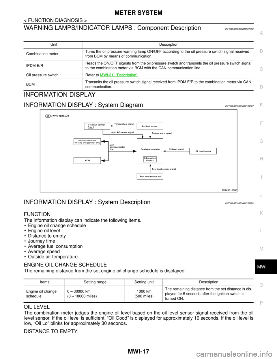
INFORMATION DISPLAY
INFORMATION DISPLAY : System DiagramINFOID:0000000001374677
INFORMATION DISPLAY : System DescriptionINFOID:0000000001374678
FUNCTION
The information display can indicate the following items.
Engine oil change schedule
Engine oil level
Distance to empty
Journey time
Average fuel consumption
Average speed
Outside air temperature
ENGINE OIL CHANGE SCHEDULE
The remaining distance from the set engine oil change schedule is displayed.
OIL LEVEL
The combination meter judges the engine oil level based on the oil level sensor signal received from the oil
level sensor. If the oil level is sufficient, “Oil Good” is displayed for approximately 10 seconds. If the oil level is
low, “Oil Lo” blinks for approximately 30 seconds.
DISTANCE TO EMPTY
Unit Description
Combination meterTurns the oil pressure warning lamp ON/OFF according to the oil pressure switch signal received
from BCM by means of communication.
IPDM E/RReads the ON/OFF signals from the oil pressure switch and transmits the oil pressure switch signal
to the combination meter via BCM with the CAN communication line.
Oil pressure switch Refer to MWI-31, "
Description".
BCMTransmits the oil pressure switch signal received from IPDM E/R to the combination meter via CAN
communication.
AWNIA0163GB
Items Setting range Setting unit Description
Engine oil change
schedule0 – 30000 km
(0 – 18000 miles)1000 km
(500 miles)The remaining distance from the set distance is dis-
played for 5 seconds after the ignition switch is
turned ON.
Page 4325 of 5883

MWI-18
< FUNCTION DIAGNOSIS >
METER SYSTEM
The distance to empty indication provides the driver with an estimation of the distance that can be driven
before refueling. The distance to empty is calculated using signals from the fuel level sensor unit (fuel remain-
ing), ECM (fuel consumption) and vehicle speed signals from the ABS actuator and electric unit (control unit).
JOURNY TIME
The travel time since last reset is displayed.
AVERAGE FUEL CONSUMTION
Average fuel consumption indication is calculated using vehicle speed signals from the ABS actuator and elec-
tric unit (control unit) and fuel consumption information from the ECM.
AVERAGE SPEED
The average speed mode can be selected to display the average speed since last reset. The indications are
calculated using vehicle speed signals from the ABS actuator and electric unit (control unit).
OUTSIDE AIR TEMPERATURE
The combination meter indicates the outside air temperature calculated by the temperature signal received
from the ambient sensor.
The indicated temperature is not readily affected by engine heat. It changes only when one of the following
conditions is present.
The temperature detected by the ambient sensor is lower than the indicated temperature
The vehicle speed is greater than 20 km/h (13 MPH)
(This is to prevent the indicated temperature from being affected by engine heat during low-speed driving.)
The ignition switch has been turned to the OFF position for more than 3.5 hours. (The engine is cold.)
When the ambient air temperature falls below 3°C (37°F), the display starts flashing. Approximately 20 sec-
onds later, only “°C” flashes.
NOTE:
On vehicles equipped with auto A/C, the ambient sensor signal is shared with the front air control. The combi-
nation meter is notified of the signal sharing via the auto A/C sense circuit.
Page 4326 of 5883
MWI
METER SYSTEM
MWI-19
< FUNCTION DIAGNOSIS >
C
D
E
F
G
H
I
J
K
L
MB A
O
P
INFORMATION DISPLAY : Component Parts LocationINFOID:0000000001537312
INFORMATION DISPLAY : Component DescriptionINFOID:0000000001537301
1. Combination meter M24 2. ABS actuator and electric unit (control
unit) E33 (RHD models) (MR18DE
shown, HR16DE and K9K similar)3. IPDM E/R E43, E46, E48 (MR18DE
shown, HR16DE and K9K similar)
4. ECM E16 (MR18DE shown, HR16DE
and K9K similar)5. ABS actuator and electric unit (control
unit) E33 (LHD models)6. Fuel level sensor unit and fuel pump
B40 (view with rear seat and inspection
hole cover removed)
⇐: Front
7. Oil pressure switch F32 (HR16DE and
MR18DE models) (view with engine re-
moved)8. Oil level sensor F60 (HR16DE and
MR18DE models) (view with engine re-
moved)9. Oil pressure switch F32 (K9K models)
(view with engine removed)
10. Oil level sensor F60 (K9K models)
(view with engine removed)
ALNIA0624ZZ
Page 4327 of 5883
MWI-20
< FUNCTION DIAGNOSIS >
METER SYSTEM
Unit Description
Combination meter Controls the information display according to the signal received from each unit.
Fuel level sensor unit Refer to MWI-29, "
Description".
ECMTransmits the following signals to the combination meter via CAN communication line.
Engine speed signal Fuel consumption monitor signal
ABS actuator and electric unit
(control unit)Transmits the vehicle speed signal to the combination meter via CAN communication line.
Ambient sensor Refer to MWI-34, "
Description".
Oil level sensor Refer to MWI-32, "
Description".
Page 4336 of 5883

MWI
FUEL LEVEL SENSOR SIGNAL CIRCUIT
MWI-29
< COMPONENT DIAGNOSIS >
C
D
E
F
G
H
I
J
K
L
MB A
O
P
FUEL LEVEL SENSOR SIGNAL CIRCUIT
DescriptionINFOID:0000000001374693
The fuel level sensor unit and fuel pump detects the approximate fuel level in the fuel tank and transmits the
fuel level signal to the combination meter.
Component Function CheckINFOID:0000000001374694
1.COMBINATION METER INPUT SIGNAL
1. Select “METER/M&A” on CONSULT-III.
2. Using “FUEL METER” of “DATA MONITOR”, compare the value of DATA MONITOR with fuel gauge
pointer of combination meter.
Does the data monitor value approximately match the fuel gauge indication?
YES >> Inspection End.
NO >> Replace combination meter. Refer to MWI-94, "
Removal and Installation".
Diagnosis ProcedureINFOID:0000000001374695
1.CHECK HARNESS CONNECTOR
1. Turn ignition switch OFF.
2. Check combination meter and fuel level sensor unit terminals (meter-side and harness-side) for poor con-
nection.
Is the inspection result normal?
YES >> GO TO 2
NO >> Repair or replace terminals or connectors.
2.CHECK FUEL LEVEL SENSOR UNIT CIRCUIT
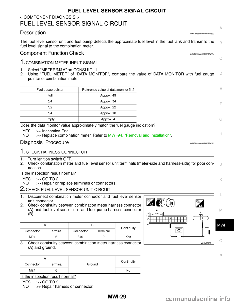
1. Disconnect combination meter connector and fuel level sensor
unit connector.
2. Check continuity between combination meter harness connector
(A) and fuel level sensor unit and fuel pump harness connector
(B).
3. Check continuity between combination meter harness connector
(A) and ground.
Is the inspection result normal?
YES >> GO TO 3
NO >> Repair harness or connector.
Fuel gauge pointer Reference value of data monitor [lit.]
Full Approx. 49
3/4 Approx. 34
1/2 Approx. 22
1/4 Approx. 10
Empty Approx. 4
AB
Continuity
Connector Terminal Connector Terminal
M24 6 B40 2 Yes
A
GroundContinuity
Connector Terminal
M24 6 No
WKIA6018E
Page 4337 of 5883

MWI-30
< COMPONENT DIAGNOSIS >
FUEL LEVEL SENSOR SIGNAL CIRCUIT
3.CHECK FUEL LEVEL SENSOR UNIT GROUND CIRCUIT
1. Check continuity between combination meter harness connector
(A) and fuel level sensor unit and fuel pump harness connector
(B).
2. Check continuity between combination meter harness connector
(A) and ground.
Is the inspection result normal?
YES >> GO TO 4
NO >> Repair harness or connector.
4.CHECK INSTALLATION CONDITION
Check fuel level sensor unit installation, and check whether the float arm interferes or binds with any of the
internal components in the fuel tank.
Is the inspection result normal?
YES >> Inspection End.
NO >> Install the fuel level sensor unit properly.
Component InspectionINFOID:0000000001374696
1.REMOVE FUEL LEVEL SENSOR UNIT
Remove the fuel level sensor unit. Refer to FL-8, "
Removal and Installation".
>> GO TO 2
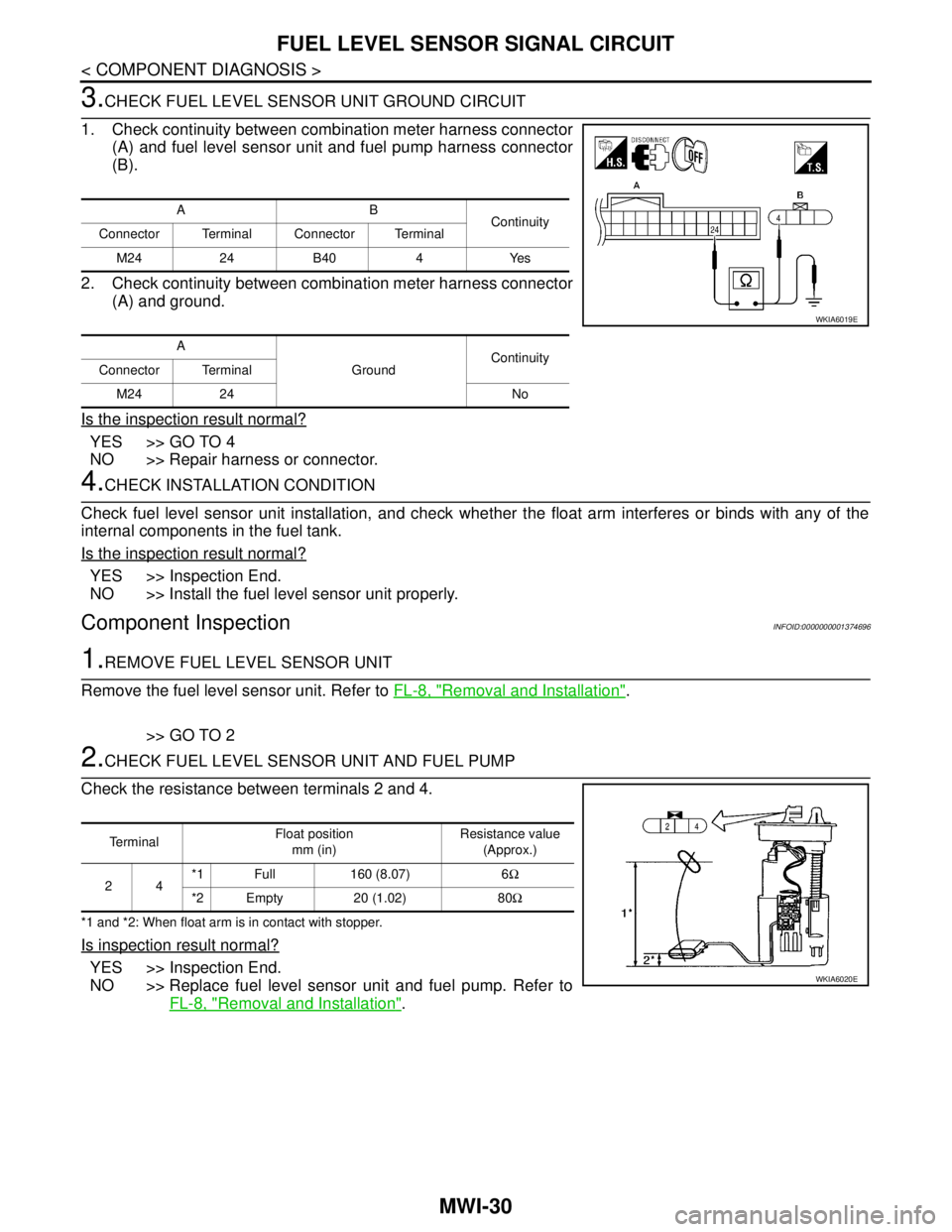
2.CHECK FUEL LEVEL SENSOR UNIT AND FUEL PUMP
Check the resistance between terminals 2 and 4.
*1 and *2: When float arm is in contact with stopper.
Is inspection result normal?
YES >> Inspection End.
NO >> Replace fuel level sensor unit and fuel pump. Refer to
FL-8, "
Removal and Installation".
AB
Continuity
Connector Terminal Connector Terminal
M24 24 B40 4 Yes
A
GroundContinuity
Connector Terminal
M24 24 No
WKIA6019E
Te r m i n a lFloat position
mm (in)Resistance value
(Approx.)
24*1 Full 160 (8.07) 6Ω
*2 Empty 20 (1.02) 80Ω
WKIA6020E