Page 1594 of 2896
DTC P0507 ISC SYSTEM
EC-425
C
D
E
F
G
H
I
J
K
L
MA
EC
Revision: June 20062007 Versa
DTC P0507 ISC SYSTEMPFP:23781
DescriptionUBS00QK9
NOTE:
If DTC P0507 is displayed with other DTC, first perform the trouble diagnosis for the other DTC.
The ECM controls the engine idle speed to a specified level through the fine adjustment of the air, which is let
into the intake manifold, by operating the electric throttle control actuator. The operating of the throttle valve is
varied to allow for optimum control of the engine idling speed. The ECM calculates the actual engine speed
from signals of camshaft position sensor (POS) and camshaft position sensor (PHASE).
The ECM controls the electric throttle control actuator so that the engine speed coincides with the target value
memorized in the ECM. The target engine speed is the lowest speed at which the engine can operate steadily.
The optimum value stored in the ECM is determined by taking into consideration various engine conditions,
such as during warming up, deceleration, and engine load (air conditioner, power steering and cooling fan
operation, etc.).
On Board Diagnosis LogicUBS00QKA
DTC Confirmation ProcedureUBS00QKB
NOTE:
�If DTC Confirmation Procedure has been previously conducted, always turn ignition switch OFF and wait
at least 10 seconds before conducting the next test.
�If the target idle speed is out of the specified value, perform EC-78, "Idle Air Volume Learning" ,
before conducting DTC Confirmation Procedure. For the target idle speed, refer to the EC-594,
"SERVICE DATA AND SPECIFICATIONS (SDS)" .
TESTING CONDITION:
�Before performing the following procedure, confirm that battery voltage is more than 11V at idle.
�Always perform the test at a temperature above −10°C (14°F).
WITH CONSULT-II
1. Open engine hood.
2. Start engine and warm it up to normal operating temperature.
3. Turn ignition switch OFF and wait at least 10 seconds.
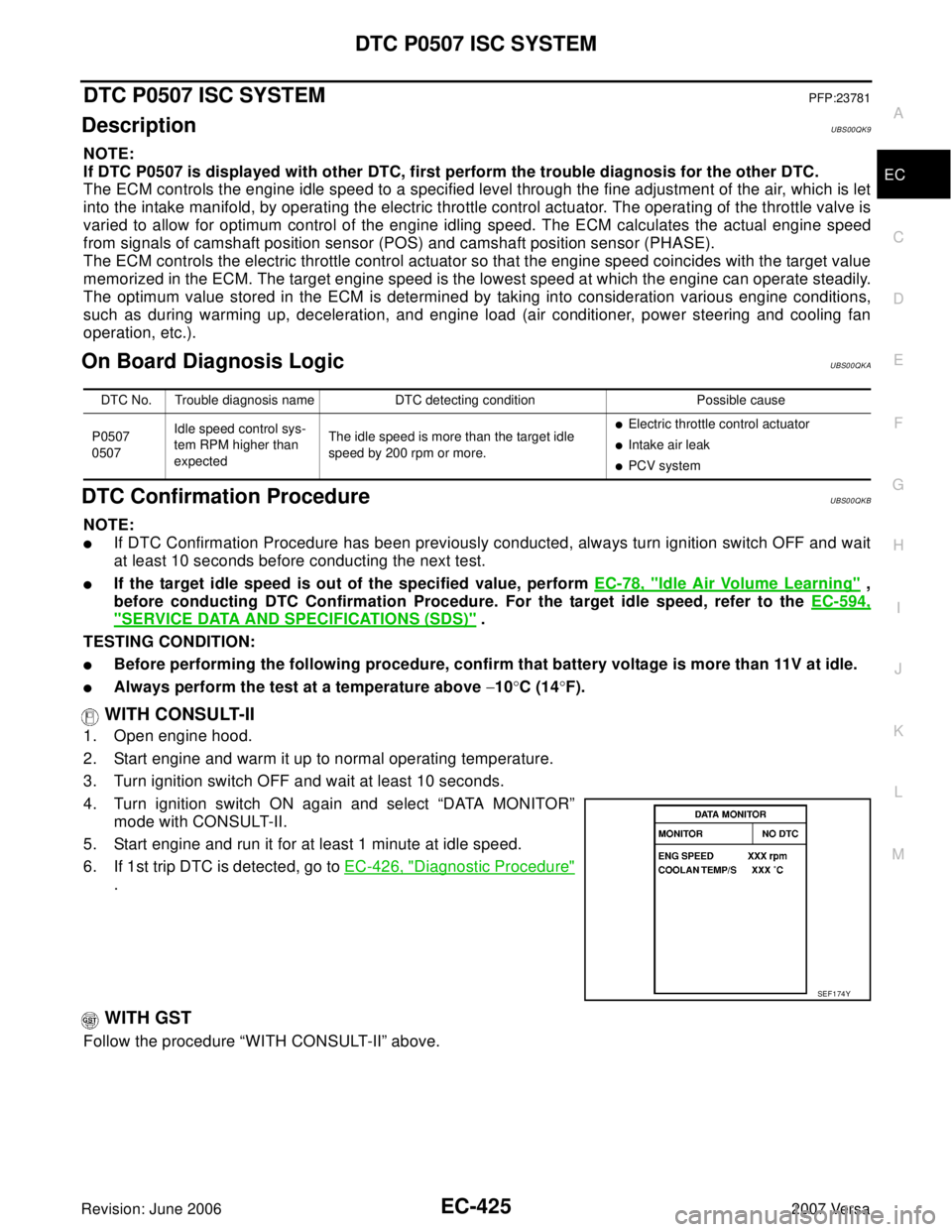
4. Turn ignition switch ON again and select “DATA MONITOR”
mode with CONSULT-II.
5. Start engine and run it for at least 1 minute at idle speed.
6. If 1st trip DTC is detected, go to EC-426, "
Diagnostic Procedure"
.
WITH GST
Follow the procedure “WITH CONSULT-II” above.
DTC No. Trouble diagnosis name DTC detecting condition Possible cause
P0507
0507Idle speed control sys-
tem RPM higher than
expectedThe idle speed is more than the target idle
speed by 200 rpm or more.
�Electric throttle control actuator
�Intake air leak
�PCV system
SEF 1 74 Y
Page 1635 of 2896
EC-466Revision: June 2006
DTC P1564 ASCD STEERING SWITCH
2007 Versa
DTC P1564 ASCD STEERING SWITCHPFP:25551
Component DescriptionUBS00QLF
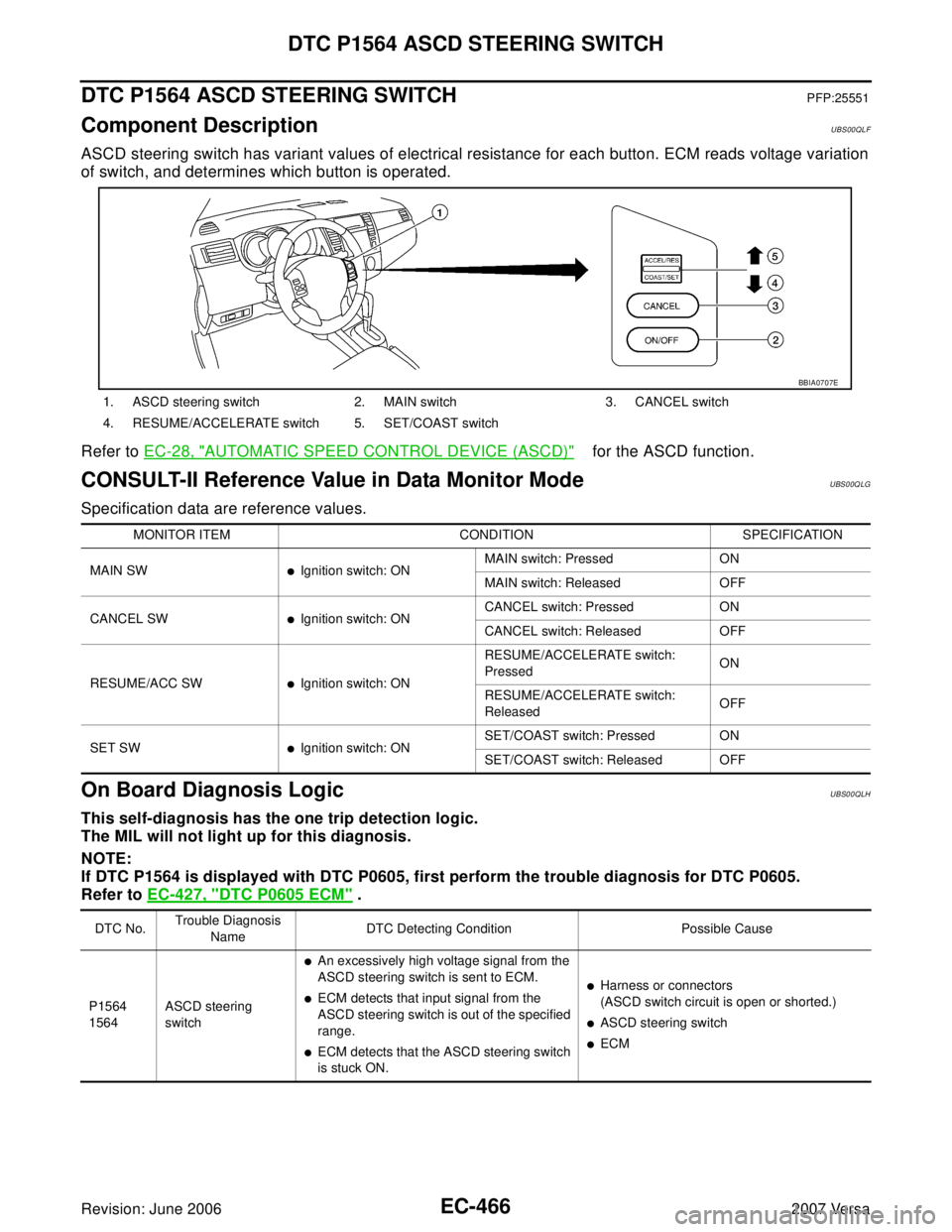
ASCD steering switch has variant values of electrical resistance for each button. ECM reads voltage variation
of switch, and determines which button is operated.
Refer to EC-28, "
AUTOMATIC SPEED CONTROL DEVICE (ASCD)" for the ASCD function.
CONSULT-II Reference Value in Data Monitor ModeUBS00Q LG
Specification data are reference values.
On Board Diagnosis LogicUBS00QLH
This self-diagnosis has the one trip detection logic.
The MIL will not light up for this diagnosis.
NOTE:
If DTC P1564 is displayed with DTC P0605, first perform the trouble diagnosis for DTC P0605.
Refer to EC-427, "
DTC P0605 ECM" .
1. ASCD steering switch 2. MAIN switch 3. CANCEL switch
4. RESUME/ACCELERATE switch 5. SET/COAST switch
BBIA0707E
MONITOR ITEM CONDITION SPECIFICATION
MAIN SW
�Ignition switch: ONMAIN switch: Pressed ON
MAIN switch: Released OFF
CANCEL SW
�Ignition switch: ONCANCEL switch: Pressed ON
CANCEL switch: Released OFF
RESUME/ACC SW
�Ignition switch: ONRESUME/ACCELERATE switch:
PressedON
RESUME/ACCELERATE switch:
ReleasedOFF
SET SW
�Ignition switch: ONSET/COAST switch: Pressed ON
SET/COAST switch: Released OFF
DTC No.Trouble Diagnosis
NameDTC Detecting Condition Possible Cause
P1564
1564ASCD steering
switch
�An excessively high voltage signal from the
ASCD steering switch is sent to ECM.
�ECM detects that input signal from the
ASCD steering switch is out of the specified
range.
�ECM detects that the ASCD steering switch
is stuck ON.
�Harness or connectors
(ASCD switch circuit is open or shorted.)
�ASCD steering switch
�ECM
Page 1636 of 2896
DTC P1564 ASCD STEERING SWITCH
EC-467
C
D
E
F
G
H
I
J
K
L
MA
EC
Revision: June 20062007 Versa
DTC Confirmation ProcedureUBS00QLI
NOTE:
If DTC Confirmation Procedure has been previously conducted, always turn ignition switch OFF and wait at
least 10 seconds before conducting the next test.
WITH CONSULT-II
1. Turn ignition switch ON.
2. Select “DATA MONITOR” mode with CONSULT-II.
3. Wait at least 10 seconds.
4. Press MAIN switch for at least 10 seconds, then release it and
wait at least 10 seconds.
5. Press CANCEL switch for at least 10 seconds, then release it
and wait at least 10 seconds.
6. Press RESUME/ACCELERATE switch for at least 10 seconds,
then release it and wait at least 10 seconds.
7. Press SET/COAST switch for at least 10 seconds, then release
it and wait at least 10 seconds.
8. If DTC is detected, go to EC-469, "
Diagnostic Procedure" .
WITH GST
Follow the procedure “WITH CONSULT-II” above.
SEF 0 58 Y
Page 1637 of 2896
EC-468Revision: June 2006
DTC P1564 ASCD STEERING SWITCH
2007 Versa
Wiring DiagramUBS00QLJ
BBWA2663E
Page 1638 of 2896
DTC P1564 ASCD STEERING SWITCH
EC-469
C
D
E
F
G
H
I
J
K
L
MA
EC
Revision: June 20062007 Versa
Specification data are reference values and are measured between each terminal and ground.
CAUTION:
Do not use ECM ground terminals when measuring input/output voltage. Doing so may result in dam-
age to the ECM's transistor. Use a ground other than ECM terminals, such as the ground.
Diagnostic ProcedureUBS00QLK
1. CHECK GROUND CONNECTIONS
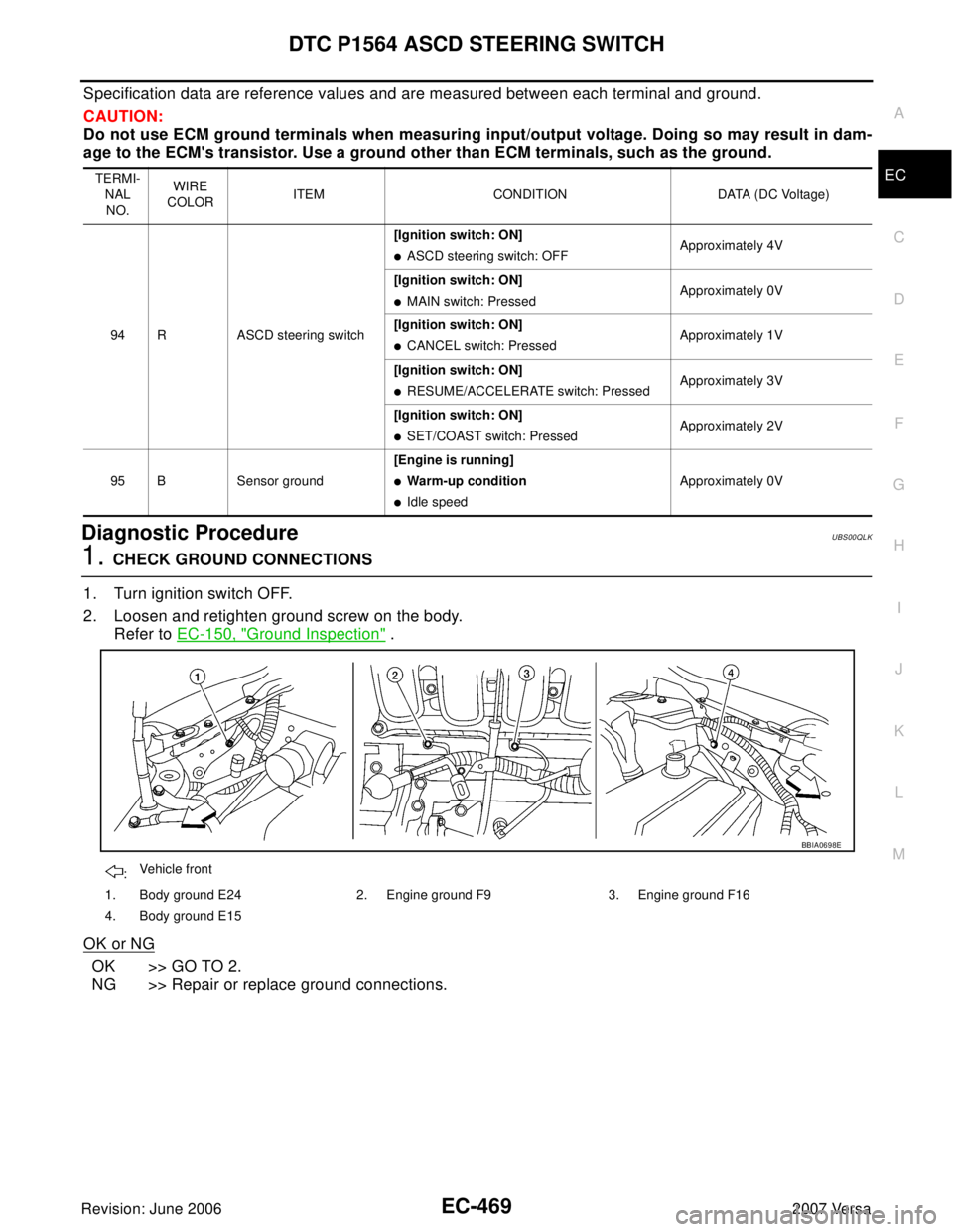
1. Turn ignition switch OFF.
2. Loosen and retighten ground screw on the body.
Refer to EC-150, "
Ground Inspection" .
OK or NG
OK >> GO TO 2.
NG >> Repair or replace ground connections.
TERMI-
NAL
NO.WIRE
COLORITEM CONDITION DATA (DC Voltage)
94 R ASCD steering switch[Ignition switch: ON]
�ASCD steering switch: OFFApproximately 4V
[Ignition switch: ON]
�MAIN switch: PressedApproximately 0V
[Ignition switch: ON]
�CANCEL switch: PressedApproximately 1V
[Ignition switch: ON]
�RESUME/ACCELERATE switch: PressedApproximately 3V
[Ignition switch: ON]
�SET/COAST switch: PressedApproximately 2V
95 B Sensor ground[Engine is running]
�Warm-up condition
�Idle speedApproximately 0V
:Vehicle front
1. Body ground E24 2. Engine ground F9 3. Engine ground F16
4. Body ground E15
BBIA0698E
Page 1639 of 2896
EC-470Revision: June 2006
DTC P1564 ASCD STEERING SWITCH
2007 Versa
2. CHECK ASCD STEERING SWITCH CIRCUIT
With CONSULT-II
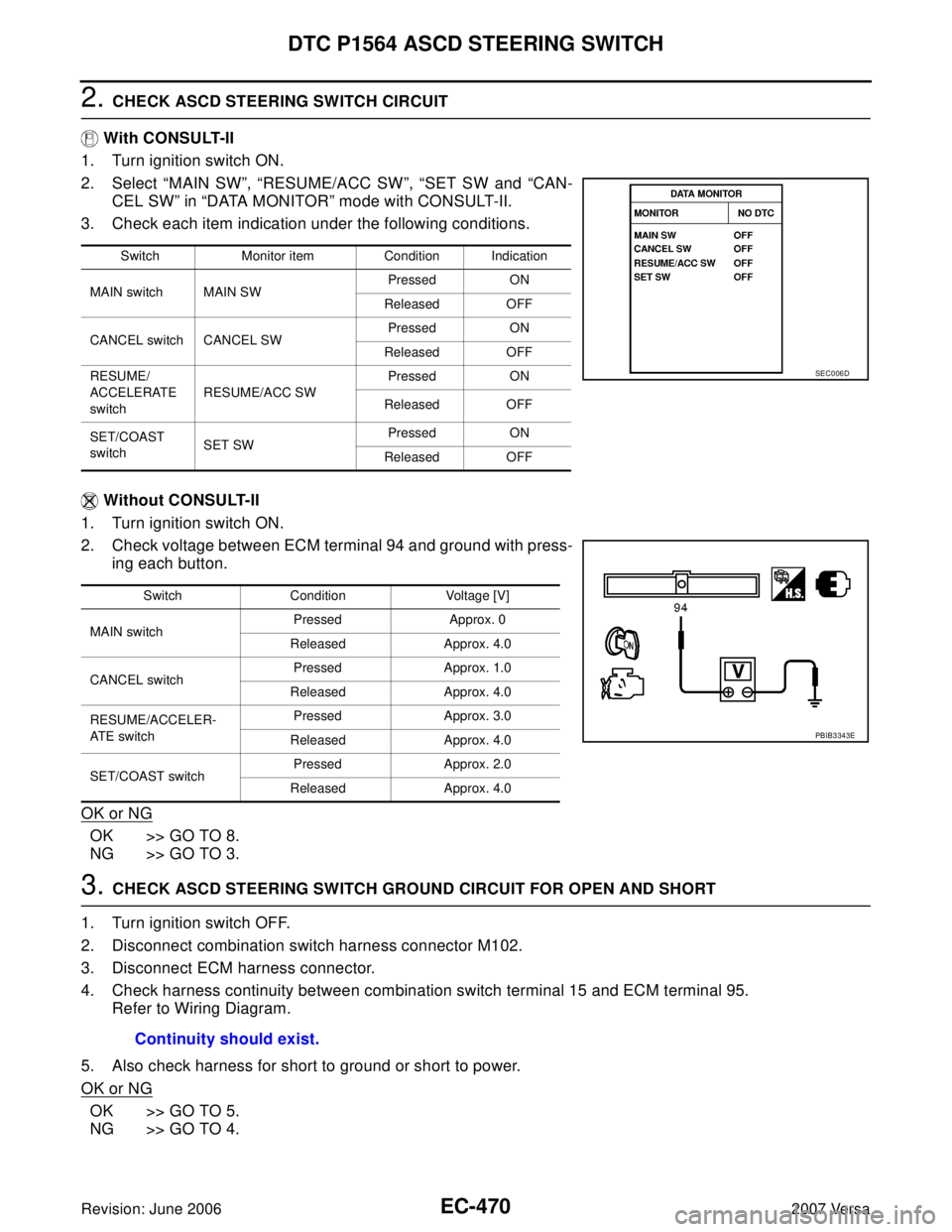
1. Turn ignition switch ON.
2. Select “MAIN SW”, “RESUME/ACC SW”, “SET SW and “CAN-
CEL SW” in “DATA MONITOR” mode with CONSULT-II.
3. Check each item indication under the following conditions.
Without CONSULT-II
1. Turn ignition switch ON.
2. Check voltage between ECM terminal 94 and ground with press-
ing each button.
OK or NG
OK >> GO TO 8.
NG >> GO TO 3.
3. CHECK ASCD STEERING SWITCH GROUND CIRCUIT FOR OPEN AND SHORT
1. Turn ignition switch OFF.
2. Disconnect combination switch harness connector M102.
3. Disconnect ECM harness connector.
4. Check harness continuity between combination switch terminal 15 and ECM terminal 95.
Refer to Wiring Diagram.
5. Also check harness for short to ground or short to power.
OK or NG
OK >> GO TO 5.
NG >> GO TO 4.
Switch Monitor item Condition Indication
MAIN switch MAIN SWPressed ON
Released OFF
CANCEL switch CANCEL SWPressed ON
Released OFF
RESUME/
ACCELERATE
switchRESUME/ACC SWPressed ON
Released OFF
SET/COAST
switchSET SWPressed ON
Released OFF
SEC0 06 D
Switch Condition Voltage [V]
MAIN switchPressed Approx. 0
Released Approx. 4.0
CANCEL switchPressed Approx. 1.0
Released Approx. 4.0
RESUME/ACCELER-
AT E s w it c hPressed Approx. 3.0
Released Approx. 4.0
SET/COAST switchPressed Approx. 2.0
Released Approx. 4.0
PBIB3343E
Continuity should exist.
Page 1640 of 2896
DTC P1564 ASCD STEERING SWITCH
EC-471
C
D
E
F
G
H
I
J
K
L
MA
EC
Revision: June 20062007 Versa
4. DETECT MALFUNCTIONING PART
Check the following.
�Harness connectors M69, E7
�Combination switch (spiral cable)
�Harness for open and short between ECM and combination switch
>> Repair open circuit or short to ground or short to power in harness or connectors.
5. CHECK ASCD STEERING SWITCH INPUT SIGNAL CIRCUIT FOR OPEN AND SHORT
1. Check harness continuity between ECM terminal 94 and combination switch terminal 14.
Refer to Wiring Diagram.
2. Also check harness for short to ground and short to power.
OK or NG
OK >> GO TO 7.
NG >> GO TO 6.
6. DETECT MALFUNCTIONING PART
Check the following.
�Harness connectors M69, E7
�Combination switch (spiral cable)
�Harness for open and short between ECM and combination switch
>> Repair open circuit or short to ground or short to power in harness or connectors.
7. CHECK ASCD STEERING SWITCH
Refer to EC-472, "
Component Inspection" .
OK or NG
OK >> GO TO 7.
NG >> Replace ASCD steering switch.
8. CHECK INTERMITTENT INCIDENT
Refer to EC-143, "
TROUBLE DIAGNOSIS FOR INTERMITTENT INCIDENT" .
>>INSPECTION END Continuity should exist.
Page 1641 of 2896
EC-472Revision: June 2006
DTC P1564 ASCD STEERING SWITCH
2007 Versa
Component InspectionUBS00QLL
ASCD STEERING SWITCH
1. Disconnect combination switch (spiral cable) harness connector M102.
2. Check continuity between combination switch (spiral cable) ter-
minals 14 and 15 with pushing each switch.
If NG, replace ASCD steering switch.
Switch Condition Resistance [Ω]
MAIN switchPressed Approx. 0
Released Approx. 4,000
CANCEL switchPressed Approx. 250
Released Approx. 4,000
RESUME/ACCELERATE
switchPressed Approx. 1,480
Released Approx. 4,000
SET/COAST switchPressed Approx. 660
Released Approx. 4,000
PBIB2549E