Page 2111 of 2896

INSTRUMENT PANEL ASSEMBLY
IP-11
C
D
E
F
G
H
J
K
L
MA
B
IP
Revision: June 20062007 Versa
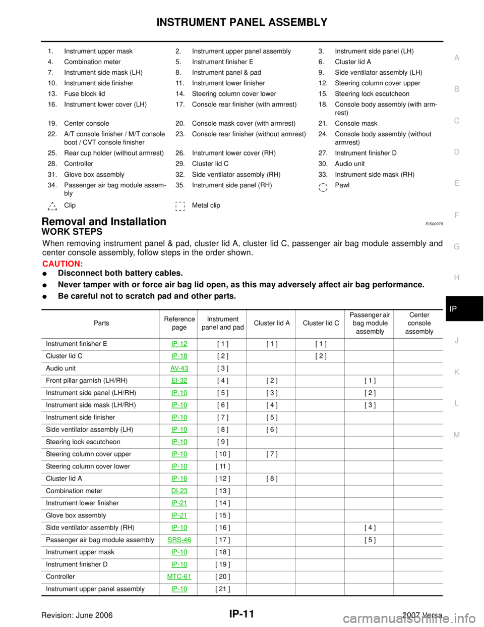
Removal and InstallationEIS00979
WORK STEPS
When removing instrument panel & pad, cluster lid A, cluster lid C, passenger air bag module assembly and
center console assembly, follow steps in the order shown.
CAUTION:
�Disconnect both battery cables.
�Never tamper with or force air bag lid open, as this may adversely affect air bag performance.
�Be careful not to scratch pad and other parts.
1. Instrument upper mask 2. Instrument upper panel assembly 3. Instrument side panel (LH)
4. Combination meter 5. Instrument finisher E 6. Cluster lid A
7. Instrument side mask (LH) 8. Instrument panel & pad 9. Side ventilator assembly (LH)
10. Instrument side finisher 11. Instrument lower finisher 12. Steering column cover upper
13. Fuse block lid 14. Steering column cover lower 15. Steering lock escutcheon
16. Instrument lower cover (LH) 17. Console rear finisher (with armrest) 18. Console body assembly (with arm-
rest)
19. Center console 20. Console mask cover (with armrest) 21. Console mask
22. A/T console finisher / M/T console
boot / CVT console finisher23. Console rear finisher (without armrest) 24. Console body assembly (without
armrest)
25. Rear cup holder (without armrest) 26. Instrument lower cover (RH) 27. Instrument finisher D
28. Controller 29. Cluster lid C 30. Audio unit
31. Glove box assembly 32. Side ventilator assembly (RH) 33. Instrument side mask (RH)
34. Passenger air bag module assem-
bly35. Instrument side panel (RH) Pawl
Clip Metal clip
PartsReference
pageInstrument
panel and padCluster lid A Cluster lid C Passenger air
bag module
assemblyCenter
console
assembly
Instrument finisher EIP-12
[ 1 ] [ 1 ] [ 1 ]
Cluster lid CIP-18
[ 2 ] [ 2 ]
Audio unitAV-4 3
[ 3 ]
Front pillar garnish (LH/RH)EI-32
[ 4 ] [ 2 ] [ 1 ]
Instrument side panel (LH/RH)IP-10
[ 5 ] [ 3 ] [ 2 ]
Instrument side mask (LH/RH)IP-10
[ 6 ] [ 4 ] [ 3 ]
Instrument side finisherIP-10
[ 7 ] [ 5 ]
Side ventilator assembly (LH)IP-10
[ 8 ] [ 6 ]
Steering lock escutcheonIP-10
[ 9 ]
Steering column cover upperIP-10
[ 10 ] [ 7 ]
Steering column cover lowerIP-10
[ 11 ]
Cluster lid AIP-16
[ 12 ] [ 8 ]
Combination meterDI-23
[ 13 ]
Instrument lower finisherIP-21
[ 14 ]
Glove box assemblyIP-21
[ 15 ]
Side ventilator assembly (RH)IP-10
[ 16 ] [ 4 ]
Passenger air bag module assemblySRS-46
[ 17 ] [ 5 ]
Instrument upper maskIP-10
[ 18 ]
Instrument finisher DIP-10
[ 19 ]
Controller MTC-61
[ 20 ]
Instrument upper panel assembly IP-10
[ 21 ]
Page 2114 of 2896

IP-14
INSTRUMENT PANEL ASSEMBLY
Revision: June 20062007 Versa
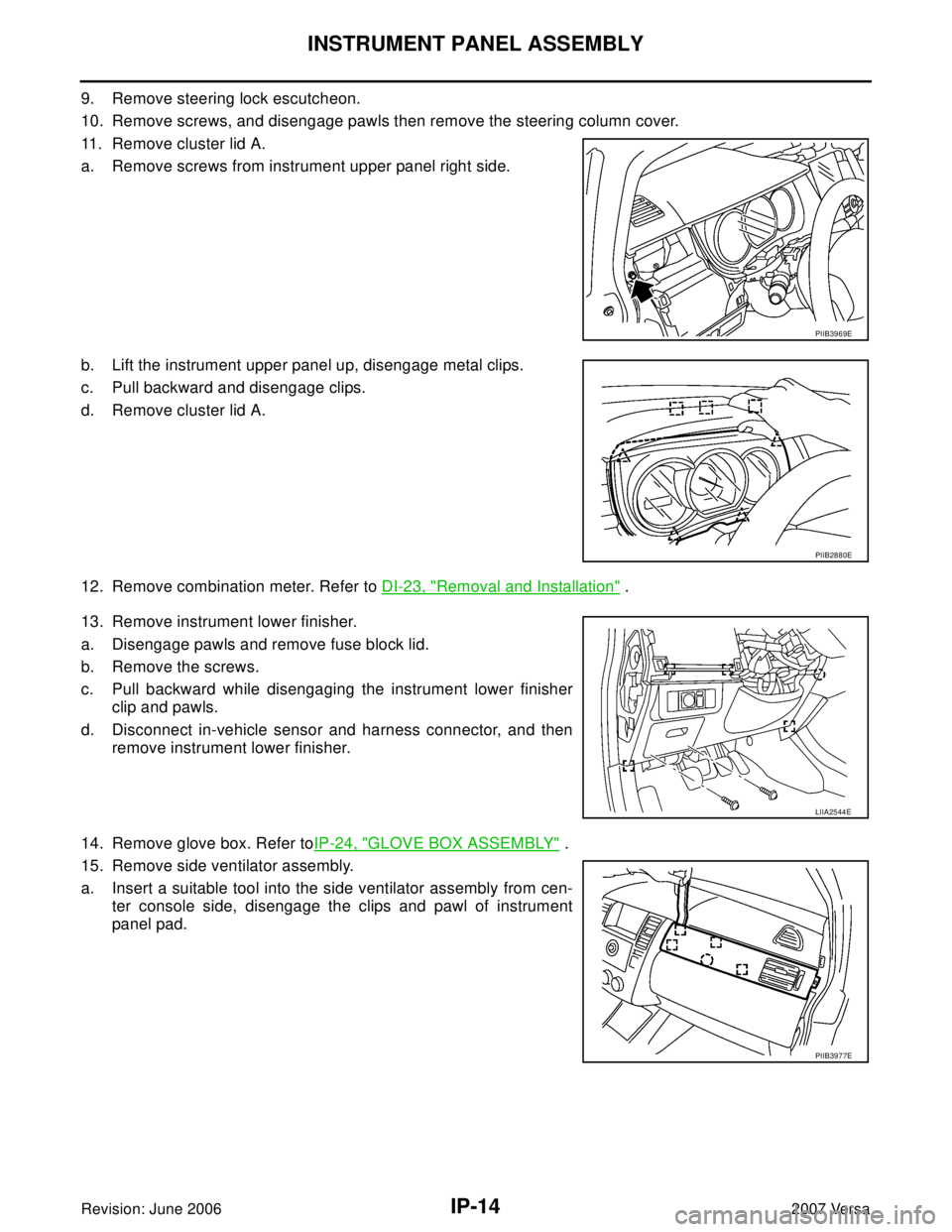
9. Remove steering lock escutcheon.
10. Remove screws, and disengage pawls then remove the steering column cover.
11. Remove cluster lid A.
a. Remove screws from instrument upper panel right side.
b. Lift the instrument upper panel up, disengage metal clips.
c. Pull backward and disengage clips.
d. Remove cluster lid A.
12. Remove combination meter. Refer to DI-23, "
Removal and Installation" .
13. Remove instrument lower finisher.
a. Disengage pawls and remove fuse block lid.
b. Remove the screws.
c. Pull backward while disengaging the instrument lower finisher
clip and pawls.
d. Disconnect in-vehicle sensor and harness connector, and then
remove instrument lower finisher.
14. Remove glove box. Refer toIP-24, "
GLOVE BOX ASSEMBLY" .
15. Remove side ventilator assembly.
a. Insert a suitable tool into the side ventilator assembly from cen-
ter console side, disengage the clips and pawl of instrument
panel pad.
PIIB3969E
PIIB2880E
LIIA2544E
PIIB3977E
Page 2117 of 2896
INSTRUMENT PANEL ASSEMBLY
IP-17
C
D
E
F
G
H
J
K
L
MA
B
IP
Revision: June 20062007 Versa
5. Insert a remover into upper space of instrument mask.
6. Disengage pawls, and then remove instrument side mask.
7. Insert a remover into space of instrument side finisher.
8. Disengage metal clips, and then remove instrument side fin-
isher.
9. Insert suitable tool into the bottom gap of side ventilator assem-
bly after removing the instrument side mask, push against A and
B as shown to disengage the pawls.
10. Lift the side ventilator up from the bottom, pull backward while
disengaging the side ventilator assembly's upper pawls, and
then remove the side ventilator.
11. Remove screws, and disengage pawls.
12. Remove steering column cover upper.
PIIB2448E
PIIB2440E
WIIA1226E
PIIB3976E
Page 2120 of 2896
IP-20
INSTRUMENT PANEL ASSEMBLY
Revision: June 20062007 Versa
9. Insert suitable tool into the bottom gap of side ventilator assem-
bly after removing the instrument side mask, push against A and
B as shown to disengage the pawls.
10. Lift the side ventilator up from the bottom, pull backward while
disengaging the side ventilator assembly's upper pawls, and
then remove the side ventilator.
11. Remove screws, and disengage pawls.
12. Remove steering column cover upper.
13. Remove screws from instrument upper panel right side.
14. Lift the instrument upper panel up, disengage metal clips.
15. Pull backward and disengage clips.
16. Remove cluster lid A.
WIIA1226E
PIIB3976E
PIIB3969E
PIIB2880E
Page 2136 of 2896
LAN-10
[CAN FUNDAMENTAL]
TROUBLE DIAGNOSIS
Revision: June 20062007 Versa
Example: Main Line Between Data Link Connector and ABS Actuator and Electric Unit (Con-
trol Unit) Open Circuit
SKIB8740E
Unit name Symptom
ECM Engine torque limiting is affected, and shift harshness increases.
BCM
�Reverse warning chime does not sound.
�The front wiper moves under continuous operation mode even though the front
wiper switch being in the intermittent position.
EPS control unit The steering effort increases.
Combination meter
�The shift position indicator and OD OFF indicator turn OFF.
�The speedometer is inoperative.
�The odo/trip meter stops.
ABS actuator and electric unit (control unit) Normal operation.
TCM No impact on operation.
IPDM E/RWhen the ignition switch is ON,
�The headlamps (Lo) turn ON.
�The cooling fan continues to rotate.
Page 2137 of 2896
![NISSAN LATIO 2007 Service Repair Manual TROUBLE DIAGNOSIS
LAN-11
[CAN FUNDAMENTAL]
C
D
E
F
G
H
I
J
L
MA
B
LAN
Revision: June 20062007 Versa
Example: CAN-H, CAN-L Harness Short Circuit
SKIB8741E
Unit name Symptom
ECM
�Engine torque limiting NISSAN LATIO 2007 Service Repair Manual TROUBLE DIAGNOSIS
LAN-11
[CAN FUNDAMENTAL]
C
D
E
F
G
H
I
J
L
MA
B
LAN
Revision: June 20062007 Versa
Example: CAN-H, CAN-L Harness Short Circuit
SKIB8741E
Unit name Symptom
ECM
�Engine torque limiting](/manual-img/5/57361/w960_57361-2136.png)
TROUBLE DIAGNOSIS
LAN-11
[CAN FUNDAMENTAL]
C
D
E
F
G
H
I
J
L
MA
B
LAN
Revision: June 20062007 Versa
Example: CAN-H, CAN-L Harness Short Circuit
SKIB8741E
Unit name Symptom
ECM
�Engine torque limiting is affected, and shift harshness increases.
�Engine speed drops.
BCM
�Reverse warning chime does not sound.
�The front wiper moves under continuous operation mode even though the front
wiper switch being in the intermittent position.
�The room lamp does not turn ON.
�The engine does not start (if an error or malfunction occurs while turning the igni-
tion switch is OFF.)
�The steering lock does not release (if an error or malfunction occurs while turning
the ignition switch is OFF.)
EPS control unit The steering effort increases.
Combination meter
�The tachometer and the speedometer do not move.
�Warning lamps turn ON.
�Indicator lamps do not turn ON.
ABS actuator and electric unit (control unit) Normal operation.
TCM No impact on operation.
IPDM E/RWhen the ignition switch is ON,
�The headlamps (Lo) turn ON.
�The cooling fan continues to rotate.
Page 2273 of 2896
LIGHTING AND TURN SIGNAL SWITCH
LT-65
C
D
E
F
G
H
I
J
L
MA
B
LT
Revision: June 20062007 Versa
LIGHTING AND TURN SIGNAL SWITCHPFP:25540
Removal and InstallationEKS00HYH
REMOVAL
1. Remove steering column cover. Refer to IP-10, "INSTRUMENT PANEL ASSEMBLY" .
2. While pressing pawls (A) in direction as shown, pull lighting and
turn signal switch (1) toward LH door and disconnect from the
base.
INSTALLATION
Installation is in the reverse order of removal.
PKIC1018E
Page 2339 of 2896

GENERAL MAINTENANCE
MA-5
C
D
E
F
G
H
I
J
K
MA
B
MA
Revision: June 20062007 Versa
GENERAL MAINTENANCEPFP:00000
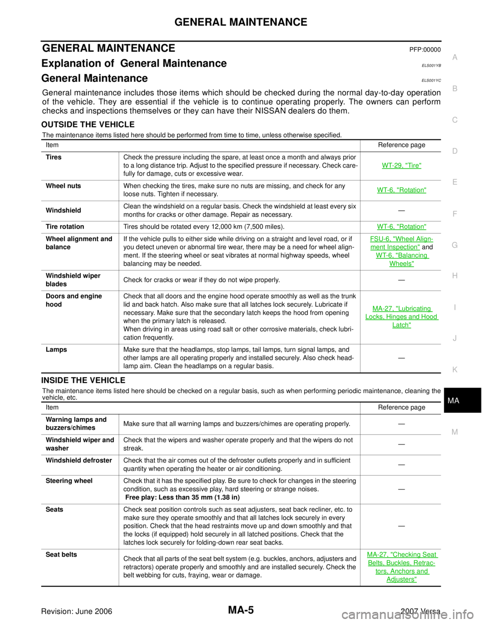
Explanation of General MaintenanceELS001YB
General MaintenanceELS001YC
General maintenance includes those items which should be checked during the normal day-to-day operation
of the vehicle. They are essential if the vehicle is to continue operating properly. The owners can perform
checks and inspections themselves or they can have their NISSAN dealers do them.
OUTSIDE THE VEHICLE
The maintenance items listed here should be performed from time to time, unless otherwise specified.
INSIDE THE VEHICLE
The maintenance items listed here should be checked on a regular basis, such as when performing periodic maintenance, cleaning the
vehicle, etc.ItemReference page
TiresCheck the pressure including the spare, at least once a month and always prior
to a long distance trip. Adjust to the specified pressure if necessary. Check care-
fully for damage, cuts or excessive wear.WT-29, "
Tire"
Wheel nutsWhen checking the tires, make sure no nuts are missing, and check for any
loose nuts. Tighten if necessary.WT-6, "Rotation"
WindshieldClean the windshield on a regular basis. Check the windshield at least every six
months for cracks or other damage. Repair as necessary.—
Tire rotationTires should be rotated every 12,000 km (7,500 miles).WT-6, "
Rotation"
Wheel alignment and
balanceIf the vehicle pulls to either side while driving on a straight and level road, or if
you detect uneven or abnormal tire wear, there may be a need for wheel align-
ment. If the steering wheel or seat vibrates at normal highway speeds, wheel
balancing may be needed.FSU-6, "Wheel Align-
ment Inspection" and
WT-6, "
Balancing
Wheels"
Windshield wiper
bladesCheck for cracks or wear if they do not wipe properly. —
Doors and engine
hoodCheck that all doors and the engine hood operate smoothly as well as the trunk
lid and back hatch. Also make sure that all latches lock securely. Lubricate if
necessary. Make sure that the secondary latch keeps the hood from opening
when the primary latch is released.
When driving in areas using road salt or other corrosive materials, check lubri-
cation frequently.MA-27, "
Lubricating
Locks, Hinges and Hood
Latch"
LampsMake sure that the headlamps, stop lamps, tail lamps, turn signal lamps, and
other lamps are all operating properly and installed securely. Also check head-
lamp aim. Clean the headlamps on a regular basis.—
ItemReference page
Warning lamps and
buzzers/chimesMake sure that all warning lamps and buzzers/chimes are operating properly. —
Windshield wiper and
washerCheck that the wipers and washer operate properly and that the wipers do not
streak.—
Windshield defrosterCheck that the air comes out of the defroster outlets properly and in sufficient
quantity when operating the heater or air conditioning.—
Steering wheelCheck that it has the specified play. Be sure to check for changes in the steering
condition, such as excessive play, hard steering or strange noises.
Free play: Less than 35 mm (1.38 in)—
SeatsCheck seat position controls such as seat adjusters, seat back recliner, etc. to
make sure they operate smoothly and that all latches lock securely in every
position. Check that the head restraints move up and down smoothly and that
the locks (if equipped) hold securely in all latched positions. Check that the
latches lock securely for folding-down rear seat backs.—
Seat belts
Check that all parts of the seat belt system (e.g. buckles, anchors, adjusters and
retractors) operate properly and smoothly and are installed securely. Check the
belt webbing for cuts, fraying, wear or damage.MA-27, "
Checking Seat
Belts, Buckles, Retrac-
tors, Anchors and
Adjusters"