Page 597 of 2896
BL-108
INTELLIGENT KEY SYSTEM
Revision: June 20062007 Versa
*1: With continuously variable transmission (CVT).
*2: With manual transmission (M/T).
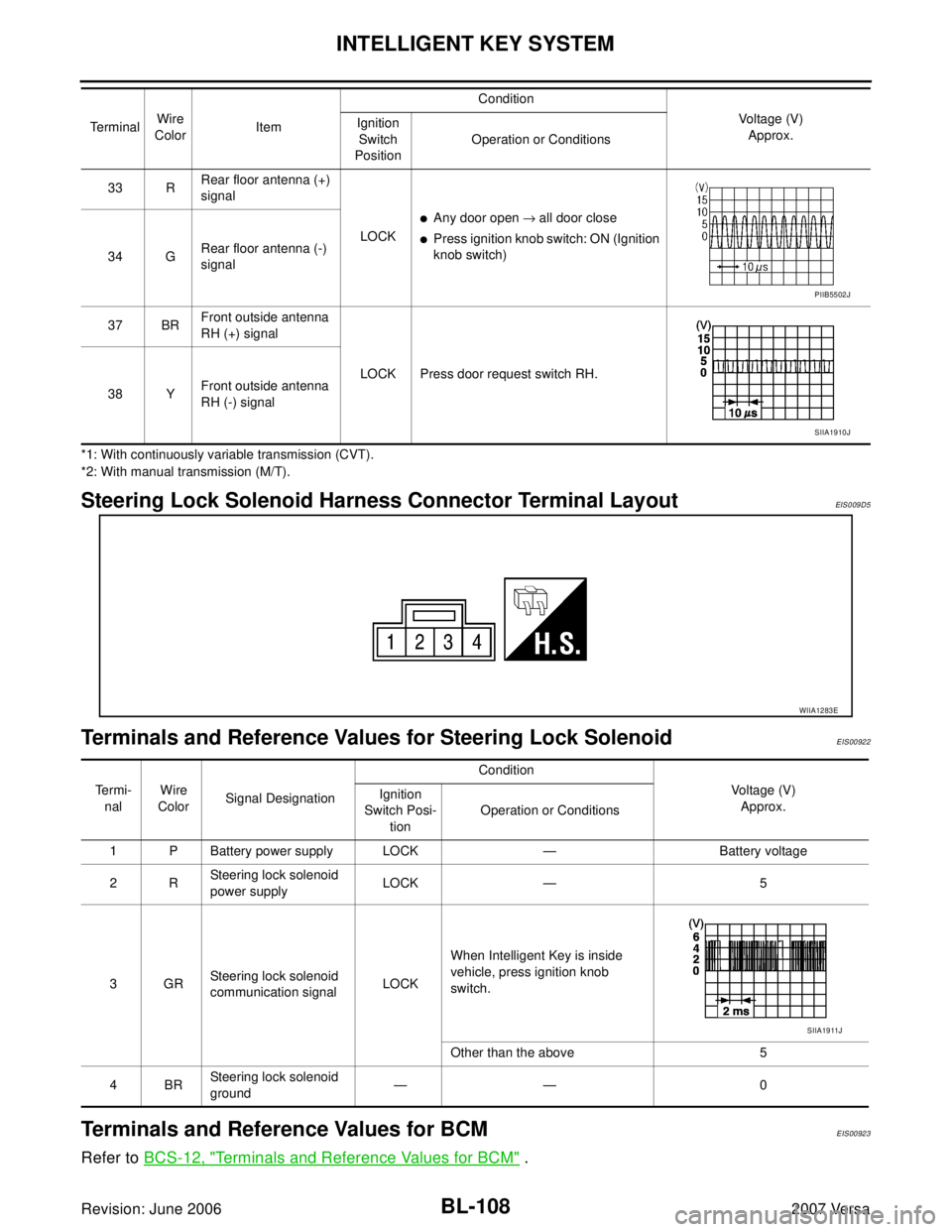
Steering Lock Solenoid Harness Connector Terminal LayoutEIS0 09 D5
Terminals and Reference Values for Steering Lock SolenoidEIS00922
Terminals and Reference Values for BCMEIS00923
Refer to BCS-12, "Terminals and Reference Values for BCM" .
33 RRear floor antenna (+)
signal
LOCK
�Any door open → all door close
�Press ignition knob switch: ON (Ignition
knob switch)
34 GRear floor antenna (-)
signal
37 BRFront outside antenna
RH (+) signal
LOCK Press door request switch RH.
38 YFront outside antenna
RH (-) signal Te r m i n a lWire
ColorItemCondition
Voltage (V)
Approx. Ignition
Switch
PositionOperation or Conditions
PIIB5502J
SIIA1910J
WIIA1283E
Te r m i -
nalWire
ColorSignal DesignationCondition
Voltage (V)
Approx. Ignition
Switch Posi-
tionOperation or Conditions
1 P Battery power supply LOCK — Battery voltage
2RSteering lock solenoid
power supplyLOCK — 5
3GRSteering lock solenoid
communication signalLOCKWhen Intelligent Key is inside
vehicle, press ignition knob
switch.
Other than the above 5
4BRSteering lock solenoid
ground—— 0
SIIA1911J
Page 600 of 2896
INTELLIGENT KEY SYSTEM
BL-111
C
D
E
F
G
H
J
K
L
MA
B
BL
Revision: June 20062007 Versa
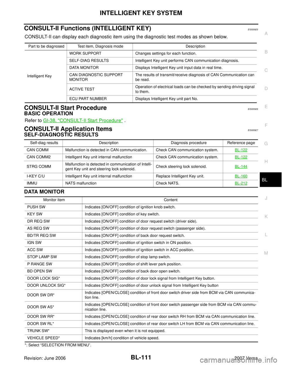
CONSULT-II Functions (INTELLIGENT KEY)EIS00925
CONSULT-II can display each diagnostic item using the diagnostic test modes as shown below.
CONSULT-II Start ProcedureEIS00926
BASIC OPERATION
Refer to GI-38, "CONSULT-II Start Procedure" .
CONSULT-II Application ItemsEIS00927
SELF-DIAGNOSTIC RESULTS
DATA MONITOR
*: Select “SELECTION FROM MENU”.Part to be diagnosed Test item, Diagnosis mode Description
Intelligent KeyWORK SUPPORT Changes settings for each function.
SELF-DIAG RESULTS Intelligent Key unit performs CAN communication diagnosis.
DATA MONITOR Displays Intelligent Key unit input data in real time.
CAN DIAGNOSTIC SUPPORT
MONITORThe results of transmit/receive diagnosis of CAN Communication can
be read.
ACTIVE TESTOperation of electrical loads can be checked by sending driving signal
to them.
ECU PART NUMBER Displays Intelligent Key unit part No.
Self-diag results Description Diagnosis procedure Reference page
CAN COMM Malfunction is detected in CAN communication. Check CAN communication system.BL-122
CAN COMM2 Intelligent Key unit internal malfunction Check CAN communication system.BL-122
STRG COMMMalfunction is detected in communication of Intelli-
gent Key unit and steering lock solenoid.Check steering lock solenoid.BL-144
I-KEY C/U Intelligent Key unit internal malfunction Replace Intelligent Key unit.BL-160
IMMU NATS malfunction Check NATS.BL-212
Monitor item Content
PUSH SW Indicates [ON/OFF] condition of ignition knob switch.
KEY SW Indicates [ON/OFF] condition of key switch.
DR REQ SW Indicates [ON/OFF] condition of door request switch (driver side).
AS REQ SW Indicates [ON/OFF] condition of door request switch (passenger side).
BD/TR REQ SW Indicates [ON/OFF] condition of back door request switch.
IGN SW Indicates [ON/OFF] condition of ignition switch in ON position.
ACC SW Indicates [ON/OFF] condition of ignition switch in ACC position.
STOP LAMP SW Indicates [ON/OFF] condition of stop lamp switch.
P RANGE SW Indicates [ON/OFF] condition of shift lever park position.
BD OPEN SW Indicates [ON/OFF] condition of back door open switch.
DOOR LOCK SIG* Indicates [ON/OFF] condition of door lock signal from Intelligent Key button.
DOOR UNLOCK SIG* Indicates [ON/OFF] condition of door unlock signal from Intelligent Key button
DOOR SW DR*Indicates [OPEN/CLOSE] condition of front door switch driver side from BCM via CAN communica-
tion line.
DOOR SW AS*Indicates [OPEN/CLOSE] condition of front door switch passenger side from BCM via CAN commu-
nication line.
DOOR SW RR* Indicates [OPEN/CLOSE] condition of rear door switch RH from BCM via CAN communication line.
DOOR SW RL* Indicates [OPEN/CLOSE] condition of rear door switch LH from BCM via CAN communication line.
TRUNK SW* This is displayed even when it is not equipped.
VEHICLE SPEED* Indicates [km/h] condition of vehicle speed.
Page 603 of 2896
BL-114
INTELLIGENT KEY SYSTEM
Revision: June 20062007 Versa
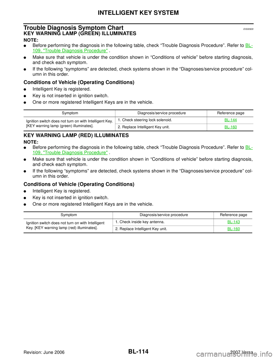
Trouble Diagnosis Symptom ChartEIS00928
KEY WARNING LAMP (GREEN) ILLUMINATES
NOTE:
�Before performing the diagnosis in the following table, check “Trouble Diagnosis Procedure”. Refer to BL-
109, "Trouble Diagnosis Procedure" .
�Make sure that vehicle is under the condition shown in “Conditions of vehicle” before starting diagnosis,
and check each symptom.
�If the following “symptoms” are detected, check systems shown in the “Diagnoses/service procedure” col-
umn in this order.
Conditions of Vehicle (Operating Conditions)
�Intelligent Key is registered.
�Key is not inserted in ignition switch.
�One or more registered Intelligent Keys are in the vehicle.
KEY WARNING LAMP (RED) ILLUMINATES
NOTE:
�Before performing the diagnosis in the following table, check “Trouble Diagnosis Procedure”. Refer to BL-
109, "Trouble Diagnosis Procedure" .
�Make sure that vehicle is under the condition shown in “Conditions of vehicle” before starting diagnosis,
and check each symptom.
�If the following “symptoms” are detected, check systems shown in the “Diagnoses/service procedure” col-
umn in this order.
Conditions of Vehicle (Operating Conditions)
�Intelligent Key is registered.
�Key is not inserted in ignition switch.
�One or more registered Intelligent Keys are in the vehicle.
Symptom Diagnosis/service procedure Reference page
Ignition switch does not turn on with Intelligent Key.
[KEY warning lamp (green) illuminates].1. Check steering lock solenoid.BL-144
2. Replace Intelligent Key unit.BL-160
Symptom Diagnosis/service procedure Reference page
Ignition switch does not turn on with Intelligent
Key. [KEY warning lamp (red) illuminates].1. Check inside key antenna.BL-143
2. Replace Intelligent Key unit.BL-160
Page 633 of 2896
BL-144
INTELLIGENT KEY SYSTEM
Revision: June 20062007 Versa
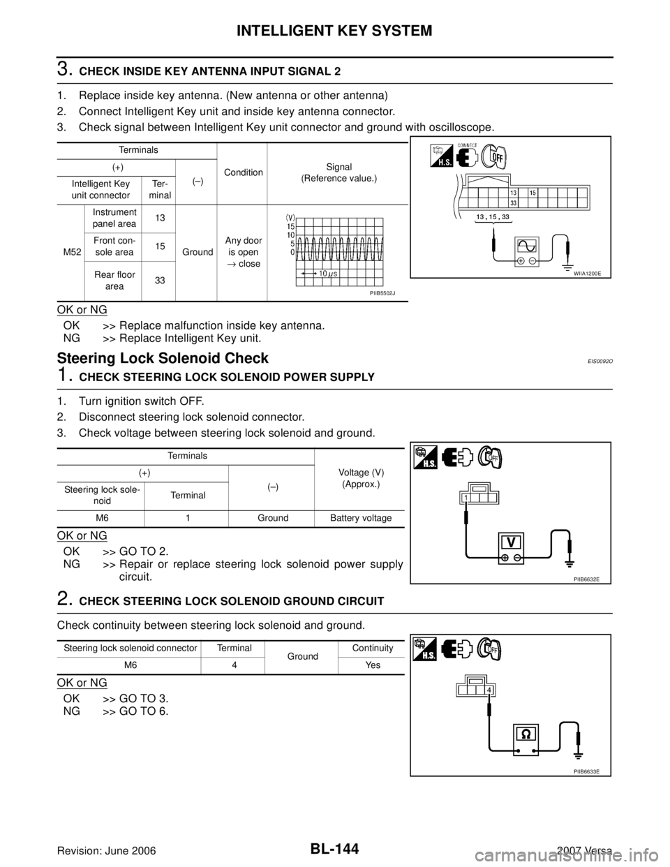
3. CHECK INSIDE KEY ANTENNA INPUT SIGNAL 2
1. Replace inside key antenna. (New antenna or other antenna)
2. Connect Intelligent Key unit and inside key antenna connector.
3. Check signal between Intelligent Key unit connector and ground with oscilloscope.
OK or NG
OK >> Replace malfunction inside key antenna.
NG >> Replace Intelligent Key unit.
Steering Lock Solenoid CheckEIS0092O
1. CHECK STEERING LOCK SOLENOID POWER SUPPLY
1. Turn ignition switch OFF.
2. Disconnect steering lock solenoid connector.
3. Check voltage between steering lock solenoid and ground.
OK or NG
OK >> GO TO 2.
NG >> Repair or replace steering lock solenoid power supply
circuit.
2. CHECK STEERING LOCK SOLENOID GROUND CIRCUIT
Check continuity between steering lock solenoid and ground.
OK or NG
OK >> GO TO 3.
NG >> GO TO 6.
Te r m i n a l s
ConditionSignal
(Reference value.) (+)
(–)
Intelligent Key
unit connectorTe r -
minal
M52Instrument
panel area13
GroundAny door
is open
→ close Front con-
sole area15
Rear floor
area33
WIIA1200E
PIIB5502J
Te r m i n a l s
Voltage (V)
(Approx.) (+)
(–)
Steering lock sole-
noidTerminal
M6 1 Ground Battery voltage
PIIB6632E
Steering lock solenoid connector Terminal
GroundContinuity
M6 4 Yes
PIIB6633E
Page 634 of 2896
INTELLIGENT KEY SYSTEM
BL-145
C
D
E
F
G
H
J
K
L
MA
B
BL
Revision: June 20062007 Versa
3. CHECK INTELLIGENT KEY UNIT OUTPUT SIGNAL
1. Connect steering lock solenoid connector.
2. Check voltage between Intelligent Key unit and ground.
OK or NG
OK >> GO TO 4.
NG >> Replace Intelligent Key unit. Refer to BL-160, "
Removal
and Installation of Intelligent Key Unit" .
4. CHECK STEERING LOCK COMMUNICATION SIGNAL
Check signal between Intelligent Key unit and ground with oscilloscope.
OK or NG
OK >> GO TO 5.
NG >> Replace Intelligent Key unit. Refer to BL-160, "
Removal and Installation of Intelligent Key Unit" .
Te r m i n a l s
Voltage (V)
(Approx.) (+)
(–)
Intelligent Key unit
connectorTe r m i n a l
M52 1 Ground 5
PIIB6634E
Te r m i n a l s
Condition of
key switchVoltage (V)
(Approx.) (+)
(–) Intelligent
Key unit
connectorTe r m i n a l
M52 32 GroundIgnition
switch is
pressed,
when Intelli-
gent Key is
into the vehi-
cle.
Other than
above5
PIIB6635E
SIIA1911J
Page 635 of 2896
BL-146
INTELLIGENT KEY SYSTEM
Revision: June 20062007 Versa
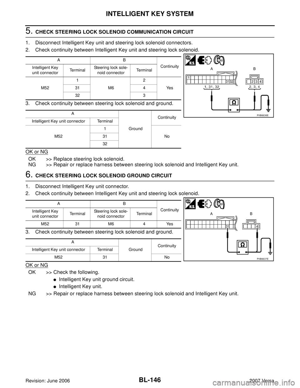
5. CHECK STEERING LOCK SOLENOID COMMUNICATION CIRCUIT
1. Disconnect Intelligent Key unit and steering lock solenoid connectors.
2. Check continuity between Intelligent Key unit and steering lock solenoid.
3. Check continuity between steering lock solenoid and ground.
OK or NG
OK >> Replace steering lock solenoid.
NG >> Repair or replace harness between steering lock solenoid and Intelligent Key unit.
6. CHECK STEERING LOCK SOLENOID GROUND CIRCUIT
1. Disconnect Intelligent Key unit connector.
2. Check continuity between Intelligent Key unit and steering lock solenoid.
3. Check continuity between steering lock solenoid and ground.
OK or NG
OK >> Check the following.
�Intelligent Key unit ground circuit.
�Intelligent Key unit.
NG >> Repair or replace harness between steering lock solenoid and Intelligent Key unit.
AB
Continuity
Intelligent Key
unit connectorTe r m i n a lSteering lock sole-
noid connectorTe r m i n a l
M521
M62
Ye s 31 4
32 3
A
GroundContinuity
Intelligent Key unit connector Terminal
M521
No 31
32
PIIB6636E
AB
Continuity
Intelligent Key
unit connectorTe r m i n a lSteering lock sole-
noid connectorTe r m i n a l
M52 31 M6 4 Yes
A
GroundContinuity
Intelligent Key unit connector Terminal
M52 31 No
PIIB6637E
Page 701 of 2896
BL-212
NATS (NISSAN ANTI-THEFT SYSTEM)
Revision: June 20062007 Versa
NATS (NISSAN ANTI-THEFT SYSTEM)PFP:28591
Component Parts and Harness Connector LocationEIS0093N
LIIA2596E
1. BCM M18, M19, M20
(view with glove box removed)2. Intelligent Key unit M52
(if equipped)3. NATS antenna amp. M21
(inside steering column)
4. Combination meter M24 5. Security indicator lamp 6. ECM E16
Page 788 of 2896
NOISE, VIBRATION AND HARSHNESS (NVH) TROUBLESHOOTING
BR-5
C
D
E
G
H
I
J
K
L
MA
B
BR
Revision: June 20062007 Versa
NOISE, VIBRATION AND HARSHNESS (NVH) TROUBLESHOOTINGPFP:00003
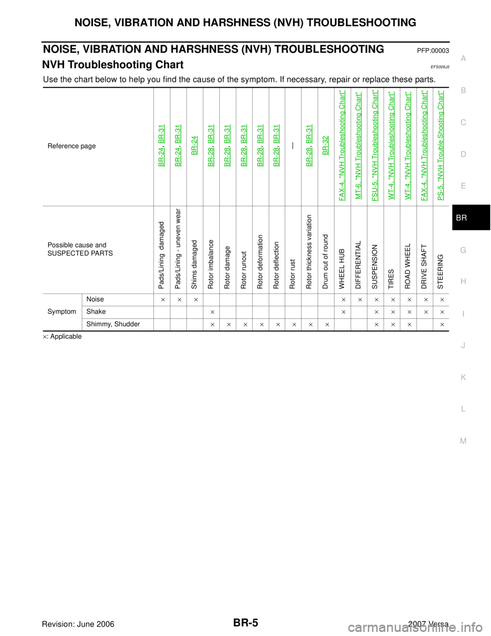
NVH Troubleshooting ChartEFS006J5
Use the chart below to help you find the cause of the symptom. If necessary, repair or replace these parts.
×: ApplicableReference page
BR-24
, BR-31
BR-24
, BR-31BR-24
BR-28
, BR-31
BR-28
, BR-31
BR-28
, BR-31
BR-28
, BR-31
BR-28
, BR-31—
BR-28, BR-31BR-32
FA X-4, "
NVH Troubleshooting Chart
"
MT-6, "
NVH Troubleshooting Chart
"
FSU-5, "
NVH Troubleshooting Chart
"
WT-4, "
NVH Troubleshooting Chart
"
WT-4, "
NVH Troubleshooting Chart
"
FA X-4, "
NVH Troubleshooting Chart
"
PS-5, "
NVH Trouble Shooting Chart
"
Possible cause and
SUSPECTED PARTS
Pads/Lining damaged
Pads/Lining - uneven wear
Shims damaged
Rotor imbalance
Rotor damage
Rotor runout
Rotor deformation
Rotor deflection
Rotor rust
Rotor thickness variation
Drum out of round
WHEEL HUB
DIFFERENTIAL
SUSPENSION
TIRES
ROAD WHEEL
DRIVE SHAFT
STEERING
SymptomNoise××× ×××××××
Shake× × ×××××
Shimmy, Shudder×××××××× ××× ×