Page 90 of 2896
TROUBLE DIAGNOSIS
AT-77
D
E
F
G
H
I
J
K
L
MA
B
AT
Revision: June 20062007 Versa
OthersATF shoots out during
operation.
White smoke emitted
from exhaust pipe
during operation.ON vehicle 1. A/T fluid levelAT- 1 6
OFF vehicle2. Reverse clutchAT- 3 0 9
3. High clutchAT- 3 1 4
4. Brake bandAT- 3 4 3
5. Forward clutchAT- 3 2 0
6. Overrun clutchAT- 3 2 0
7. Low & reverse brakeAT- 3 2 7
Unusual smell at A/T
fluid charging pipe.ON vehicle 1. A/T fluid levelAT- 1 6
OFF vehicle2. Torque converterAT- 2 6 8
3. Oil pumpAT- 2 8 9
4. Reverse clutchAT- 3 0 9
5. High clutchAT- 3 1 4
6. Brake bandAT- 3 4 3
7. Forward clutchAT- 3 2 0
8. Overrun clutchAT- 3 2 0
9. Low & reverse brakeAT- 3 2 7
Items Symptom Condition Diagnostic item Reference page
Page 92 of 2896

TROUBLE DIAGNOSIS
AT-79
D
E
F
G
H
I
J
K
L
MA
B
AT
Revision: June 20062007 Versa
*1: These terminals are connected to the data link connector.*2: These terminals are connected to the ECM.26 Y PNP switch “1” position
and When setting selector lever to “1” posi-
tion.Battery voltage
When setting selector lever to other
positions.0 V
27 G PNP switch “2” positionWhen setting selector lever to “2” posi-
tion.Battery voltage
When setting selector lever to other
positions.0 V
28 GRPower supply
(memory back-up)Always Battery voltage
29 V Revolution sensor When driving at 20 km/h (12 MPH) 150 Hz
30
*1BR CONSULT- II (RX) — —
31
*1Y CONSULT- II (TX) — —
34 LG PNP switch “D” position
and When setting selector lever to “D” posi-
tion.Battery voltage
When setting selector lever to other
positions.0 V
35 SB PNP switch “R” positionWhen setting selector lever to “R” posi-
tion.Battery voltage
When setting selector lever to other
positions.0 V
36 RPNP switch “N” or “P”
positionWhen setting selector lever to “N” or
“P” position.Battery voltage
When setting selector lever to other
positions.0 V
38 GTurbine revolution sen-
sor (power train revolu-
tion sensor)When driving at 20 km/h (12 MPH) 360 Hz
39
*2L Engine speed signal
and Refer to EC-105 .
40 O Vehicle speed sensorWhen driving vehicle at 2 to 3 km/h (1
to 2 MPH) for 1 m (3 ft) or more.Voltage varies
between less
than 0 V and
more than 4.5 V
42 B Sensor ground Always 0 V
47 BRA/T fluid temperature
sensor
and When A/T fluid temperature is 20°C
(68°F).1.5 V
When A/T fluid temperature is 80°C
(176°F).0.5 V
48 B Ground Always 0 V Te r m i n a lWire
colorItem ConditionJudgement stan-
dard (Approx.)
Page 93 of 2896
UCS005N1
CONSULT-II can display each diagnostic item using the diagnostic test models shown following.
FUNCTION
CONSULT-I")
AT-80
TROUBLE DIAGNOSIS
Revision: June 20062007 Versa
CONSULT-II Function (A/T)UCS005N1
CONSULT-II can display each diagnostic item using the diagnostic test models shown following.
FUNCTION
CONSULT-II REFERENCE VALUE
NOTICE:
1. The CONSULT-II electrically displays shift timing and lock-up timing (that is, operation timing of each sole-
noid).
Check for time difference between actual shift timing and the CONSULT-II display. If the difference is
noticeable, mechanical parts (except solenoids, sensors, etc.) may be malfunctioning. Check mechanical
parts using applicable diagnostic procedures.
2. Shift schedule (which implies gear position) displayed on CONSULT-II and that indicated in Service Man-
ual may differ slightly. This occurs because of the following reasons:
–Actual shift schedule has more or less tolerance or allowance,
–Shift schedule indicated in Service Manual refers to the point where shifts start, and
–Gear position displayed on CONSULT-II indicates the point where shifts are completed.
3. Shift solenoid valve “A” or “B” is displayed on CONSULT-II at the start of shifting. Gear position is dis-
played upon completion of shifting (which is computed by TCM).
Diagnostic test mode Function Reference page
Work supportThis mode enables a technician to adjust some devices faster and more accurately by
following the indications on CONSULT-II.—
Self-diagnostic results Self-diagnostic results can be read and erased quickly.AT- 8 2
Data monitor Input/Output data in the TCM can be read.AT- 8 4
CAN diagnostic support
monitorThe results of transmit/receive diagnosis of CAN communication can be read.AT- 8 6
Function testPerformed by CONSULT-II instead of a technician to determine whether each system
is “OK” or “NG”.—
DTC work support Select the operating condition to confirm Diagnostic Trouble Codes.AT- 8 6
TCM part number TCM part number can be read. —
Item name Condition Display value (Approx.)
VHCL/S SE-A/T
During drivingApproximately matches the speedometer
reading.
VHCL/S SE-MTR
THROTTLE POSIReleased accelerator pedal. 0.0/8
Fully depressed accelerator pedal. 8.0/8
FLUID TEMP SE When A/T fluid temperature is 20°C (68°F). 1.5 V
When A/T fluid temperature is 80°C (176°F). 0.5 V
BATTERY VOLT When turning ignition switch to “ON”. Battery voltage
ENGINE SPEED Engine runningApproximately matches the tachometer
reading.
TURBINE REV During driving (lock-up ON) Approximately matches the engine speed.
OVERDRIVE SWWhen overdrive control switch is depressed. ON
When overdrive control switch is released. OFF
PN POSI SWWhen setting selector lever to “N” or “P” posi-
tion.ON
When setting selector lever to other positions. OFF
R POSITION SWWhen setting selector lever to “R” position. ON
When setting selector lever to other positions. OFF
D POSITION SWWhen setting selector lever to “D” position. ON
When setting selector lever to other positions. OFF
Page 96 of 2896
TROUBLE DIAGNOSIS
AT-83
D
E
F
G
H
I
J
K
L
MA
B
AT
Revision: June 20062007 Versa
*1: Refer to AT- 4 2 , "Malfunction Indicator Lamp (MIL)" .
*2: These malfunctions cannot be displayed MIL if another malfunction is assigned to MIL.
How to Erase Self-diagnostic Results
1. Touch “SELF-DIAG RESULTS” on “SELECT DIAG MODE”
screen.
2. Touch “ERASE”. (The self-diagnostic results will be erased.)
BATT/FLUID TEMP
SEN�TCM receives an excessively low or high voltage from the sensor. —AT- 1 7 0
TURBINE SENSOR�TCM does not receive proper voltage signal from sensor. —AT- 1 7 6
CONTROL UNIT (RAM)�TCM memory (RAM) is malfunctioning. —AT- 1 8 2
CONTROL UNIT (ROM)�TCM memory (ROM) is malfunctioning. —AT- 1 8 2
No failure
(NO SELF DIAGNOS-
TIC FAILURE INDI-
CATED FURTHER
TESTING MAY BE
REQUIRED)
�No failure has been detected. — — Items (CONSULT-II
screen terms)Malfunction is detected when...OBD-II (DTC)
Reference
page MIL indicator
lamp*1,
“ENGINE” with
CONSULT-II or
GST
BCIA0031E
SCIA4849E
Page 97 of 2896

AT-84
TROUBLE DIAGNOSIS
Revision: June 20062007 Versa
DATA MONITOR MODE
Operation Procedure
1. Touch “DATA MONITOR” on “SELECT DIAG MODE” screen.
NOTE:
When malfunction is detected, CONSULT-II performs
“REAL-TIME DIAGNOSIS”. Also, any malfunction detected
while in this mode will be displayed in real time.
Display Items List
X: Standard, —: Not applicable, : Option
BCIA0031E
Monitored item (Unit)Monitor Item Selection
Remarks
TCM INPUT
SIGNALSMAIN SIG-
NALSSELEC-
TION FROM
MENU
VHCL/S SE-A/T (km/h) X — Revolution sensor
VHCL/S SE-MTR (km/h) X —Vehicle speed display may not be accu-
rate under approx. 10 km/h (6 mph). It
may not indicate 0 km/h (0 mph) when
vehicle is stationary.
THRTL POS SEN (V) X —
FLUID TEMP SE (V) X —
BATTERY VOLT (V) X —
ENGINE SPEED (rpm) X X
TURBINE REV (rpm) X —
OVERDRIVE SW (ON/OFF) X —
PN POSI SW (ON/OFF) X —
R POSITION SW (ON/OFF) X —
D POSITION SW (ON/OFF) X —
2 POSITION SW (ON/OFF) X —
1 POSITION SW (ON/OFF) X —
ASCD-CRUISE (ON/OFF) X —
Signal input with CAN communication.
ASCD-OD CUT (ON/OFF) X —
KICKDOWN SW (ON/OFF) X —
Not mounted but displayed.
POWERSHIFT SW (ON/OFF) X —
CLOSED THL/SW (ON/OFF) X —
Signal input with CAN communication.
W/O THRL/P-SW (ON/OFF) X —
*SHIFT S/V A (ON/OFF) — —
Displays status of check signal (reinput
signal) for TCM control signal output.
Remains unchanged when solenoid
valves are open or shorted. *SHIFT S/V B (ON/OFF) — —
*OVRRUN/C S/V (ON/OFF) — —
HOLD SW (ON/OFF) X — Not mounted but displayed.
Page 105 of 2896
AT-92
TROUBLE DIAGNOSIS
Revision: June 20062007 Versa
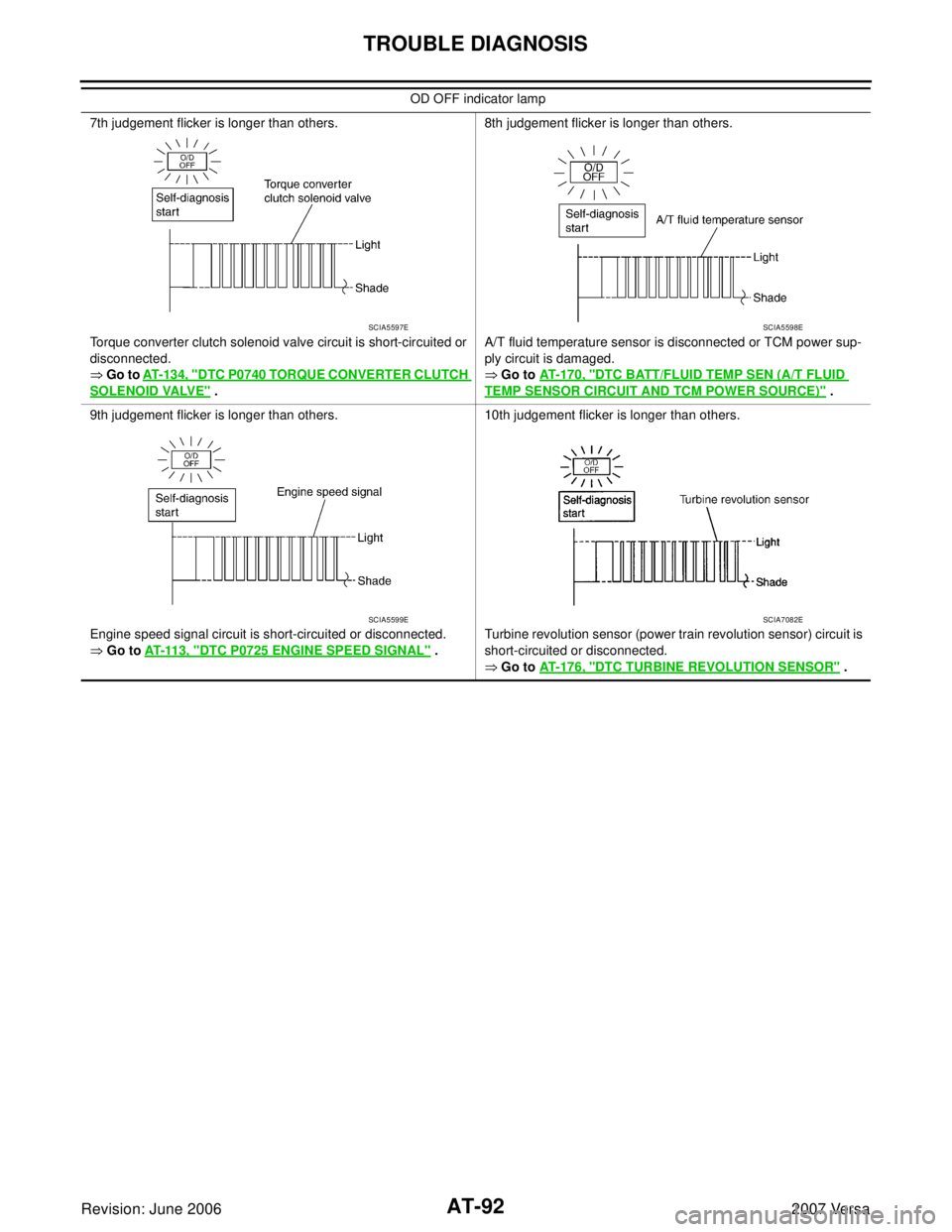
7th judgement flicker is longer than others.
Torque converter clutch solenoid valve circuit is short-circuited or
disconnected.
� Go to AT- 1 3 4 , "DTC P0740 TORQUE CONVERTER CLUTCH
SOLENOID VALVE" .8th judgement flicker is longer than others.
A/T fluid temperature sensor is disconnected or TCM power sup-
ply circuit is damaged.
� Go to AT-170, "DTC BATT/FLUID TEMP SEN (A/T FLUID
TEMP SENSOR CIRCUIT AND TCM POWER SOURCE)" .
9th judgement flicker is longer than others.
Engine speed signal circuit is short-circuited or disconnected.
� Go to AT-11 3 , "DTC P0725 ENGINE SPEED SIGNAL" .10th judgement flicker is longer than others.
Turbine revolution sensor (power train revolution sensor) circuit is
short-circuited or disconnected.
� Go to AT-176, "DTC TURBINE REVOLUTION SENSOR" . OD OFF indicator lamp
SCIA5597ESCIA5598E
SCIA5599ESCIA7082E
Page 115 of 2896

AT-102
DTC P0710 A/T FLUID TEMPERATURE SENSOR CIRCUIT
Revision: June 20062007 Versa
DTC P0710 A/T FLUID TEMPERATURE SENSOR CIRCUITPFP:31940
DescriptionUCS005NM
The A/T fluid temperature sensor detects the A/T fluid temperature and sends a signal to the TCM.
CONSULT-II Reference ValueUCS005NN
Remarks: Specification data are reference values.
On Board Diagnosis LogicUCS005NO
�This is an OBD-II self-diagnostic item.
�Diagnostic trouble code “P0710 ATF TEMP SEN/CIRC” with CONSULT-II is detected when TCM receives
an excessively low or high voltage from the sensor.
Possible CauseUCS005NP
�Harness or connector
(The sensor circuit is open or shorted.)
�A/T fluid temperature sensor
DTC Confirmation ProcedureUCS005NQ
CAUTION:
�Always drive vehicle at a safe speed.
�If performing this “DTC Confirmation Procedure” again, always turn ignition switch OFF and wait
at least 10 seconds before continuing.
After the repair, perform the following procedure to confirm the malfunction is eliminated.
WITH CONSULT-II
1. Turn ignition switch ON and select “DATA MONITOR” mode for
“A/T” with CONSULT-II.
2. Touch “START”.
3. Start engine and maintain the following conditions for at least 10
minutes (Total). (It is not necessary to maintain continuously.)
ENGINE SPEED: 450 rpm or more
VEHICLE SPEED: 10 km/h (6 MPH) or more
THROTTLE POSI: More than 1.0/8
SLCT LVR POSI: “D” position
4. If the check result is NG, go to AT-104, "
Diagnostic Procedure" .
WITH GST
Follow the procedure “With CONSULT-II”.
Item name Condition Display value (Approx.)
FLUID TEMP SEWhen A/T fluid temperature is 20°C (68°F). 1.5 V
When A/T fluid temperature is 80°C (176°F). 0.5 V
BCIA0031E
Page 116 of 2896
DTC P0710 A/T FLUID TEMPERATURE SENSOR CIRCUIT
AT-103
D
E
F
G
H
I
J
K
L
MA
B
AT
Revision: June 20062007 Versa
Wiring Diagram — AT — FTSUCS005N R
BCWA0650E

\" .
*2: These malfunctions cannot be displayed MIL if another m")