Page 228 of 2896

TROUBLE DIAGNOSIS FOR SYMPTOMS
AT-215
D
E
F
G
H
I
J
K
L
MA
B
AT
Revision: June 20062007 Versa
A/T Does Not Hold Lock-up ConditionUCS005V8
SYMPTOM:
A/T does not hold lock-up condition for more than 30 seconds on “Cruise Test — Part 1”.
DIAGNOSTIC PROCEDURE
1. CHECK SELF-DIAGNOSTIC RESULTS
Perform self-diagnosis. Refer to AT-82, "
SELF-DIAGNOSTIC RESULT MODE" or AT-90, "Diagnostic Proce-
dure Without CONSULT-II" .
Is any malfunction detected by self-diagnostic results?
YES >> Check the malfunctioning system. Refer to AT- 8 2 , "SELF-DIAGNOSTIC RESULT MODE" or AT-
91, "Judgement of Self-diagnosis Code" .
NO >> GO TO 2.
2. CHECK A/T FLUID CONDITION
1. Remove oil pan. Refer to AT-257, "
Components" .
2. Check A/T fluid condition. Refer to AT-53, "
Fluid Condition Check" .
OK or NG
OK >> GO TO 4.
NG >> GO TO 3.
3. DETECT MALFUNCTIONING ITEM
1. Remove control valve assembly. Refer to AT-242, "
Control Valve Assembly and Accumulators" .
2. Check the following items:
–Torque converter clutch control valve
–Torque converter clutch solenoid valve
–Pilot valve
–Pilot filter
3. Disassemble A/T. Refer to AT- 2 6 8 , "
Disassembly" .
4. Check the following items:
–Torque converter. Refer to AT- 2 6 8 , "Disassembly" .
–Oil pump assembly. Refer to AT-289, "Oil Pump" .
OK or NG
OK >> GO TO 5.
NG >> Repair or replace damaged parts.
4. DETECT MALFUNCTIONING ITEM
1. Remove control valve assembly. Refer to AT-242, "
Control Valve Assembly and Accumulators" .
2. Check the following items:
–Torque converter clutch control valve
–Torque converter clutch solenoid valve
–Pilot valve
–Pilot filter
OK or NG
OK >> GO TO 5.
NG >> Repair or replace damaged parts.
Page 230 of 2896
UCS005VA
SYMPTOM:
Engine speed does not sm")
TROUBLE DIAGNOSIS FOR SYMPTOMS
AT-217
D
E
F
G
H
I
J
K
L
MA
B
AT
Revision: June 20062007 Versa
Engine Speed Does Not Return to Idle (Light Braking D4 → D3 )UCS005VA
SYMPTOM:
Engine speed does not smoothly return to idle when A/T shifts from D4 to D3 on “Cruise Test — Part
1”.
DIAGNOSTIC PROCEDURE
1. CHECK SELF-DIAGNOSTIC RESULTS
Perform self-diagnosis. Refer to AT-82, "
SELF-DIAGNOSTIC RESULT MODE" or AT-90, "Diagnostic Proce-
dure Without CONSULT-II" .
Is any malfunction detected by self-diagnostic results?
YES >> Check the malfunctioning system. Refer to AT- 8 2 , "SELF-DIAGNOSTIC RESULT MODE" or AT-
91, "Judgement of Self-diagnosis Code" .
NO >> GO TO 2.
2. CHECK ACCELERATOR PEDAL POSITION SENSOR
Check accelerator pedal position sensor. Refer to EC-532, "
DTC P2138 APP SENSOR" .
OK or NG
OK >> GO TO 3.
NG >> Repair or replace accelerator pedal position sensor.
3. CHECK A/T FLUID CONDITION
1. Remove oil pan. Refer to AT-257, "
Components" .
2. Check A/T fluid condition. Refer to AT-53, "
Fluid Condition Check" .
OK or NG
OK >> GO TO 5.
NG >> GO TO 4.
4. DETECT MALFUNCTIONING ITEM
1. Remove control valve assembly. Refer to AT-242, "
Control Valve Assembly and Accumulators" .
2. Check the following items:
–Overrun clutch control valve
–Overrun clutch reducing valve
–Overrun clutch solenoid valve
3. Disassemble A/T. Refer to AT- 2 6 8 , "
Disassembly" .
4. Check the following items:
–Overrun clutch assembly. Refer to AT-320, "Forward and Overrun Clutches" .
OK or NG
OK >> GO TO 6.
NG >> Repair or replace damaged parts.
5. DETECT MALFUNCTIONING ITEM
1. Remove control valve assembly. Refer to AT-242, "
Control Valve Assembly and Accumulators" .
2. Check the following items:
–Overrun clutch control valve
–Overrun clutch reducing valve
–Overrun clutch solenoid valve
OK or NG
OK >> GO TO 6.
NG >> Repair or replace damaged parts.
Page 235 of 2896

2. Check voltage between TCM conn")
AT-222
TROUBLE DIAGNOSIS FOR SYMPTOMS
Revision: June 20062007 Versa
2. CHECK PNP SWITCH CIRCUIT
Without CONSULT-II
1. Turn ignition switch ON. (Do not start engine.)
2. Check voltage between TCM connector terminals and ground
while moving selector lever through each position. Refer to AT-
98, "Wiring Diagram — AT — PNP/SW" .
B: Battery voltage
0: 0V
OK or NG
OK >> GO TO 3
NG >> Check PNP switch. Refer to AT - 1 9 1 , "
PNP SWITCH" .
3. CHECK A/T POSITION
Check A/T position. Refer to AT-234, "
Checking of A/T Position" .
OK or NG
OK >> GO TO 4.
NG >> Adjust A/T position. Refer to AT- 2 3 3 , "
Adjustment of A/T Position" .
4. CHECK VEHICLE SPEED SENSOR·A/T AND VEHICLE SPEED SENSOR·MTR CIRCUIT
Check vehicle speed sensor·A/T (revolution sensor) and vehicle speed sensor·MTR circuit. Refer to AT-107,
"DTC P0720 VEHICLE SPEED SENSOR·A/T (REVOLUTION SENSOR)" and/or AT-166, "DTC VEHICLE
SPEED SENSOR MTR" .
OK or NG
OK >> GO TO 5.
NG >> Repair or replace vehicle speed sensor·A/T (revolution sensor) and/or vehicle speed sensor·MTR
circuits.
5. CHECK A/T FLUID CONDITION
1. Remove oil pan. Refer to AT-257, "
Components" .
2. Check A/T fluid condition. Refer to AT- 5 3 , "
Fluid Condition Check" .
OK or NG
OK >> GO TO 7.
NG >> GO TO 6.
Selector lever positionTerminal
36 35 34 27 26
“P”, “N” B 0 0 0 0
“R” 0B000
“D” 0 0 B 0 0
“2” 0 0 0 B 0
“1” 0 0 0 0 B
SCIA7162E
Page 239 of 2896

AT-226
TROUBLE DIAGNOSIS FOR SYMPTOMS
Revision: June 20062007 Versa
5. CHECK A/T POSITION
Check A/T position. Refer to AT-234, "
Checking of A/T Position" .
OK or NG
OK >> GO TO 6.
NG >> Adjust A/T position. Refer to AT- 2 3 3 , "
Adjustment of A/T Position" .
6. CHECK VEHICLE SPEED SENSOR·A/T AND VEHICLE SPEED SENSOR·MTR CIRCUIT
Check vehicle speed sensor·A/T (revolution sensor) and vehicle speed sensor·MTR circuit. Refer to AT-107,
"DTC P0720 VEHICLE SPEED SENSOR·A/T (REVOLUTION SENSOR)" and/or AT-166, "DTC VEHICLE
SPEED SENSOR MTR" .
OK or NG
OK >> GO TO 7.
NG >> Repair or replace vehicle speed sensor·A/T (revolution sensor) and/or vehicle speed sensor·MTR
circuits.
7. CHECK ACCELERATOR PEDAL POSITION SENSOR
Check accelerator pedal position sensor. Refer to EC-532, "
DTC P2138 APP SENSOR" .
OK or NG
OK >> GO TO 8.
NG >> Repair or replace accelerator pedal position sensor.
8. CHECK A/T FLUID CONDITION
1. Remove oil pan. Refer to AT-257, "
Components" .
2. Check A/T fluid condition. Refer to AT- 5 3 , "
Fluid Condition Check" .
OK or NG
OK >> GO TO 10.
NG >> GO TO 9.
9. DETECT MALFUNCTIONING ITEM
1. Remove control valve assembly. Refer to AT-242, "
Control Valve Assembly and Accumulators" .
2. Check the following.
–Shift valve A
–Overrun clutch solenoid valve
3. Disassemble A/T. Refer to AT-268, "
Disassembly" .
4. Check the following.
–Overrun clutch assembly. Refer to AT-320, "Forward and Overrun Clutches" .
–Low & reverse brake assembly. Refer to AT-327, "Low & Reverse Brake" .
OK or NG
OK >> GO TO 10.
NG >> Repair or replace damaged parts.
10. CHECK SYMPTOM
Check again. Refer to AT-65, "
Cruise Test — Part 3" .
OK or NG
OK >>INSPECTION END
NG >> GO TO 11.
Page 255 of 2896

AT-242
ON-VEHICLE SERVICE
Revision: June 20062007 Versa
ON-VEHICLE SERVICEPFP:00000
Control Valve Assembly and AccumulatorsUCS005VR
COMPONENTS
REMOVAL AND INSTALLATION
Removal
1. Disconnect the battery negative terminal.
2. Remove engine under cover and fender protector (LH). Refer to EI-22, "
Removal and Installation" .
3. Drain the A/T fluid. Refer to AT-16, "
A/T FLUID" .
4. Remove oil pan and oil pan gasket.
5. Check for foreign materials in oil pan to help determine cause of
malfunction. If the ATF is very dark, smell burned or contains for-
eign particles, friction material (clutches, band) may need
replacement. A tacky film that will not wipe clean indicates var-
nish build up. Varnish can cause valves, servo, and clutches to
stick and can inhibit pump pressure.
�If ATF contains frictional material (clutch, bands, etc.),
replace radiator and flush cooler line using cleaning sol-
vent and compressed air after repair of A/T. Refer to CO-
11, "RADIATOR" .
6. Remove magnets from oil pan.
1. A/T 2. O-ring 3. Return spring
4. Control valve assembly 5. Oil pan gasket 6. Oil pan
7. Drain plug gasket 8. Drain plug 9. Magnet
10. Oil pan fitting bolt 11. Snap ring 12. O-ring
13. Servo release accumulator piston 14. N-D accumulator piston 15. O-ring
16. Return spring 17. Lip seal
SCIA8024E
SCIA8025E
Page 258 of 2896

ON-VEHICLE SERVICE
AT-245
D
E
F
G
H
I
J
K
L
MA
B
AT
Revision: June 20062007 Versa
Inspection
�Inspect the sliding surfaces of each accumulator piston and
transaxle case, and replace if damaged or dented.
(1): Servo release accumulator piston
(2): N-D accumulator piston
�Inspect the sliding surfaces of manual valve and valve body, and
replace if damaged or dented.
�Inspect each return spring, and replace if damaged, deformed or
worn. Refer to AT-380, "
Accumulator" for free length (L1 ) and
length (L
2 ).
(1): Return spring (Servo release accumulator)
(2): Return spring (N-D accumulator)
CAUTION:
Do not remove spring retainer (3).
Installation
Installation is in the reverse order of removal.
CAUTION:
�Completely remove all moisture, oil and old gasket from the oil pan gasket mounting surface of
transaxle case and oil pan.
�Do not reuse O-rings, lip seals, oil pan gasket and oil pan bolts.
�Apply ATF to manual valve, O-rings, lip seals and sliding surfaces of the transaxle case.
NOTE:
�Set manual shaft in “N” position, then align manual plate (1) with
groove in manual valve (2).
�After installing control valve assembly to transaxle case, make
sure that selector lever can be moved to all positions.
�After completing installation, check for A/T fluid leakage and A/T
fluid level. Refer to AT- 1 6 , "
Checking A/T Fluid" .
WCIA0652E
SCIA6955E
SCIA7090E
Page 264 of 2896
ON-VEHICLE SERVICE
AT-251
D
E
F
G
H
I
J
K
L
MA
B
AT
Revision: June 20062007 Versa
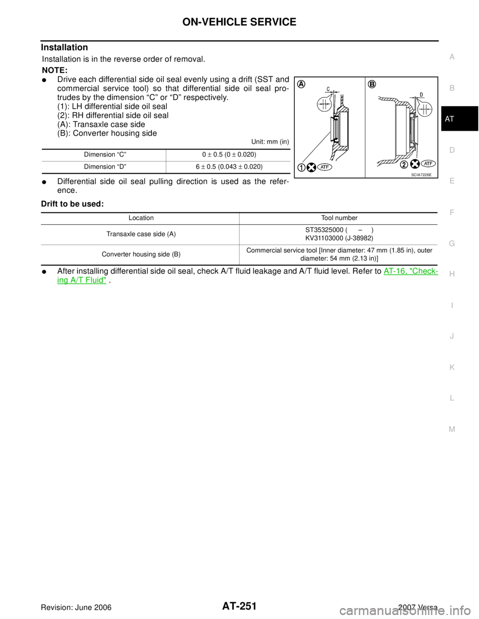
Installation
Installation is in the reverse order of removal.
NOTE:
�Drive each differential side oil seal evenly using a drift (SST and
commercial service tool) so that differential side oil seal pro-
trudes by the dimension “C” or “D” respectively.
(1): LH differential side oil seal
(2): RH differential side oil seal
(A): Transaxle case side
(B): Converter housing side
Unit: mm (in)
�Differential side oil seal pulling direction is used as the refer-
ence.
Drift to be used:
�After installing differential side oil seal, check A/T fluid leakage and A/T fluid level. Refer to AT- 1 6 , "Check-
ing A/T Fluid" .
Dimension “C” 0 ± 0.5 (0 ± 0.020)
Dimension “D” 6 ± 0.5 (0.043 ± 0.020)
SCIA7226E
Location Tool number
Transaxle case side (A)ST35325000 ( – )
KV31103000 (J-38982)
Converter housing side (B)Commercial service tool [Inner diameter: 47 mm (1.85 in), outer
diameter: 54 mm (2.13 in)]
Page 266 of 2896
TRANSAXLE ASSEMBLY
AT-253
D
E
F
G
H
I
J
K
L
MA
B
AT
Revision: June 20062007 Versa
TRANSAXLE ASSEMBLYPFP:32020
Removal and InstallationUCS005VX
COMPONENTS
REMOVAL
1. Remove the engine and transaxle as an assembly. Refer to EM-73, "Removal and Installation" .
1. A/T fluid level gauge 2. A/T fluid charging pipe 3. O-ring
4. Fluid cooler tube 5. Copper washer 6. Bracket
7. Fluid cooler tube 8. A/T assembly 9. Engine mounting bracket (LH)
10. Bracket A. Refer to AT- 2 5 4 , "
INSTALLATION" .
WCIA0646E