Page 2678 of 2896

SC-4
BATTERY
Revision: June 20062007 Versa
BATTERYPFP:AYBGL
How to Handle BatteryEKS00IAY
CAUTION:
�If it becomes necessary to start the engine with a booster battery and jumper cables, use a 12-volt
booster battery.
�After connecting battery cables, ensure that they are tightly clamped to battery terminals for good
contact.
�Never add distilled water through the hole used to check specific gravity.
METHODS OF PREVENTING OVER-DISCHARGE
The following precautions must be taken to prevent over-discharging
a battery.
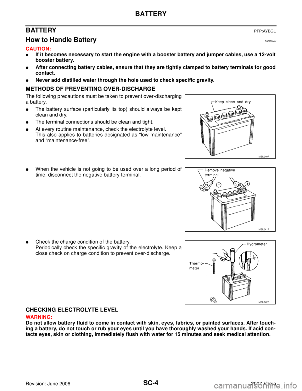
�The battery surface (particularly its top) should always be kept
clean and dry.
�The terminal connections should be clean and tight.
�At every routine maintenance, check the electrolyte level.
This also applies to batteries designated as “low maintenance”
and “maintenance-free”.
�When the vehicle is not going to be used over a long period of
time, disconnect the negative battery terminal.
�Check the charge condition of the battery.
Periodically check the specific gravity of the electrolyte. Keep a
close check on charge condition to prevent over-discharge.
CHECKING ELECTROLYTE LEVEL
WAR NIN G:
Do not allow battery fluid to come in contact with skin, eyes, fabrics, or painted surfaces. After touch-
ing a battery, do not touch or rub your eyes until you have thoroughly washed your hands. If acid con-
tacts eyes, skin or clothing, immediately flush with water for 15 minutes and seek medical attention.
MEL040F
MEL041F
MEL042F
Page 2845 of 2896

REMOVAL AND INSTALLATION
WT-27
C
D
F
G
H
I
J
K
L
MA
B
WT
Revision: June 20062007 Versa
REMOVAL AND INSTALLATIONPFP:00000
Transmitter (Pressure Sensor)EES002EG
REMOVAL
1. Remove wheel and tire using power tool.
2. Deflate tire. Unscrew transmitter retaining nut and allow transmitter to fall into tire.
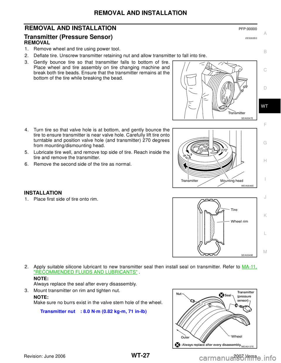
3. Gently bounce tire so that transmitter falls to bottom of tire.
Place wheel and tire assembly on tire changing machine and
break both tire beads. Ensure that the transmitter remains at the
bottom of the tire while breaking the bead.
4. Turn tire so that valve hole is at bottom, and gently bounce the
tire to ensure transmitter is near valve hole. Carefully lift tire onto
turntable and position valve hole (and transmitter) 270 degrees
from mounting/dismounting head.
5. Lubricate tire well, and remove top side of tire. Reach inside the
tire and remove the transmitter.
6. Remove the second side of the tire as normal.
INSTALLATION
1. Place first side of tire onto rim.
2. Apply suitable silicone lubricant to new transmitter seal then install seal on transmitter. Refer to MA-11,
"RECOMMENDED FLUIDS AND LUBRICANTS" .
NOTE:
Always replace the seal after every disassembly.
3. Mount transmitter on rim and tighten nut.
NOTE:
Make sure no burrs exist in the valve stem hole of the wheel.
SEIA0047E
WEIA0046E
SEIA0049E
Transmitter nut : 8.0 N·m (0.82 kg-m, 71 in-lb)
WEIA0137E
Page 2850 of 2896

WW-2Revision: June 20062007 Versa REAR WIPER OPERATION ................................ 31
INTERMITTENT OPERATION ............................ 31
AUTO STOP OPERATION .................................. 31
REAR WASHER OPERATION ............................ 31
BCM WIPER SWITCH READING FUNCTION .... 32
Wiring Diagram — WIP/R — .................................. 33
Terminals and Reference Values for BCM .............. 35
How to Proceed With Trouble Diagnosis ................ 35
Preliminary Check .................................................. 35
CHECK POWER SUPPLY AND GROUND CIR-
CUIT FOR BCM ................................................... 35
CONSULT-II Function (BCM) .................................. 35
Rear Wiper Does Not Operate ............................... 35
Rear Wiper Stop Position Is Incorrect ..................... 37
Only Rear Wiper Does Not Operate ....................... 38
Only Rear Wiper Intermittent Does Not Operate .... 38
Wiper Does Not Wipe When Rear Washer Operates ... 39
Removal and Installation ........................................ 40REAR WIPER ARM .............................................40
REAR WIPER MOTOR ........................................41
REAR WASHER TUBE LAYOUT .........................42
REAR WASHER NOZZLE ...................................42
WASHER FLUID RESERVOIR ............................43
WIPER AND WASHER SWITCH .........................43
WASHER MOTOR ...............................................43
Washer Nozzle Adjustment .....................................43
POWER SOCKET .....................................................44
Wiring Diagram — P/SCKT — ................................44
Removal and Installation .........................................45
REMOVAL ............................................................45
INSTALLATION ....................................................45
HORN ........................................................................46
Wiring Diagram — HORN — ..................................46
Removal and Installation .........................................47
REMOVAL ............................................................47
INSTALLATION ....................................................47
Page 2872 of 2896

WW-24
FRONT WIPER AND WASHER SYSTEM
Revision: June 20062007 Versa
Removal and Installation of Front Wiper ArmsEKS00I22
REMOVAL
1. Turn wiper switch on to operate wiper motor, and then turn wiper switch off (auto stop).
2. Open hood, remove wiper arm caps, and remove wiper arm nuts.
3. Raise wiper arm, and remove wiper arm from the vehicle.
INSTALLATION
1. Clean up the pivot area as shown. This will reduce possibility of
wiper arm looseness.
2. Prior to wiper arm installation, turn on wiper switch to operate
wiper motor and then turn it off (auto stop).
3. Push wiper arm onto pivot shaft, paying attention to blind spline.
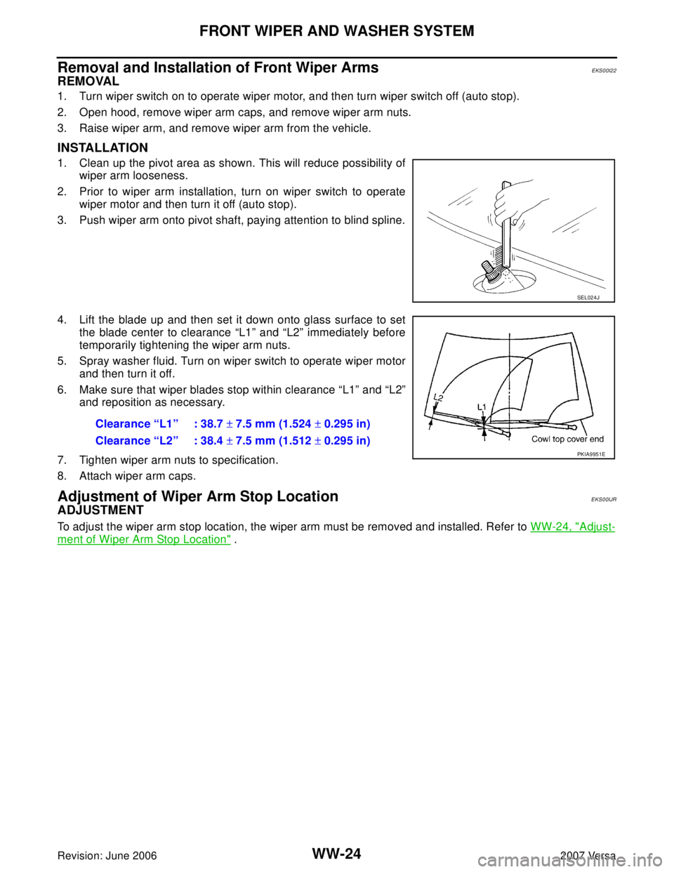
4. Lift the blade up and then set it down onto glass surface to set
the blade center to clearance “L1” and “L2” immediately before
temporarily tightening the wiper arm nuts.
5. Spray washer fluid. Turn on wiper switch to operate wiper motor
and then turn it off.
6. Make sure that wiper blades stop within clearance “L1” and “L2”
and reposition as necessary.
7. Tighten wiper arm nuts to specification.
8. Attach wiper arm caps.
Adjustment of Wiper Arm Stop Location EKS00IJR
ADJUSTMENT
To adjust the wiper arm stop location, the wiper arm must be removed and installed. Refer to WW-24, "Adjust-
ment of Wiper Arm Stop Location" .
SEL024J
Clearance “L1” : 38.7 ± 7.5 mm (1.524 ± 0.295 in)
Clearance “L2” : 38.4 ± 7.5 mm (1.512 ± 0.295 in)
PKIA9951E
Page 2877 of 2896

FRONT WIPER AND WASHER SYSTEM
WW-29
C
D
E
F
G
H
I
J
L
MA
B
WW
Revision: June 20062007 Versa
2. Remove clip (A) and pull washer tank inlet (1) out of washer
tank.
�: Vehicle front
3. Remove the front bumper. Refer to EI-14, "
Removal and Installation" .
4. Disconnect the washer motor connector and washer fluid level sensor connector.
5. Remove the washer tank screw (A).
�: Vehicle front
6. Remove the washer tube (1), and remove washer tank (2) from
the vehicle.
�: Vehicle front
INSTALLATION
Installation is in the reverse order of removal.
CAUTION:
After installation, add water up to the upper level of washer tank inlet, and check for water leaks.
Removal and Installation of Front Washer MotorEKS00I2C
REMOVAL
1. Remove the front fender protector RH. Refer to EI-22, "FENDER PROTECTOR" .
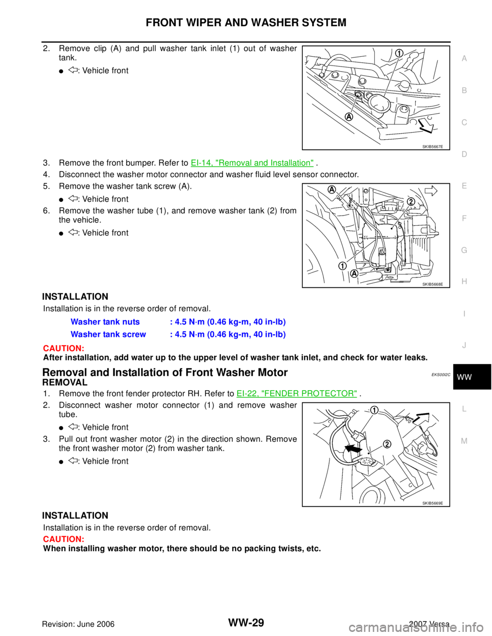
2. Disconnect washer motor connector (1) and remove washer
tube.
�: Vehicle front
3. Pull out front washer motor (2) in the direction shown. Remove
the front washer motor (2) from washer tank.
�: Vehicle front
INSTALLATION
Installation is in the reverse order of removal.
CAUTION:
When installing washer motor, there should be no packing twists, etc.
SKIB5667E
SKIB5668E
Washer tank nuts : 4.5 N·m (0.46 kg-m, 40 in-lb)
Washer tank screw : 4.5 N·m (0.46 kg-m, 40 in-lb)
SKIB5669E
Page 2890 of 2896
WW-42
REAR WIPER AND WASHER SYSTEM
Revision: June 20062007 Versa
REAR WASHER TUBE LAYOUT
NOTE:
Connect the check valve (2) to the washer fluid tube (1) so that the
directional arrow on the check valve (2) points towards the washer
nozzle tube (3).
REAR WASHER NOZZLE
Removal
1. Remove the back door window garnish. Refer to EI-31, "REMOVAL" .
2. Disconnect rear washer tube from rear washer nozzle.
3. Release retaining clips and remove washer nozzle.
1 Washer fluid reservoir 2 Washer fluid tube to rear door 3 Rear washer nozzle
4 Check valve
LKIA0790E
WKIA4242E
LKIA0545E
Page 2891 of 2896
REAR WIPER AND WASHER SYSTEM
WW-43
C
D
E
F
G
H
I
J
L
MA
B
WW
Revision: June 20062007 Versa
Installation
Installation is in the reverse order of removal.
NOTE:
Inspect rear washer nozzle for proper spray pattern, adjust as necessary. Refer to WW-43, "
Washer Nozzle
Adjustment" .
WASHER FLUID RESERVOIR
Refer to WW-28, "Removal and Installation of Washer Tank" .
WIPER AND WASHER SWITCH
Refer to WW-28, "Removal and Installation of Front Wiper and Washer Switch" .
WASHER MOTOR
Refer to WW-29, "Removal and Installation of Front Washer Motor" .
Washer Nozzle AdjustmentEKS00ILU
Adjust the washer nozzle to specification using suitable tool as
shown.
Adjustable range : ±15° (In any direction)
LKIA0349E
WEL912A