Page 267 of 2896
 har-
ness conne")
AT-254
TRANSAXLE ASSEMBLY
Revision: June 20062007 Versa
2. Disconnect the following connectors and remove the wire har-
ness.
�Turbine revolution sensor (power train revolution sensor) har-
ness connector (1)
�Terminal cord assembly harness connector (2)
�PNP switch connector (3)
�Revolution sensor harness connector (4)
3. Remove the four drive plate to torque converter bolts.
NOTE:
Rotate the crankshaft clockwise as viewed from front of engine
for access to drive plate to torque converter bolts.
4. Put matching marks on the drive plate and torque converter.
CAUTION:
For matching marks, use paint. Never damage the drive plate or torque converter.
5. Remove the transaxle to engine and engine to transaxle bolts.
6. Separate the transaxle from the engine.
CAUTION:
Secure torque converter to prevent it from dropping.
7. If necessary, remove the following from the transaxle:
�Fluid cooler tubes (1) and copper washers
�A/T fluid level gauge (2) and charging pipe (3)
�PNP switch
�Air breather hose
�Engine mounting bracket (LH)
�Any necessary brackets
INSTALLATION
Installation is in the reverse order of removal.
WCIA0647E
WCIA0616E
WCIA0648E
Page 269 of 2896
AT-256
TRANSAXLE ASSEMBLY
Revision: June 20062007 Versa
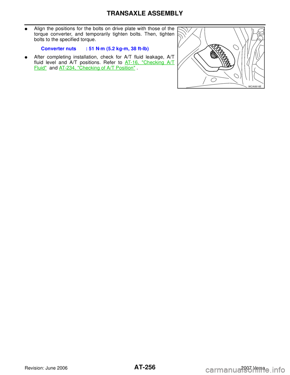
�Align the positions for the bolts on drive plate with those of the
torque converter, and temporarily tighten bolts. Then, tighten
bolts to the specified torque.
�After completing installation, check for A/T fluid leakage, A/T
fluid level and A/T positions. Refer to AT-16, "
Checking A/T
Fluid" and AT-234, "Checking of A/T Position" . Converter nuts : 51 N·m (5.2 kg-m, 38 ft-lb)
WCIA0616E
Page 310 of 2896

REPAIR FOR COMPONENT PARTS
AT-297
D
E
F
G
H
I
J
K
L
MA
B
AT
Revision: June 20062007 Versa
INSPECTION
Control Valve Lower and Upper Bodies
CAUTION:
Be careful not to lose these parts.
�Check to see that retainer plates are properly positioned in con-
trol valve lower body.
�Check to see that retainer plates are properly positioned in con-
trol valve upper body.
Oil Strainer
Check wire netting of oil strainer for damage. Replace if necessary.
Shift Solenoid Valves “A” and “B”, Line Pressure Solenoid Valve, Torque Converter Clutch
Solenoid Valve and Overrun Clutch Solenoid Valve
Measure resistance.
�For shift solenoid valve A, refer to AT-155, "Component Inspec-
tion" .
�For shift solenoid valve B, refer to AT-160, "Component Inspec-
tion" .
�For line pressure solenoid valve, refer to AT-150, "Component
Inspection" .
�For torque converter clutch solenoid valve, refer to AT-138,
"Component Inspection" .
�For overrun clutch solenoid valve, refer to AT-165, "Component
Inspection" .
A/T Fluid Temperature Sensor
Measure resistance.
SCIA4978E
SCIA4979E
SCIA3291E
SCIA3485E
Page 311 of 2896
AT-298
REPAIR FOR COMPONENT PARTS
Revision: June 20062007 Versa
�For A/T fluid temperature sensor, refer to AT-175, "Component
Inspection" .
Line Pressure Relief Valve Springs and Torque Converter Pressure Holding Spring
�Check each spring for damage or deformation. Also measure
free length and outer diameter. Refer to AT-380, "
Control
Va l v e s" .
�Replace springs if deformed or fatigued.
ASSEMBLY
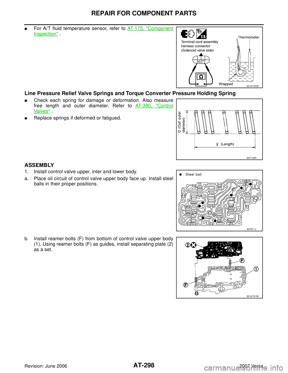
1. Install control valve upper, inter and lower body.
a. Place oil circuit of control valve upper body face up. Install steel
balls in their proper positions.
b. Install reamer bolts (F) from bottom of control valve upper body
(1). Using reamer bolts (F) as guides, install separating plate (2)
as a set.
SCIA7533E
SAT1 3 8D
SAT8 7 1J
SCIA7010E
Page 322 of 2896

REPAIR FOR COMPONENT PARTS
AT-309
D
E
F
G
H
I
J
K
L
MA
B
AT
Revision: June 20062007 Versa
Reverse ClutchUCS005W 8
COMPONENTS
DISASSEMBLY
1. Check operation of reverse clutch
a. Install seal rings to drum support of oil pump assembly, and set reverse clutch assembly.
b. Apply compressed air into the oil hole at the location as shown
in the figure.
c. Check to see that retaining plate moves to snap ring.
d. If retaining plate does not contact snap ring:
�D-ring might be damaged.
�Seal lip might be damaged.
�Fluid might be leaking past piston check ball.
2. Remove snap ring (1) using a flat-bladed screwdriver A.
3. Remove retaining plate, drive plates, driven plates and dish
plates.
1. Reverse clutch drum 2. D-ring 3. Seal lip
4. Reverse clutch piston 5. Spring retainer assembly 6. Snap ring
7. Dish plate 8. Driven plate 9. Retaining plate
10. Snap ring 11. Drive plate
Refer to GI section to make sure icons (symbol marks) in the figure. Refer to GI-10, "
Components" .
SCIA6939J
SAT1 5 5D
SCIA7024J
Page 333 of 2896

AT-320
REPAIR FOR COMPONENT PARTS
Revision: June 20062007 Versa
Forward and Overrun ClutchesUCS005WA
COMPONENTS
DISASSEMBLY
1. Check operation of forward clutch.
a. Install seal rings to bearing retainer, and set forward clutch drum.
b. Apply compressed air into oil hole of bearing retainer at the loca-
tion as shown in the figure.
c. Check to see that retaining plate moves to snap ring.
d. If retaining plate does not contact snap ring:
�D-ring might be damaged.
�Seal lip might be damaged.
�Fluid might be leaking past piston check ball.
2. Check operation of overrun clutch.
a. Install seal rings to bearing retainer, and set forward clutch drum.
1. Dish plate 2. Driven plate 3. Retaining plate
4. Snap ring 5. Dish plate 6. Driven plate
7. Retaining plate 8. Snap ring 9. Forward clutch
10. Drive plate 11. Drive plate 12. Overrun clutch
13. Snap ring 14. Spring retainer assembly 15. Overrun clutch piston
16. D-ring 17. Seal lip 18. Forward clutch piston
19. D-ring 20. Seal lip 21. Forward clutch drum
Refer to Refer to Service Manual for symbol mark in the figure.
SCIA8010E
SAT2 0 1D
Page 334 of 2896

REPAIR FOR COMPONENT PARTS
AT-321
D
E
F
G
H
I
J
K
L
MA
B
AT
Revision: June 20062007 Versa
b. Apply compressed air into oil hole of bearing retainer at the loca-
tion as shown in the figure.
c. Check to see that retaining plate moves to snap ring.
d. If retaining plate does not contact snap ring:
�D-ring might be damaged.
�Seal lip might be damaged.
�Fluid might be leaking past piston check ball.
3. Remove snap ring for forward clutch from forward clutch drum
using a flat-bladed screwdriver.
4. Remove retaining plate, drive plates, driven plates and dish
plate for forward clutch.
5. Remove snap ring for overrun clutch from forward clutch drum
using a flat-bladed screwdriver.
6. Remove retaining plate, drive plates, driven plates and dish
plate for overrun clutch.
7. Set Tool A on spring retainer assembly, and remove snap ring
(1) from forward clutch drum while compressing spring retainer
assembly.
CAUTION:
�Set SST directly over return springs.
�Do not expand snap ring excessively.
8. Remove spring retainer assembly from forward clutch drum.
CAUTION:
Do not remove return springs from spring retainer.
9. Install seal rings to bearing retainer (1), and set forward clutch
drum. Then apply compressed air into the oil hole at the location
as shown in the figure to remove overrun clutch piston from for-
ward clutch piston.
CAUTION:
Do not blow air in too quickly, or overrun clutch piston and
ATF could jump out. Carefully blow air little by little while
protecting with lint-free cloth.
SAT2 0 2D
SCIA4894E
SCIA4895E
Tool number: KV31103200 (J-39186)
SCIA7989E
SCIA6004J
Page 389 of 2896
AT-376
ASSEMBLY
Revision: June 20062007 Versa
30. Install O-ring (3) to turbine revolution sensor (power train revolu-
tion sensor) (1).
31. Install turbine revolution sensor (power train revolution sensor)
(1) to transaxle case (2).
: Bolt (1)
32. Tighten turbine revolution sensor (power train revolution sensor)
fitting bolt to the specified torque. Refer to AT-257, "
Compo-
nents" .
33. Install revolution sensor (1) to transaxle case (2).
34. Tighten revolution sensor fitting bolts to the specified torque.
Refer to AT-257, "
Components" .
: Bolt (2)
CAUTION:
Ensure revolution sensor harness is firmly secured with
bolt.
(1): Revolution sensor
: Bolt (1)
35. Install torque converter.
a. Pour ATF into torque converter.
�Approximately 1 liter (1 US qt, 7/8 Imp pt) of fluid is
required for a new torque converter.
�When reusing old torque converter, add the same amount
of ATF as was drained.
SCIA7004J
SCIA7170J
SCIA6518J
SAT4 2 8DA
 to turbine revolution sensor (power train revolu-
tion sensor) (1).
31. Install turbine revolution sensor (power train revolution s")