2007 NISSAN LATIO seat adjustment
[x] Cancel search: seat adjustmentPage 82 of 2896
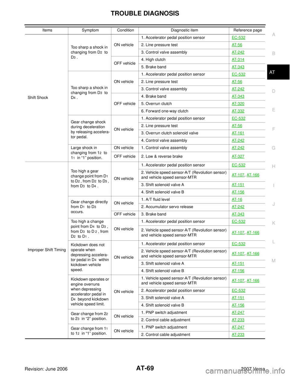
TROUBLE DIAGNOSIS
AT-69
D
E
F
G
H
I
J
K
L
MA
B
AT
Revision: June 20062007 Versa
Shift ShockToo sharp a shock in
changing from D
2 to
D
3 .ON vehicle1. Accelerator pedal position sensorEC-532
2. Line pressure testAT- 5 6
3. Control valve assemblyAT- 2 4 2
OFF vehicle4. High clutchAT- 3 1 45. Brake bandAT- 3 4 3
Too sharp a shock in
changing from D
3 to
D
4 .ON vehicle1. Accelerator pedal position sensorEC-532
2. Line pressure testAT- 5 6
3. Control valve assemblyAT- 2 4 2
OFF vehicle4. Brake bandAT- 3 4 35. Overrun clutchAT- 3 2 0
6. Forward one-way clutchAT- 3 3 2
Gear change shock
during deceleration
by releasing accelera-
tor pedal.ON vehicle1. Accelerator pedal position sensorEC-5322. Line pressure testAT- 5 6
3. Overrun clutch solenoid valveAT- 1 6 1
4. Control valve assemblyAT- 2 4 2
Large shock in
changing from 1
2 to
1
1 in “1” position.ON vehicle 1. Control valve assemblyAT- 2 4 2OFF vehicle 2. Low & reverse brakeAT- 3 2 7
Improper Shift TimingToo high a gear
change point from D
1
to D
2 , from D2 t o D3 ,
from D
3 to D4 .ON vehicle1. Accelerator pedal position sensorEC-532
2. Vehicle speed sensor·A/T (Revolution sensor)
and vehicle speed sensor·MTRAT- 1 0 7, AT- 1 6 6
3. Shift solenoid valve AAT- 1 5 1
4. Shift solenoid valve BAT- 1 5 6
Gear change directly
from D
1 to D3
occurs.ON vehicle1. A/T fluid levelAT- 1 62. Accumulator servo releaseAT- 2 4 2
OFF vehicle 3. Brake bandAT- 3 4 3
Too high a change
point from D
4 to D3 ,
from D
3 to D 2 , from
D
2 to D1 .ON vehicle1. Accelerator pedal position sensorEC-532
2. Vehicle speed sensor·A/T (Revolution sensor)
and vehicle speed sensor·MTRAT- 1 0 7, AT- 1 6 6
Kickdown does not
operate when
depressing accelera-
tor pedal in D
4 within
kickdown vehicle
speed.ON vehicle1. Accelerator pedal position sensorEC-532
2. Vehicle speed sensor·A/T (Revolution sensor)
and vehicle speed sensor·MTRAT- 1 0 7, AT- 1 6 6
3. Shift solenoid valve AAT- 1 5 1
4. Shift solenoid valve BAT- 1 5 6
Kickdown operates or
engine overruns
when depressing
accelerator pedal in
D
4 beyond kickdown
vehicle speed limit.ON vehicle1. Vehicle speed sensor·A/T (Revolution sensor)
and vehicle speed sensor·MTRAT- 1 0 7
, AT- 1 6 6
2. Accelerator pedal position sensorEC-532
3. Shift solenoid valve AAT- 1 5 1
4. Shift solenoid valve BAT- 1 5 6
Gear change from 22
to 2
3 in “2” position.ON vehicle1. PNP switch adjustmentAT- 2 4 72. Control cable adjustmentAT- 2 3 3
Gear change from 11
to 1
2 in “1” position.ON vehicle1. PNP switch adjustmentAT- 2 4 72. Control cable adjustmentAT- 2 3 3
Items Symptom Condition Diagnostic item Reference page
Page 490 of 2896
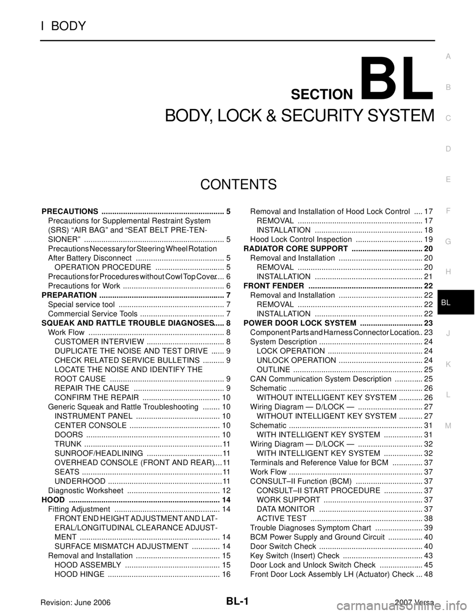
BL-1
BODY, LOCK & SECURITY SYSTEM
I BODY
CONTENTS
C
D
E
F
G
H
J
K
L
M
SECTION BL
A
B
BL
Revision: June 20062007 Versa PRECAUTIONS .......................................................... 5
Precautions for Supplemental Restraint System
(SRS) “AIR BAG” and “SEAT BELT PRE-TEN-
SIONER” .................................................................. 5
Precautions Necessary for Steering Wheel Rotation
After Battery Disconnect .......................................... 5
OPERATION PROCEDURE ................................. 5
Precautions for Procedures without Cowl Top Cover ..... 6
Precautions for Work ................................................ 6
PREPARATION ........................................................... 7
Special service tool .................................................. 7
Commercial Service Tools ........................................ 7
SQUEAK AND RATTLE TROUBLE DIAGNOSES ..... 8
Work Flow ................................................................ 8
CUSTOMER INTERVIEW ..................................... 8
DUPLICATE THE NOISE AND TEST DRIVE ....... 9
CHECK RELATED SERVICE BULLETINS ........... 9
LOCATE THE NOISE AND IDENTIFY THE
ROOT CAUSE ...................................................... 9
REPAIR THE CAUSE ........................................... 9
CONFIRM THE REPAIR ..................................... 10
Generic Squeak and Rattle Troubleshooting ......... 10
INSTRUMENT PANEL ........................................ 10
CENTER CONSOLE ........................................... 10
DOORS ............................................................... 10
TRUNK .................................................................11
SUNROOF/HEADLINING ....................................11
OVERHEAD CONSOLE (FRONT AND REAR) ....11
SEATS ..................................................................11
UNDERHOOD ......................................................11
Diagnostic Worksheet ............................................ 12
HOOD ....................................................................... 14
Fitting Adjustment .................................................. 14
FRONT END HEIGHT ADJUSTMENT AND LAT-
ERAL/LONGITUDINAL CLEARANCE ADJUST-
MENT .................................................................. 14
SURFACE MISMATCH ADJUSTMENT .............. 14
Removal and Installation ........................................ 15
HOOD ASSEMBLY ............................................. 15
HOOD HINGE ..................................................... 16Removal and Installation of Hood Lock Control ..... 17
REMOVAL ........................................................... 17
INSTALLATION ................................................... 18
Hood Lock Control Inspection ................................ 19
RADIATOR CORE SUPPORT .................................. 20
Removal and Installation ........................................ 20
REMOVAL ........................................................... 20
INSTALLATION ................................................... 21
FRONT FENDER ...................................................... 22
Removal and Installation ........................................ 22
REMOVAL ........................................................... 22
INSTALLATION ................................................... 22
POWER DOOR LOCK SYSTEM .............................. 23
Component Parts and Harness Connector Location ... 23
System Description ................................................. 24
LOCK OPERATION ............................................. 24
UNLOCK OPERATION ........................................ 24
OUTLINE ............................................................. 25
CAN Communication System Description .............. 25
Schematic ............................................................... 26
WITHOUT INTELLIGENT KEY SYSTEM ............ 26
Wiring Diagram — D/LOCK — ............................... 27
WITHOUT INTELLIGENT KEY SYSTEM ............ 27
Schematic ............................................................... 31
WITH INTELLIGENT KEY SYSTEM ................... 31
Wiring Diagram — D/LOCK — ............................... 32
WITH INTELLIGENT KEY SYSTEM ................... 32
Terminals and Reference Value for BCM ............... 37
Work Flow ............................................................... 37
CONSULT–II Function (BCM) ................................ 37
CONSULT–II START PROCEDURE ................... 37
WORK SUPPORT ............................................... 37
DATA MONITOR ................................................. 37
ACTIVE TEST ..................................................... 38
Trouble Diagnoses Symptom Chart ....................... 39
BCM Power Supply and Ground Circuit ................. 40
Door Switch Check ................................................. 40
Key Switch (Insert) Check ...................................... 43
Door Lock and Unlock Switch Check ..................... 45
Front Door Lock Assembly LH (Actuator) Check .... 48
Page 500 of 2896

SQUEAK AND RATTLE TROUBLE DIAGNOSES
BL-11
C
D
E
F
G
H
J
K
L
MA
B
BL
Revision: June 20062007 Versa
TRUNK
Trunk noises are often caused by a loose jack or loose items put into the trunk by the owner.
In addition look for:
1. Trunk lid bumpers out of adjustment
2. Trunk lid striker out of adjustment
3. The trunk lid torsion bars knocking together
4. A loose license plate or bracket
Most of these incidents can be repaired by adjusting, securing or insulating the item(s) or component(s) caus-
ing the noise.
SUNROOF/HEADLINING
Noises in the sunroof/headlining area can often be traced to one of the following:
1. Sunroof lid, rail, linkage or seals making a rattle or light knocking noise
2. Sun visor shaft shaking in the holder
3. Front or rear windshield touching headliner and squeaking
Again, pressing on the components to stop the noise while duplicating the conditions can isolate most of these
incidents. Repairs usually consist of insulating with felt cloth tape.
OVERHEAD CONSOLE (FRONT AND REAR)
Overhead console noises are often caused by the console panel clips not being engaged correctly. Most of
these incidents are repaired by pushing up on the console at the clip locations until the clips engage.
In addition look for:
1. Loose harness or harness connectors.
2. Front console map/reading lamp lense loose.
3. Loose screws at console attachment points.
SEATS
When isolating seat noise it's important to note the position the seat is in and the load placed on the seat when
the noise is present. These conditions should be duplicated when verifying and isolating the cause of the
noise.
Cause of seat noise include:
1. Headrest rods and holder
2. A squeak between the seat pad cushion and frame
3. The rear seatback lock and bracket
These noises can be isolated by moving or pressing on the suspected components while duplicating the con-
ditions under which the noise occurs. Most of these incidents can be repaired by repositioning the component
or applying urethane tape to the contact area.
UNDERHOOD
Some interior noise may be caused by components under the hood or on the engine wall. The noise is then
transmitted into the passenger compartment.
Causes of transmitted underhood noise include:
1. Any component mounted to the engine wall
2. Components that pass through the engine wall
3. Engine wall mounts and connectors
4. Loose radiator mounting pins
5. Hood bumpers out of adjustment
6. Hood striker out of adjustment
These noises can be difficult to isolate since they cannot be reached from the interior of the vehicle. The best
method is to secure, move or insulate one component at a time and test drive the vehicle. Also, engine RPM
or load can be changed to isolate the noise. Repairs can usually be made by moving, adjusting, securing, or
insulating the component causing the noise.
Page 784 of 2896
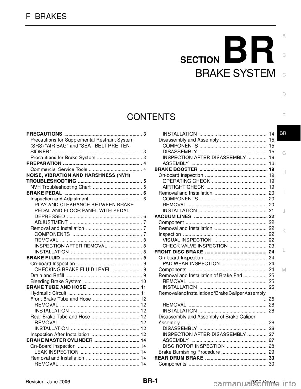
BR-1
BRAKE SYSTEM
F BRAKES
CONTENTS
C
D
E
G
H
I
J
K
L
M
SECTION BR
A
B
BR
Revision: June 20062007 Versa PRECAUTIONS .......................................................... 3
Precautions for Supplemental Restraint System
(SRS) “AIR BAG” and “SEAT BELT PRE-TEN-
SIONER” .................................................................. 3
Precautions for Brake System .................................. 3
PREPARATION ........................................................... 4
Commercial Service Tools ........................................ 4
NOISE, VIBRATION AND HARSHNESS (NVH)
TROUBLESHOOTING ................................................ 5
NVH Troubleshooting Chart ..................................... 5
BRAKE PEDAL .......................................................... 6
Inspection and Adjustment ....................................... 6
PLAY AND CLEARANCE BETWEEN BRAKE
PEDAL AND FLOOR PANEL WITH PEDAL
DEPRESSED ........................................................ 6
ADJUSTMENT ...................................................... 7
Removal and Installation .......................................... 7
COMPONENTS .................................................... 7
REMOVAL ............................................................. 8
INSPECTION AFTER REMOVAL ......................... 8
INSTALLATION ..................................................... 8
BRAKE FLUID ............................................................ 9
On-board Inspection ................................................. 9
CHECKING BRAKE FLUID LEVEL ...................... 9
Drain and Refill ......................................................... 9
Bleeding Brake System .......................................... 10
BRAKE TUBE AND HOSE ........................................11
Hydraulic Circuit ......................................................11
Front Brake Tube and Hose ................................... 12
REMOVAL ........................................................... 12
INSTALLATION ................................................... 12
Rear Brake Tube and Hose .................................... 12
REMOVAL ........................................................... 12
INSTALLATION ................................................... 12
Inspection After Installation .................................... 12
BRAKE MASTER CYLINDER .................................. 14
On-Board Inspection .............................................. 14
LEAK INSPECTION ............................................ 14
Removal and Installation ........................................ 14
REMOVAL ........................................................... 14INSTALLATION ................................................... 14
Disassembly and Assembly .................................... 15
COMPONENTS ................................................... 15
DISASSEMBLY ................................................... 15
INSPECTION AFTER DISASSEMBLY ................ 16
ASSEMBLY ......................................................... 16
BRAKE BOOSTER ................................................... 19
On-board Inspection ............................................... 19
OPERATING CHECK .......................................... 19
AIRTIGHT CHECK .............................................. 19
Removal and Installation ........................................ 20
COMPONENTS ................................................... 20
REMOVAL ........................................................... 20
INSTALLATION ................................................... 21
VACUUM LINES ....................................................... 22
Component ............................................................. 22
Removal and Installation ........................................ 22
Inspection ............................................................... 22
VISUAL INSPECTION ......................................... 22
CHECK VALVE INSPECTION ............................. 23
FRONT DISC BRAKE ............................................... 24
On-board Inspection ............................................... 24
PAD WEAR INSPECTION ................................... 24
Components ........................................................... 24
Removal and Installation of Brake Pad .................. 25
REMOVAL ........................................................... 25
INSTALLATION ................................................... 25
Removal and Installation of Brake Caliper Assembly
... 26
REMOVAL ........................................................... 26
INSTALLATION ................................................... 26
Disassembly and Assembly of Brake Caliper
Assembly ................................................................ 26
DISASSEMBLY ................................................... 26
INSPECTION AFTER DISASSEMBLY ................ 27
ASSEMBLY ......................................................... 27
DISC ROTOR INSPECTION ............................... 28
Brake Burnishing Procedure ................................... 29
REAR DRUM BRAKE ............................................... 30
Components ........................................................... 30
Page 858 of 2896
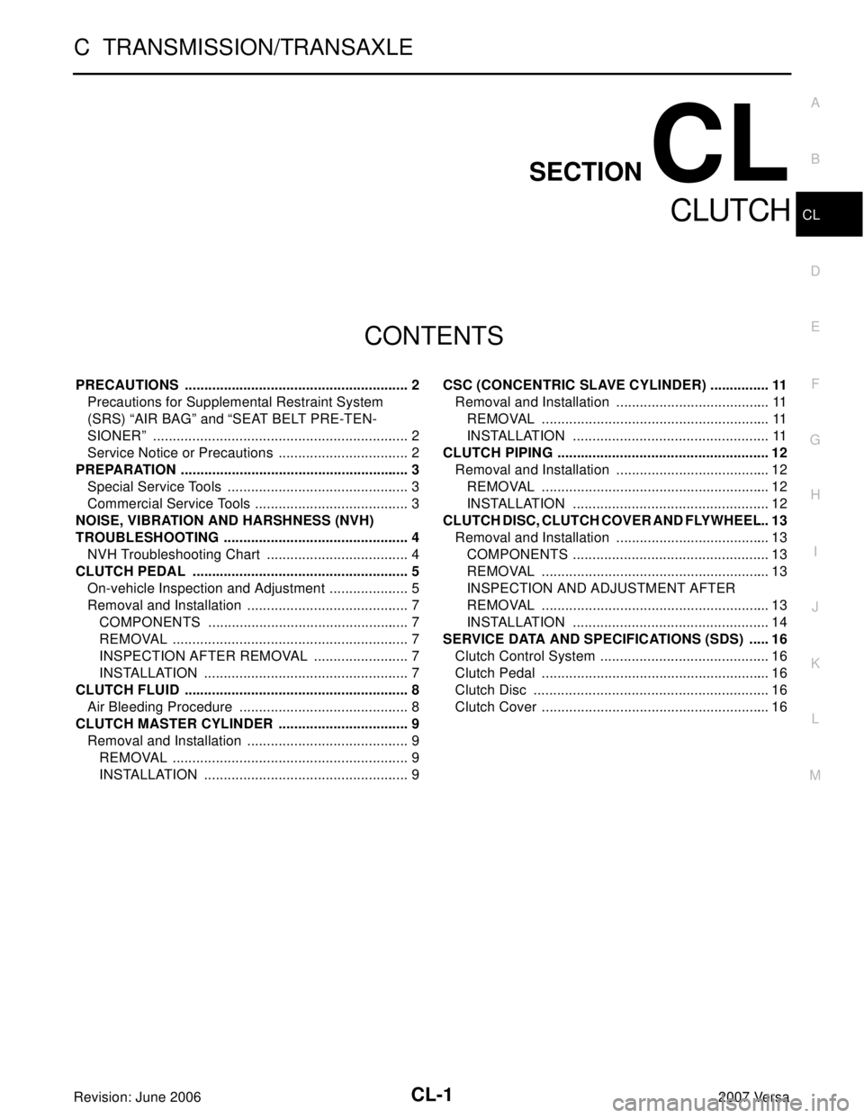
CL-1
CLUTCH
C TRANSMISSION/TRANSAXLE
CONTENTS
D
E
F
G
H
I
J
K
L
M
SECTION CL
A
B
CL
Revision: June 20062007 Versa PRECAUTIONS .......................................................... 2
Precautions for Supplemental Restraint System
(SRS) “AIR BAG” and “SEAT BELT PRE-TEN-
SIONER” .................................................................. 2
Service Notice or Precautions .................................. 2
PREPARATION ........................................................... 3
Special Service Tools ............................................... 3
Commercial Service Tools ........................................ 3
NOISE, VIBRATION AND HARSHNESS (NVH)
TROUBLESHOOTING ................................................ 4
NVH Troubleshooting Chart ..................................... 4
CLUTCH PEDAL ........................................................ 5
On-vehicle Inspection and Adjustment ..................... 5
Removal and Installation .......................................... 7
COMPONENTS .................................................... 7
REMOVAL ............................................................. 7
INSPECTION AFTER REMOVAL ......................... 7
INSTALLATION ..................................................... 7
CLUTCH FLUID .......................................................... 8
Air Bleeding Procedure ............................................ 8
CLUTCH MASTER CYLINDER .................................. 9
Removal and Installation .......................................... 9
REMOVAL ............................................................. 9
INSTALLATION ..................................................... 9CSC (CONCENTRIC SLAVE CYLINDER) ................ 11
Removal and Installation ........................................ 11
REMOVAL ........................................................... 11
INSTALLATION ................................................... 11
CLUTCH PIPING ....................................................... 12
Removal and Installation ........................................ 12
REMOVAL ........................................................... 12
INSTALLATION ................................................... 12
CLUTCH DISC, CLUTCH COVER AND FLYWHEEL ... 13
Removal and Installation ........................................ 13
COMPONENTS ................................................... 13
REMOVAL ........................................................... 13
INSPECTION AND ADJUSTMENT AFTER
REMOVAL ........................................................... 13
INSTALLATION ................................................... 14
SERVICE DATA AND SPECIFICATIONS (SDS) ...... 16
Clutch Control System ............................................ 16
Clutch Pedal ........................................................... 16
Clutch Disc ............................................................. 16
Clutch Cover ........................................................... 16
Page 1161 of 2896
DI-52
WARNING CHIME
Revision: June 20062007 Versa
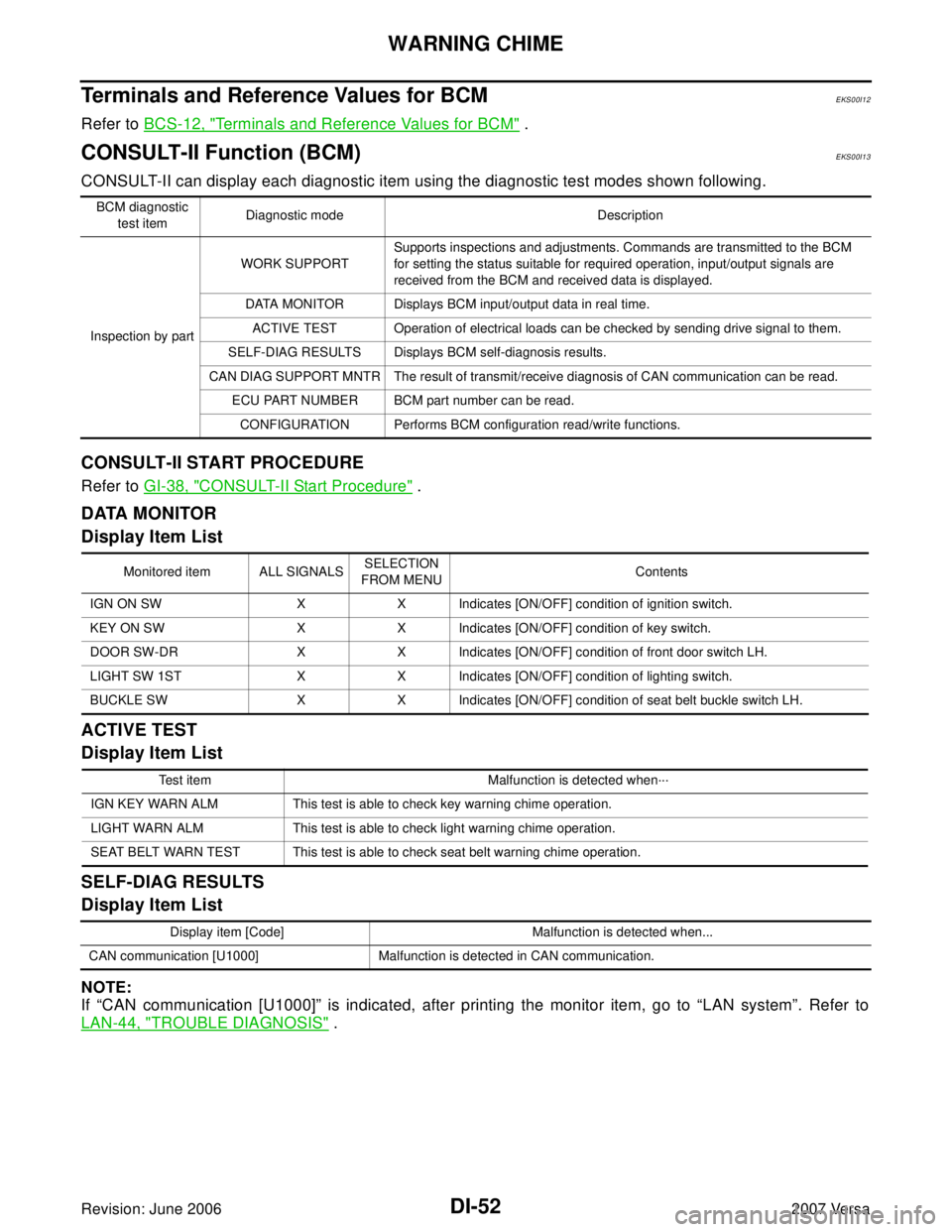
Terminals and Reference Values for BCMEKS00I12
Refer to BCS-12, "Terminals and Reference Values for BCM" .
CONSULT-II Function (BCM)EKS00I13
CONSULT-II can display each diagnostic item using the diagnostic test modes shown following.
CONSULT-II START PROCEDURE
Refer to GI-38, "CONSULT-II Start Procedure" .
DATA MONITOR
Display Item List
ACTIVE TEST
Display Item List
SELF-DIAG RESULTS
Display Item List
NOTE:
If “CAN communication [U1000]” is indicated, after printing the monitor item, go to “LAN system”. Refer to
LAN-44, "
TROUBLE DIAGNOSIS" .
BCM diagnostic
test itemDiagnostic mode Description
Inspection by partWORK SUPPORTSupports inspections and adjustments. Commands are transmitted to the BCM
for setting the status suitable for required operation, input/output signals are
received from the BCM and received data is displayed.
DATA MONITOR Displays BCM input/output data in real time.
ACTIVE TEST Operation of electrical loads can be checked by sending drive signal to them.
SELF-DIAG RESULTS Displays BCM self-diagnosis results.
CAN DIAG SUPPORT MNTR The result of transmit/receive diagnosis of CAN communication can be read.
ECU PART NUMBER BCM part number can be read.
CONFIGURATION Performs BCM configuration read/write functions.
Monitored item ALL SIGNALSSELECTION
FROM MENUContents
IGN ON SW X X Indicates [ON/OFF] condition of ignition switch.
KEY ON SW X X Indicates [ON/OFF] condition of key switch.
DOOR SW-DR X X Indicates [ON/OFF] condition of front door switch LH.
LIGHT SW 1ST X X Indicates [ON/OFF] condition of lighting switch.
BUCKLE SW X X Indicates [ON/OFF] condition of seat belt buckle switch LH.
Test item Malfunction is detected when···
IGN KEY WARN ALM This test is able to check key warning chime operation.
LIGHT WARN ALM This test is able to check light warning chime operation.
SEAT BELT WARN TEST This test is able to check seat belt warning chime operation.
Display item [Code] Malfunction is detected when...
CAN communication [U1000] Malfunction is detected in CAN communication.
Page 1773 of 2896

EI-8
SQUEAK AND RATTLE TROUBLE DIAGNOSIS
Revision: June 20062007 Versa
Tapping or moving the components or pressing on them while driving to duplicate the conditions can isolate
many of these incidents. You can usually insulate the areas with felt cloth tape or insulator foam blocks from
the NISSAN Squeak and Rattle Kit (J-43980) to repair the noise.
TRUNK
Trunk noises are often caused by a loose jack or loose items put into the trunk by the owner.
In addition look for:
1. Trunk lid bumpers out of adjustment
2. Trunk lid striker out of adjustment
3. The trunk lid torsion bars knocking together
4. A loose license plate or bracket
Most of these incidents can be repaired by adjusting, securing or insulating the item(s) or component(s) caus-
ing the noise.
SUNROOF/HEADLINING
Noises in the sunroof/headlining area can often be traced to one of the following:
1. Sunroof lid, rail, linkage or seals making a rattle or light knocking noise
2. Sun visor shaft shaking in the holder
3. Front or rear windshield touching headliner and squeaking
Again, pressing on the components to stop the noise while duplicating the conditions can isolate most of these
incidents. Repairs usually consist of insulating with felt cloth tape.
OVERHEAD CONSOLE (FRONT AND REAR)
Overhead console noises are often caused by the console panel clips not being engaged correctly. Most of
these incidents are repaired by pushing up on the console at the clip locations until the clips engage.
In addition look for:
1. Loose harness or harness connectors.
2. Front console map/reading lamp lens loose.
3. Loose screws at console attachment points.
SEATS
When isolating seat noise it's important to note the position the seat is in and the load placed on the seat when
the noise is present. These conditions should be duplicated when verifying and isolating the cause of the
noise.
Cause of seat noise include:
1. Headrest rods and holder
2. A squeak between the seat pad cushion and frame
3. The rear seatback lock and bracket
These noises can be isolated by moving or pressing on the suspected components while duplicating the con-
ditions under which the noise occurs. Most of these incidents can be repaired by repositioning the component
or applying urethane tape to the contact area.
UNDERHOOD
Some interior noise may be caused by components under the hood or on the engine wall. The noise is then
transmitted into the passenger compartment.
Causes of transmitted underhood noise include:
1. Any component installed on the engine wall
2. Components that pass through the engine wall
3. Engine wall mounts and connectors
4. Loose radiator pins
5. Hood bumpers out of adjustment
6. Hood striker out of adjustment
These noises can be difficult to isolate since they cannot be reached from the interior of the vehicle. The best
method is to secure, move or insulate one component at a time and test drive the vehicle. Also, engine RPM
or load can be changed to isolate the noise. Repairs can usually be made by moving, adjusting, securing, or
insulating the component causing the noise.
Page 1810 of 2896
EM-1
ENGINE MECHANICAL
B ENGINE
CONTENTS
C
D
E
F
G
H
I
J
K
L
M
SECTION EM
A
EM
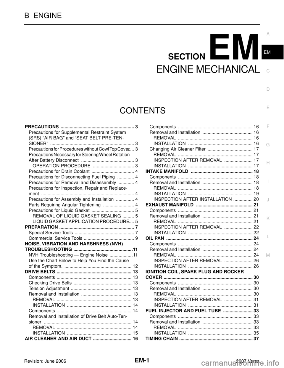
Revision: June 20062007 Versa PRECAUTIONS .......................................................... 3
Precautions for Supplemental Restraint System
(SRS) “AIR BAG” and “SEAT BELT PRE-TEN-
SIONER” .................................................................. 3
Precautions for Procedures without Cowl Top Cover ..... 3
Precautions Necessary for Steering Wheel Rotation
After Battery Disconnect .......................................... 3
OPERATION PROCEDURE ................................. 3
Precautions for Drain Coolant .................................. 4
Precautions for Disconnecting Fuel Piping .............. 4
Precautions for Removal and Disassembly ............. 4
Precautions for Inspection, Repair and Replace-
ment ......................................................................... 4
Precautions for Assembly and Installation ............... 4
Parts Requiring Angular Tightening ......................... 4
Precautions for Liquid Gasket .................................. 5
REMOVAL OF LIQUID GASKET SEALING .......... 5
LIQUID GASKET APPLICATION PROCEDURE ..... 5
PREPARATION ........................................................... 7
Special Service Tools ............................................... 7
Commercial Service Tools ........................................ 9
NOISE, VIBRATION AND HARSHNESS (NVH)
TROUBLESHOOTING ...............................................11
NVH Troubleshooting — Engine Noise ...................11
Use the Chart Below to Help You Find the Cause
of the Symptom. ..................................................... 12
DRIVE BELTS ........................................................... 13
Components ........................................................... 13
Checking Drive Belts .............................................. 13
Tension Adjustment ................................................ 13
Removal and Installation ........................................ 13
REMOVAL ........................................................... 13
INSTALLATION ................................................... 14
Components ........................................................... 14
Removal and Installation of Drive Belt Auto-Ten-
sioner ..................................................................... 14
REMOVAL ........................................................... 14
INSTALLATION ................................................... 15
AIR CLEANER AND AIR DUCT ............................... 16Components ........................................................... 16
Removal and Installation ........................................ 16
REMOVAL ........................................................... 16
INSTALLATION ................................................... 16
Changing Air Cleaner Filter .................................... 17
REMOVAL ........................................................... 17
INSPECTION AFTER REMOVAL ....................... 17
INSTALLATION ................................................... 17
INTAKE MANIFOLD ................................................. 18
Components ........................................................... 18
Removal and Installation ........................................ 18
REMOVAL ........................................................... 18
INSTALLATION ................................................... 19
INSPECTION AFTER INSTALLATION ................ 20
EXHAUST MANIFOLD ............................................. 21
Components ........................................................... 21
Removal and Installation ........................................ 21
REMOVAL ........................................................... 21
INSPECTION AFTER REMOVAL ....................... 22
INSTALLATION ................................................... 22
OIL PAN .................................................................... 24
Components ........................................................... 24
Removal and Installation ........................................ 24
REMOVAL ........................................................... 24
INSPECTION AFTER REMOVAL ....................... 26
INSTALLATION ................................................... 26
IGNITION COIL, SPARK PLUG AND ROCKER
COVER ...................................................................... 30
Components ........................................................... 30
Removal and Installation ........................................ 30
REMOVAL ........................................................... 30
INSPECTION AFTER REMOVAL ....................... 31
INSTALLATION ................................................... 31
FUEL INJECTOR AND FUEL TUBE ........................ 33
Components ........................................................... 33
Removal and Installation ........................................ 33
REMOVAL ........................................................... 33
INSTALLATION ................................................... 35
TIMING CHAIN .......................................................... 37