Page 1863 of 2896

EM-54Revision: June 2006
CAMSHAFT
2007 Versa
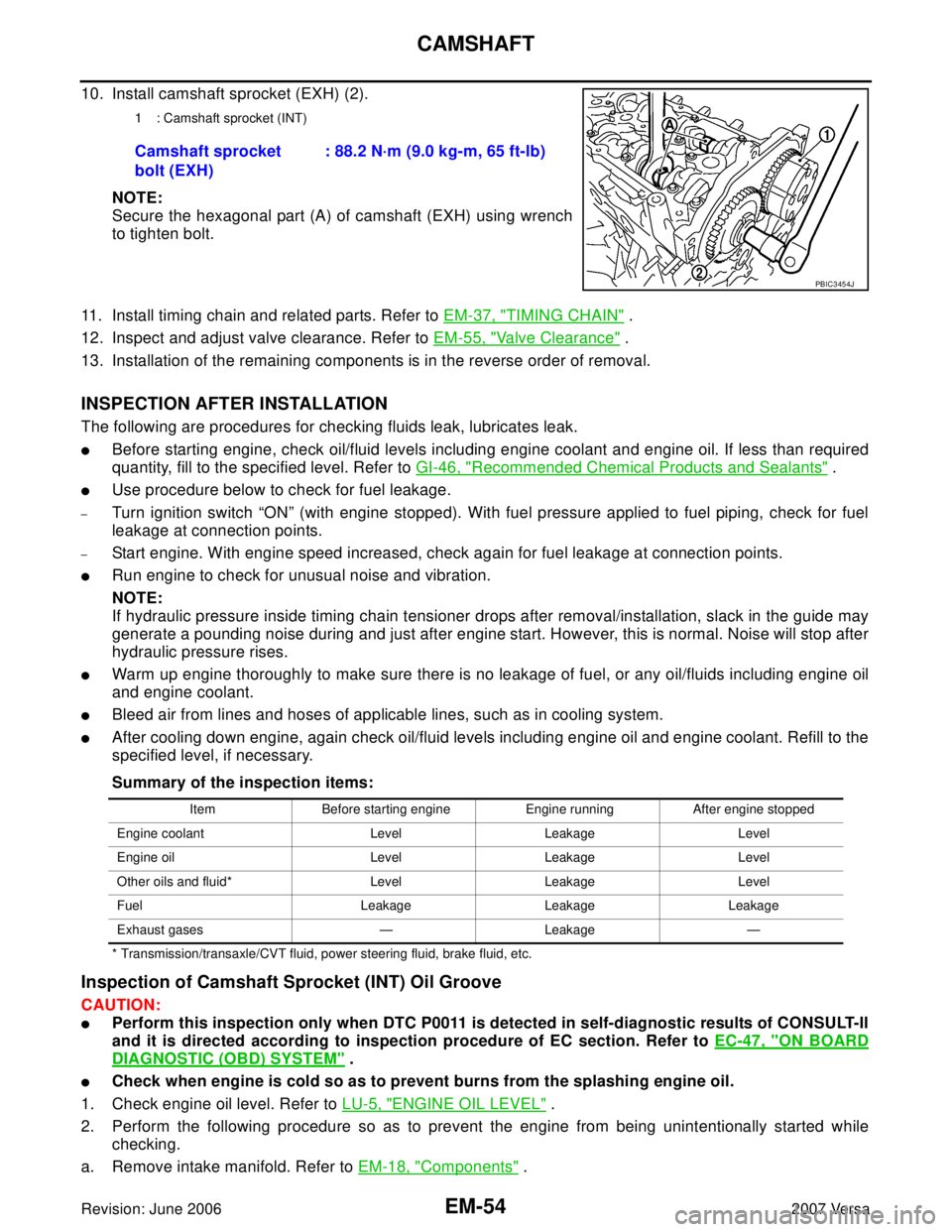
10. Install camshaft sprocket (EXH) (2).
NOTE:
Secure the hexagonal part (A) of camshaft (EXH) using wrench
to tighten bolt.
11. Install timing chain and related parts. Refer to EM-37, "
TIMING CHAIN" .
12. Inspect and adjust valve clearance. Refer to EM-55, "
Valve Clearance" .
13. Installation of the remaining components is in the reverse order of removal.
INSPECTION AFTER INSTALLATION
The following are procedures for checking fluids leak, lubricates leak.
�Before starting engine, check oil/fluid levels including engine coolant and engine oil. If less than required
quantity, fill to the specified level. Refer to GI-46, "
Recommended Chemical Products and Sealants" .
�Use procedure below to check for fuel leakage.
–Turn ignition switch “ON” (with engine stopped). With fuel pressure applied to fuel piping, check for fuel
leakage at connection points.
–Start engine. With engine speed increased, check again for fuel leakage at connection points.
�Run engine to check for unusual noise and vibration.
NOTE:
If hydraulic pressure inside timing chain tensioner drops after removal/installation, slack in the guide may
generate a pounding noise during and just after engine start. However, this is normal. Noise will stop after
hydraulic pressure rises.
�Warm up engine thoroughly to make sure there is no leakage of fuel, or any oil/fluids including engine oil
and engine coolant.
�Bleed air from lines and hoses of applicable lines, such as in cooling system.
�After cooling down engine, again check oil/fluid levels including engine oil and engine coolant. Refill to the
specified level, if necessary.
Summary of the inspection items:
* Transmission/transaxle/CVT fluid, power steering fluid, brake fluid, etc.
Inspection of Camshaft Sprocket (INT) Oil Groove
CAUTION:
�Perform this inspection only when DTC P0011 is detected in self-diagnostic results of CONSULT-II
and it is directed according to inspection procedure of EC section. Refer to EC-47, "
ON BOARD
DIAGNOSTIC (OBD) SYSTEM" .
�Check when engine is cold so as to prevent burns from the splashing engine oil.
1. Check engine oil level. Refer to LU-5, "
ENGINE OIL LEVEL" .
2. Perform the following procedure so as to prevent the engine from being unintentionally started while
checking.
a. Remove intake manifold. Refer to EM-18, "
Components" .
1 : Camshaft sprocket (INT)
Camshaft sprocket
bolt (EXH): 88.2 N·m (9.0 kg-m, 65 ft-lb)
PBIC3454J
Item Before starting engine Engine running After engine stopped
Engine coolant Level Leakage Level
Engine oil Level Leakage Level
Other oils and fluid* Level Leakage Level
Fuel Leakage Leakage Leakage
Exhaust gases — Leakage —
Page 1885 of 2896

EM-76Revision: June 2006
ENGINE ASSEMBLY
2007 Versa
INSTALLATION
Note the following, and install in the reverse order of removal.
�Do not allow engine oil to get on engine mounting insulator. Be careful not to damage engine mounting
insulator.
�When installation directions are specified, install parts according to the directions. Refer to EM-73, "Com-
ponents" .
�Make sure that each mounting insulator is seated properly, and tighten nuts and bolts.
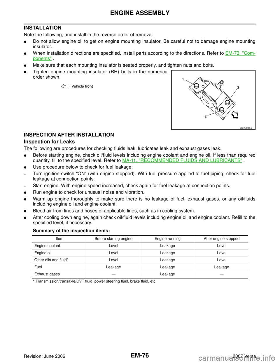
�Tighten engine mounting insulator (RH) bolts in the numerical
order shown.
INSPECTION AFTER INSTALLATION
Inspection for Leaks
The following are procedures for checking fluids leak, lubricates leak and exhaust gases leak.
�Before starting engine, check oil/fluid levels including engine coolant and engine oil. If less than required
quantity, fill to the specified level. Refer to MA-11, "
RECOMMENDED FLUIDS AND LUBRICANTS" .
�Use procedure below to check for fuel leakage.
–Turn ignition switch “ON” (with engine stopped). With fuel pressure applied to fuel piping, check for fuel
leakage at connection points.
–Start engine. With engine speed increased, check again for fuel leakage at connection points.
�Run engine to check for unusual noise and vibration.
�Warm up engine thoroughly to make sure there is no leakage of fuel, exhaust gases, or any oil/fluids
including engine oil and engine coolant.
�Bleed air from lines and hoses of applicable lines, such as in cooling system.
�After cooling down engine, again check oil/fluid levels including engine oil and engine coolant. Refill to the
specified level, if necessary.
Summary of the inspection items:
* Transmission/transaxle/CVT fluid, power steering fluid, brake fluid, etc.: Vehicle front
WBIA0785E
Item Before starting engine Engine running After engine stopped
Engine coolant Level Leakage Level
Engine oil Level Leakage Level
Other oils and fluid* Level Leakage Level
Fuel Leakage Leakage Leakage
Exhaust gases — Leakage —
Page 1994 of 2896
HOW TO USE THIS MANUAL
GI-23
C
D
E
F
G
H
I
J
K
L
MB
GI
Revision: June 20062007 Versa
AbbreviationsEAS0021P
The following ABBREVIATIONS are used:
ABBREVIATION DESCRIPTION
A/C Air Conditioner
A/T Automatic Transaxle/Transmission
ATF Automatic Transmission Fluid
CVT Continuously Variable Transmission
D
1Drive range 1st gear
D
2Drive range 2nd gear
D
3Drive range 3rd gear
D
4Drive range 4th gear
FR, RR Front, Rear
LH, RH Left-Hand, Right-Hand
M/T Manual Transaxle/Transmission
OD Overdrive
P/S Power Steering
SAE Society of Automotive Engineers, Inc.
SDS Service Data and Specifications
SST Special Service Tools
2WD 2-Wheel Drive
2
22nd range 2nd gear
2
12nd range 1st gear
1
21st range 2nd gear
1
11st range 1st gear
Page 2577 of 2896

HARNESS
PG-61
C
D
E
F
G
H
I
J
L
MA
B
PG
Revision: June 20062007 Versa
Wiring Diagram Codes (Cell Codes)EKS00IW9
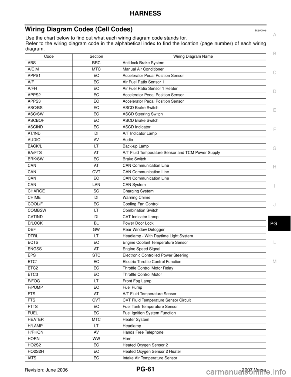
Use the chart below to find out what each wiring diagram code stands for.
Refer to the wiring diagram code in the alphabetical index to find the location (page number) of each wiring
diagram.
Code Section Wiring Diagram Name
ABS BRC Anti-lock Brake System
A/C,M MTC Manual Air Conditioner
APPS1 EC Accelerator Pedal Position Sensor
A/F EC Air Fuel Ratio Sensor 1
A/FH EC Air Fuel Ratio Sensor 1 Heater
APPS2 EC Accelerator Pedal Position Sensor
APPS3 EC Accelerator Pedal Position Sensor
ASC/BS EC ASCD Brake Switch
ASC/SW EC ASCD Steering Switch
ASCBOF EC ASCD Brake Switch
ASCIND EC ASCD Indicator
AT/IND DI A/T Indicator Lamp
AUDIO AV Audio
BACK/L LT Back-up Lamp
BA/FTS AT A/T Fluid Temperature Sensor and TCM Power Supply
BRK/SW EC Brake Switch
CAN AT CAN Communication Line
CAN CVT CAN Communication Line
CAN EC CAN Communication Line
CAN LAN CAN System
CHARGE SC Charging System
CHIME DI Warning Chime
COOL/F EC Cooling Fan Control
COMBSW LT Combination Switch
CVTIND DI CVT Indicator Lamp
D/LOCK BL Power Door Lock
DEF GW Rear Window Defogger
DTRL LT Headlamp - With Daytime Light System
ECTS EC Engine Coolant Temperature Sensor
ENGSS AT Engine Speed Signal
EPS STC Electronic Controlled Power Steering
ETC1 EC Electric Throttle Control Function
ETC2 EC Throttle Control Motor Relay
ETC3 EC Throttle Control Motor
F/FOG LT Front Fog Lamp
F/PUMP EC Fuel Pump
FTS AT A/T Fluid Temperature Sensor
FTS CVT CVT Fluid Temperature Sensor Circuit
FTTS EC Fuel Tank Temperature Sensor
FUEL EC Fuel Ignition System Function
HEATER MTC Heater System
H/LAMP LT Headlamp
H/PHON AV Hands Free Telephone
HORN WW Horn
HO2S2 EC Heated Oxygen Sensor 2
HO2S2H EC Heated Oxygen Sensor 2 Heater
IATS EC Intake Air Temperature Sensor