Page 1076 of 2896
TROUBLE DIAGNOSIS FOR SYMPTOMS
CVT-179
D
E
F
G
H
I
J
K
L
MA
B
CVT
Revision: June 20062007 Versa
TCM terminal data are reference values, measured between each terminal and ground.
Te r m i n a lWire
colorItem Condition Data (Approx.)
5 L CAN-H — —
6 P CAN-L — —
8VBack-up lamp
relaySelector lever in “R” position. 0 V
Selector lever in other positions. Battery voltage
13 G ROM assembly — —
14 Y ROM assembly — —
15 G ROM assembly — —
31 LG K-LINE — —
42 LG Sensor ground Always 0 V
46 O Sensor power—5.0 V
—0 V
Page 1077 of 2896
CVT-180
TROUBLE DIAGNOSIS FOR SYMPTOMS
Revision: June 20062007 Versa
O/D OFF Indicator Lamp Does Not Come OnUCS00645
SYMPTOM:
O/D OFF indicator lamp does not come on for about 2 seconds when turning ignition switch ON.
DIAGNOSTIC PROCEDURE
1. CHECK CAN COMMUNICATION LINE
Perform the self-diagnosis check. Refer to CVT-60, "
SELF-DIAGNOSTIC RESULT MODE" .
Is any malfunction of the
“U1000 CAN COMM CIRCUIT” indicated in the results?
YES >> Check CAN communication line. Refer to CVT-68, "DTC U1000 CAN COMMUNICATION LINE" .
NO >> GO TO 2.
2. CHECK TCM POWER SOURCE
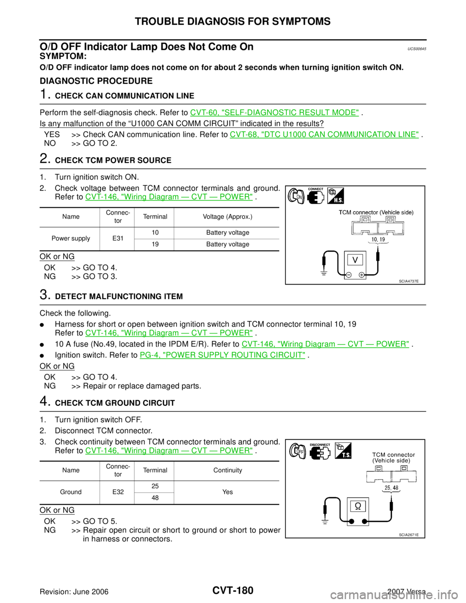
1. Turn ignition switch ON.
2. Check voltage between TCM connector terminals and ground.
Refer to CVT-146, "
Wiring Diagram — CVT — POWER" .
OK or NG
OK >> GO TO 4.
NG >> GO TO 3.
3. DETECT MALFUNCTIONING ITEM
Check the following.
�Harness for short or open between ignition switch and TCM connector terminal 10, 19
Refer to CVT-146, "
Wiring Diagram — CVT — POWER" .
�10 A fuse (No.49, located in the IPDM E/R). Refer to CVT-146, "Wiring Diagram — CVT — POWER" .
�Ignition switch. Refer to PG-4, "POWER SUPPLY ROUTING CIRCUIT" .
OK or NG
OK >> GO TO 4.
NG >> Repair or replace damaged parts.
4. CHECK TCM GROUND CIRCUIT
1. Turn ignition switch OFF.
2. Disconnect TCM connector.
3. Check continuity between TCM connector terminals and ground.
Refer to CVT-146, "
Wiring Diagram — CVT — POWER" .
OK or NG
OK >> GO TO 5.
NG >> Repair open circuit or short to ground or short to power
in harness or connectors.
NameConnec-
torTerminal Voltage (Approx.)
Power supply E3110 Battery voltage
19 Battery voltage
SCIA4737E
NameConnec-
torTerminal Continuity
Ground E3225
Ye s
48
SCIA2671E
Page 1087 of 2896
CVT-190
TRANSMISSION CONTROL MODULE
Revision: June 20062007 Versa
TRANSMISSION CONTROL MODULEPFP:31036
Removal and InstallationUCS006KZ
COMPONENTS
REMOVAL
1. Disconnect the battery negative terminal.
2. Disconnect the TCM harness connector (1) from the TCM (2).
�Instrument lower finisher (3)
3. Remove the TCM (2).
INSTALLATION
Installation is in the reverse order of removal.
1. TCM
SCIA6963E
SCIA7167E
Page 1096 of 2896
CVT SHIFT LOCK SYSTEM
CVT-199
D
E
F
G
H
I
J
K
L
MA
B
CVT
Revision: June 20062007 Versa
Diagnostic ProcedureUCS006KN
SYMPTOM 1:
�Selector lever cannot be moved from “P” position with ignition switch in ON position and brake
pedal depressed.
�Selector lever can be moved from “P” position with ignition key in ON position and brake pedal
released.
�Selector lever can be moved from “P” position when ignition switch is removed from key cylinder.
SYMPTOM 2:
�Ignition key cannot be removed when selector lever is set to “P” position.
�Ignition key can be removed when selector lever is set to any position except “P” position.
1. CHECK KEY INTERLOCK CABLE
Check key interlock cable for damage.
OK or NG
OK >> GO TO 2.
NG >> Repair key interlock cable. Refer to AT-239, "
Removal and Installation" .
2. CHECK CVT POSITION
Check CVT position. Refer to CVT-196, "
Checking of CVT Position" .
OK or NG
OK >> GO TO 3.
NG >> Adjust control cable. Refer to CVT-195, "
Adjustment of CVT Position" .
3. CHECK SHIFT LOCK SOLENOID AND PARK POSITION SWITCH
1. Turn ignition switch ON. (Do not start engine.)
2. Selector lever is set in “P” position.
3. Check operation sound.
OK or NG
OK >>INSPECTION END
NG - 1 >> With intelligent key: GO TO 4.
NG - 2 >> Without intelligent key: GO TO 5.
4. CHECK POWER SOURCE
1. Turn ignition switch ON. (Do not start engine.)
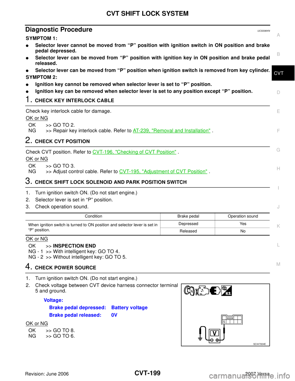
2. Check voltage between CVT device harness connector terminal
5 and ground.
OK or NG
OK >> GO TO 8.
NG >> GO TO 6.
Condition Brake pedal Operation sound
When ignition switch is turned to ON position and selector lever is set in
“P” position.Depressed Yes
Released No
Voltage:
Brake pedal depressed: Battery voltage
Brake pedal released: 0V
SCIA7934E
Page 1097 of 2896
CVT-200
CVT SHIFT LOCK SYSTEM
Revision: June 20062007 Versa
5. CHECK POWER SOURCE
1. Turn ignition switch ON. (Do not start engine.)
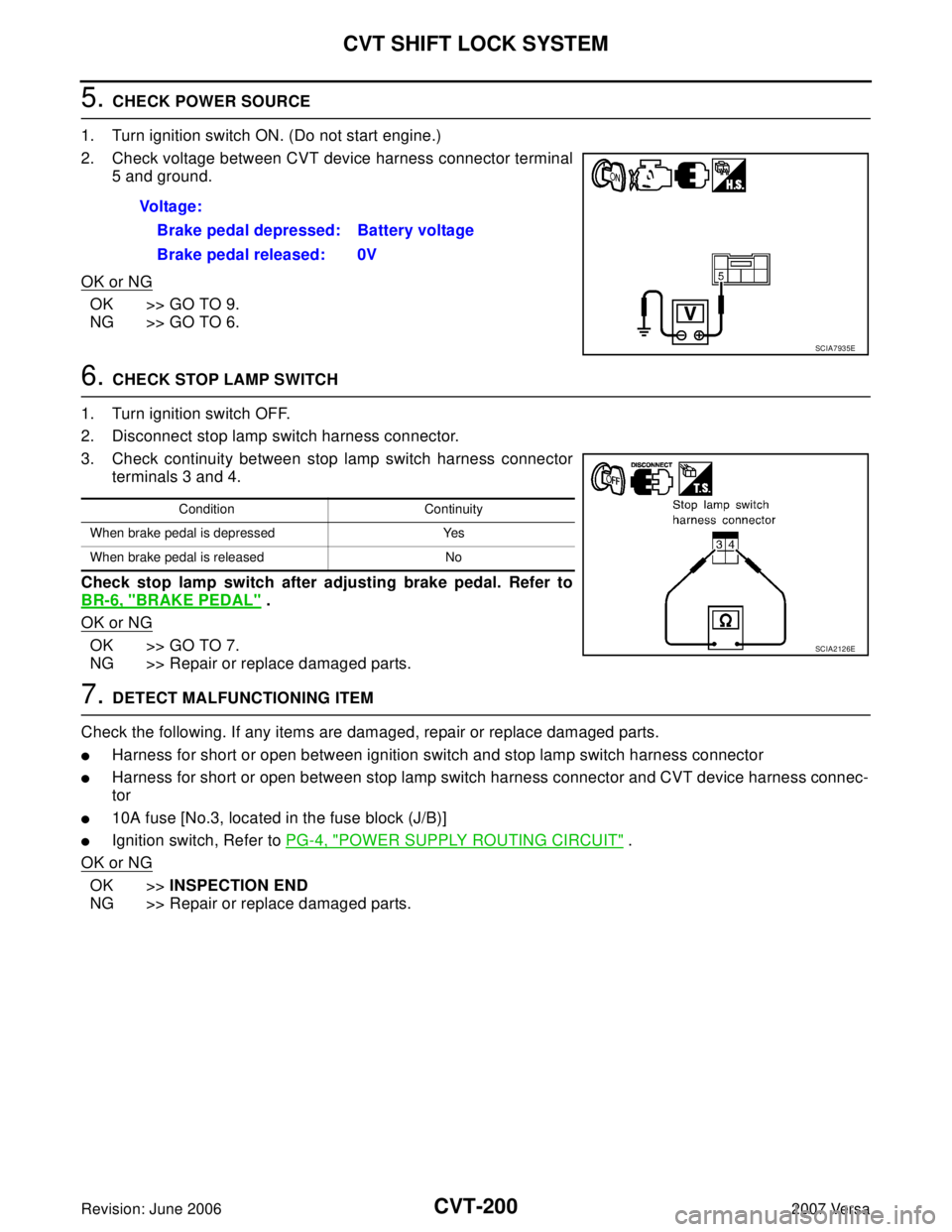
2. Check voltage between CVT device harness connector terminal
5 and ground.
OK or NG
OK >> GO TO 9.
NG >> GO TO 6.
6. CHECK STOP LAMP SWITCH
1. Turn ignition switch OFF.
2. Disconnect stop lamp switch harness connector.
3. Check continuity between stop lamp switch harness connector
terminals 3 and 4.
Check stop lamp switch after adjusting brake pedal. Refer to
BR-6, "
BRAKE PEDAL" .
OK or NG
OK >> GO TO 7.
NG >> Repair or replace damaged parts.
7. DETECT MALFUNCTIONING ITEM
Check the following. If any items are damaged, repair or replace damaged parts.
�Harness for short or open between ignition switch and stop lamp switch harness connector
�Harness for short or open between stop lamp switch harness connector and CVT device harness connec-
tor
�10A fuse [No.3, located in the fuse block (J/B)]
�Ignition switch, Refer to PG-4, "POWER SUPPLY ROUTING CIRCUIT" .
OK or NG
OK >>INSPECTION END
NG >> Repair or replace damaged parts. Voltage:
Brake pedal depressed: Battery voltage
Brake pedal released: 0V
SCIA7935E
Condition Continuity
When brake pedal is depressed Yes
When brake pedal is released No
SCIA2126E
Page 1120 of 2896
COMBINATION METERS
DI-11
C
D
E
F
G
H
I
J
L
MA
B
DI
Revision: June 20062007 Versa
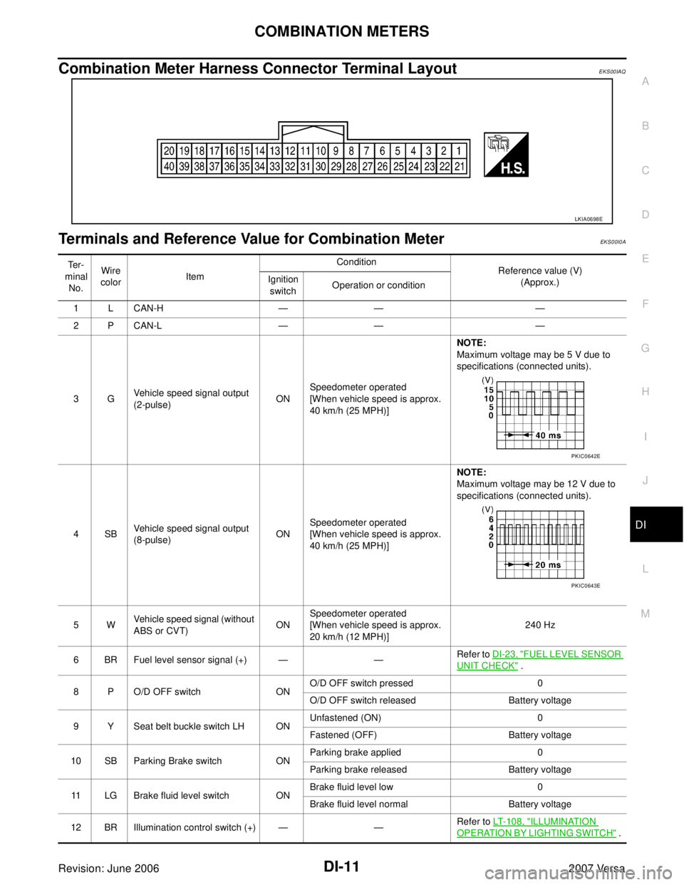
Combination Meter Harness Connector Terminal LayoutEKS00IAQ
Terminals and Reference Value for Combination MeterEKS00I0A
LKIA0698E
Te r -
minal
No.Wire
colorItemCondition
Reference value (V)
(Approx.) Ignition
switchOperation or condition
1 L CAN-H — — —
2 P CAN-L — — —
3GVehicle speed signal output
(2-pulse)ONSpeedometer operated
[When vehicle speed is approx.
40 km/h (25 MPH)] NOTE:
Maximum voltage may be 5 V due to
specifications (connected units).
4SBVehicle speed signal output
(8-pulse)ONSpeedometer operated
[When vehicle speed is approx.
40 km/h (25 MPH)]NOTE:
Maximum voltage may be 12 V due to
specifications (connected units).
5WVehicle speed signal (without
ABS or CVT)ONSpeedometer operated
[When vehicle speed is approx.
20 km/h (12 MPH)]240 Hz
6 BR Fuel level sensor signal (+) — —Refer to DI-23, "
FUEL LEVEL SENSOR
UNIT CHECK" .
8 P O/D OFF switch ONO/D OFF switch pressed 0
O/D OFF switch released Battery voltage
9 Y Seat belt buckle switch LH ONUnfastened (ON) 0
Fastened (OFF) Battery voltage
10 SB Parking Brake switch ONParking brake applied 0
Parking brake released Battery voltage
11 LG Brake fluid level switch ONBrake fluid level low 0
Brake fluid level normal Battery voltage
12 BR Illumination control switch (+) — —Refer to LT-108, "
ILLUMINATION
OPERATION BY LIGHTING SWITCH" .
PKIC0642E
PKIC0643E
Page 1121 of 2896
DI-12
COMBINATION METERS
Revision: June 20062007 Versa
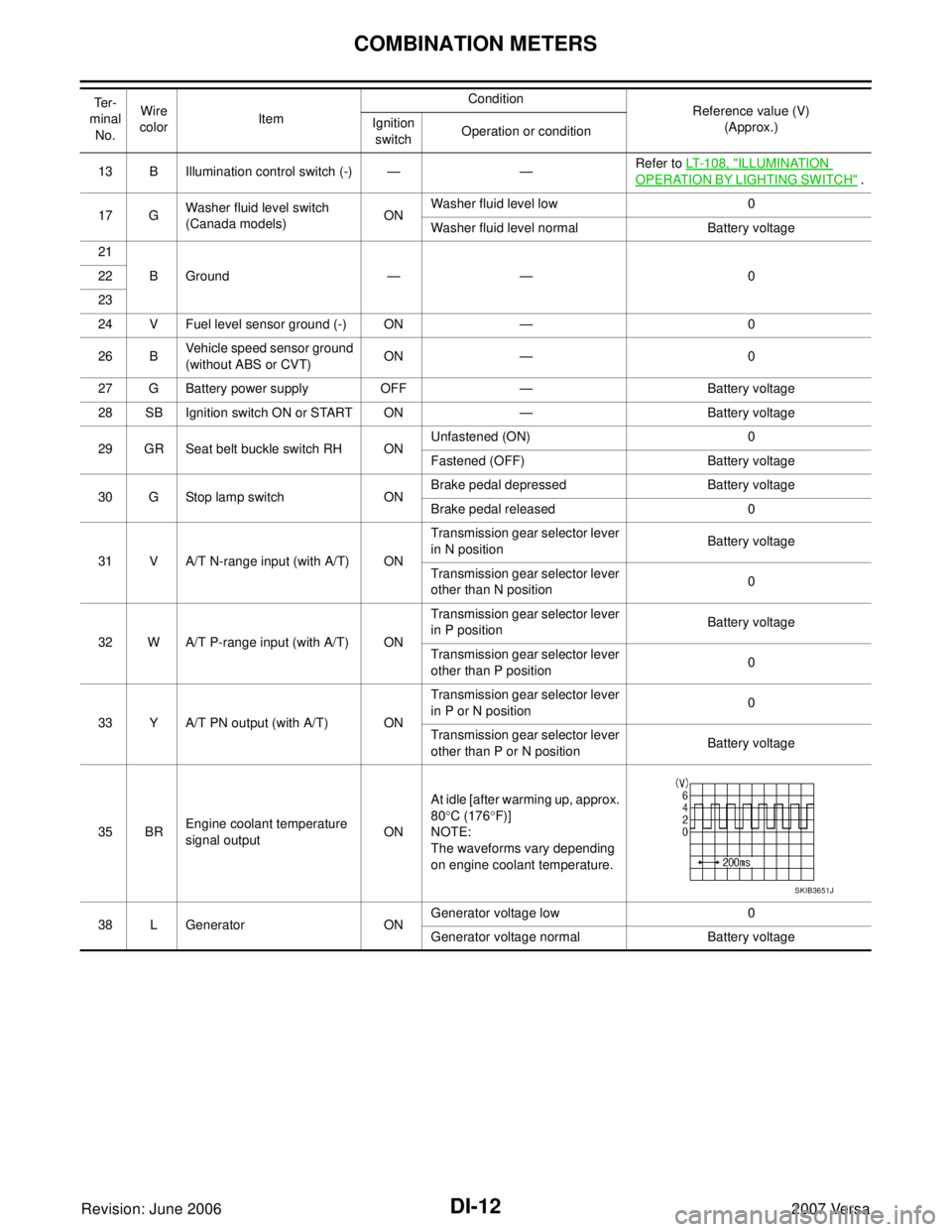
13 B Illumination control switch (-) — —Refer to LT-108, "ILLUMINATION
OPERATION BY LIGHTING SWITCH" .
17 GWasher fluid level switch
(Canada models)ONWasher fluid level low 0
Washer fluid level normal Battery voltage
21
BGround — — 0 22
23
24 V Fuel level sensor ground (-) ON — 0
26 BVehicle speed sensor ground
(without ABS or CVT)ON — 0
27 G Battery power supply OFF — Battery voltage
28 SB Ignition switch ON or START ON — Battery voltage
29 GR Seat belt buckle switch RH ONUnfastened (ON) 0
Fastened (OFF) Battery voltage
30 G Stop lamp switch ONBrake pedal depressed Battery voltage
Brake pedal released 0
31 V A/T N-range input (with A/T) ONTransmission gear selector lever
in N positionBattery voltage
Transmission gear selector lever
other than N position0
32 W A/T P-range input (with A/T) ONTransmission gear selector lever
in P positionBattery voltage
Transmission gear selector lever
other than P position0
33 Y A/T PN output (with A/T) ONTransmission gear selector lever
in P or N position0
Transmission gear selector lever
other than P or N positionBattery voltage
35 BREngine coolant temperature
signal outputONAt idle [after warming up, approx.
80°C (176°F)]
NOTE:
The waveforms vary depending
on engine coolant temperature.
38 L Generator ONGenerator voltage low 0
Generator voltage normal Battery voltage Te r -
minal
No.Wire
colorItemCondition
Reference value (V)
(Approx.) Ignition
switchOperation or condition
SKIB3651J
Page 1123 of 2896
DI-14
COMBINATION METERS
Revision: June 20062007 Versa
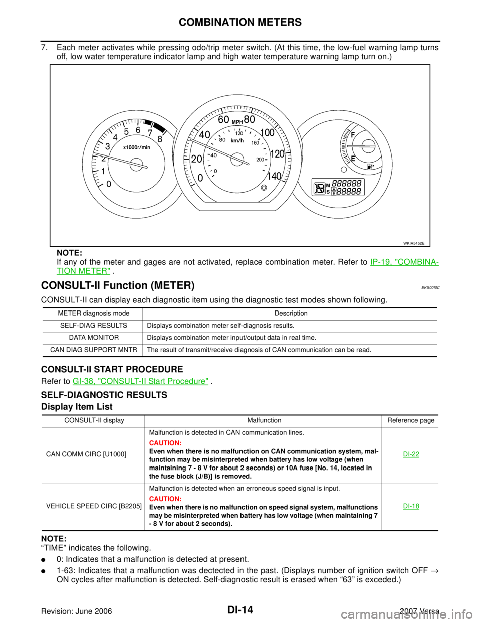
7. Each meter activates while pressing odo/trip meter switch. (At this time, the low-fuel warning lamp turns
off, low water temperature indicator lamp and high water temperature warning lamp turn on.)
NOTE:
If any of the meter and gages are not activated, replace combination meter. Refer to IP-19, "
COMBINA-
TION METER" .
CONSULT-II Function (METER)EKS00I0C
CONSULT-II can display each diagnostic item using the diagnostic test modes shown following.
CONSULT-II START PROCEDURE
Refer to GI-38, "CONSULT-II Start Procedure" .
SELF-DIAGNOSTIC RESULTS
Display Item List
NOTE:
“TIME” indicates the following.
�0: Indicates that a malfunction is detected at present.
�1-63: Indicates that a malfunction was dectected in the past. (Displays number of ignition switch OFF →
ON cycles after malfunction is detected. Self-diagnostic result is erased when “63” is exceded.)
WKIA5452E
METER diagnosis mode Description
SELF-DIAG RESULTS Displays combination meter self-diagnosis results.
DATA MONITOR Displays combination meter input/output data in real time.
CAN DIAG SUPPORT MNTR The result of transmit/receive diagnosis of CAN communication can be read.
CONSULT-II display Malfunction Reference page
CAN COMM CIRC [U1000]Malfunction is detected in CAN communication lines.
CAUTION:
Even when there is no malfunction on CAN communication system, mal-
function may be misinterpreted when battery has low voltage (when
maintaining 7 - 8 V for about 2 seconds) or 10A fuse [No. 14, located in
the fuse block (J/B)] is removed.DI-22
VEHICLE SPEED CIRC [B2205]Malfunction is detected when an erroneous speed signal is input.
CAUTION:
Even when there is no malfunction on speed signal system, malfunctions
may be misinterpreted when battery has low voltage (when maintaining 7
- 8 V for about 2 seconds).DI-18