Page 1126 of 2896
COMBINATION METERS
DI-17
C
D
E
F
G
H
I
J
L
MA
B
DI
Revision: June 20062007 Versa
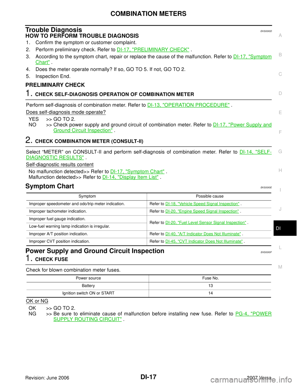
Trouble DiagnosisEKS00I0D
HOW TO PERFORM TROUBLE DIAGNOSIS
1. Confirm the symptom or customer complaint.
2. Perform preliminary check. Refer to DI-17, "
PRELIMINARY CHECK" .
3. According to the symptom chart, repair or replace the cause of the malfunction. Refer to DI-17, "
Symptom
Chart" .
4. Does the meter operate normally? If so, GO TO 5. If not, GO TO 2.
5. Inspection End.
PRELIMINARY CHECK
1. CHECK SELF-DIAGNOSIS OPERATION OF COMBINATION METER
Perform self-diagnosis of combination meter. Refer to DI-13, "
OPERATION PROCEDURE" .
Does self
-diagnosis mode operate?
YES >> GO TO 2.
NO >> Check power supply and ground circuit of combination meter. Refer to DI-17, "
Power Supply and
Ground Circuit Inspection" .
2. CHECK COMBINATION METER (CONSULT-II)
Select “METER” on CONSULT-II and perform self-diagnosis of combination meter. Refer to DI-14, "
SELF-
DIAGNOSTIC RESULTS" .
Self
-diagnostic results content
No malfunction detected>> Refer to DI-17, "Symptom Chart" .
Malfunction detected>> Refer to DI-14, "
Display Item List" .
Symptom Chart EKS00I0E
Power Supply and Ground Circuit InspectionEKS00I0F
1. CHECK FUSE
Check for blown combination meter fuses.
OK or NG
OK >> GO TO 2.
NG >> Be sure to eliminate cause of malfunction before installing new fuse. Refer to PG-4, "
POWER
SUPPLY ROUTING CIRCUIT" .
Symptom Possible cause
Improper speedometer and odo/trip meter indication. Refer to DI-18, "
Vehicle Speed Signal Inspection" .
Improper tachometer indication. Refer to DI-20, "
Engine Speed Signal Inspection" .
Improper fuel gauge indication.
Refer to DI-20, "
Fuel Level Sensor Signal Inspection" .
Low-fuel warning lamp indication is irregular.
Improper A/T position indication. Refer to DI-40, "
A/T Indicator Does Not Illuminate" .
Improper CVT position indication. Refer to DI-45, "
CVT Indicator Does Not Illuminate" .
Power source Fuse No.
Battery 13
Ignition switch ON or START 14
Page 1127 of 2896
DI-18
COMBINATION METERS
Revision: June 20062007 Versa
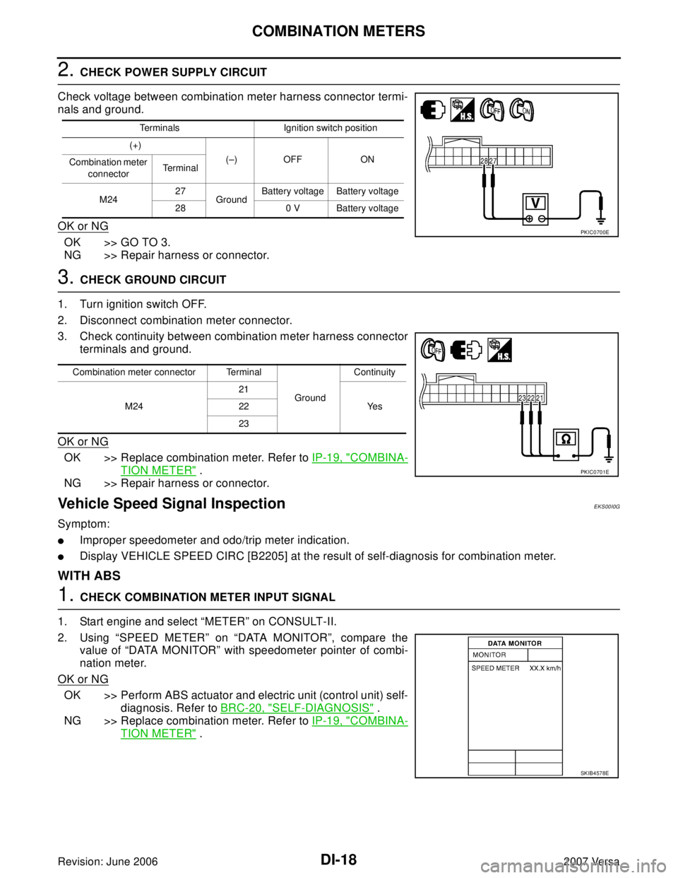
2. CHECK POWER SUPPLY CIRCUIT
Check voltage between combination meter harness connector termi-
nals and ground.
OK or NG
OK >> GO TO 3.
NG >> Repair harness or connector.
3. CHECK GROUND CIRCUIT
1. Turn ignition switch OFF.
2. Disconnect combination meter connector.
3. Check continuity between combination meter harness connector
terminals and ground.
OK or NG
OK >> Replace combination meter. Refer to IP-19, "COMBINA-
TION METER" .
NG >> Repair harness or connector.
Vehicle Speed Signal InspectionEKS00I0G
Symptom:
�Improper speedometer and odo/trip meter indication.
�Display VEHICLE SPEED CIRC [B2205] at the result of self-diagnosis for combination meter.
WITH ABS
1. CHECK COMBINATION METER INPUT SIGNAL
1. Start engine and select “METER” on CONSULT-II.
2. Using “SPEED METER” on “DATA MONITOR”, compare the
value of “DATA MONITOR” with speedometer pointer of combi-
nation meter.
OK or NG
OK >> Perform ABS actuator and electric unit (control unit) self-
diagnosis. Refer to BRC-20, "
SELF-DIAGNOSIS" .
NG >> Replace combination meter. Refer to IP-19, "
COMBINA-
TION METER" .
Terminals Ignition switch position
(+)
(–) OFF ON
Combination meter
connectorTerminal
M2427
GroundBattery voltage Battery voltage
28 0 V Battery voltage
PKIC0700E
Combination meter connector Terminal
GroundContinuity
M2421
Ye s 22
23
PKIC0701E
SKIB4578E
Page 1163 of 2896
DI-54
WARNING CHIME
Revision: June 20062007 Versa
Combination Meter Buzzer Circuit InspectionEKS00I15
1. CHECK CHIME OPERATION
1. Select “BUZZER” of “BCM” on CONSULT-II.
2. Perform “LIGHT WARN ALM” or “IGN KEY WARN ALM” of
“ACTIVE TEST”.
Does chime sound?
YES >> Combination meter buzzer circuit is OK. Return to DI-53,
"SYMPTOM CHART" .
NO >> GO TO 2.
2. CHECK COMBINATION METER INPUT SIGNAL
1. Select “METER” on CONSULT-II.
2. Turn on hazard switch or lighting switch while monitoring
“BUZZER” of “DATA MONITOR” and check operation status.
OK or NG
OK >> Check battery power supply circuit of combination
meter. If OK, replace combination meter. Refer to IP-19,
"COMBINATION METER" .
NG >> Replace BCM. Refer to BCS-25, "
Removal and Installation of BCM" .
SKIA6331E
“BUZZER”
While hazard switch or
lighting switch is ON : ON and OFF repeatedly
Except above : OFF
PKIA2063E
Page 1164 of 2896
WARNING CHIME
DI-55
C
D
E
F
G
H
I
J
L
MA
B
DI
Revision: June 20062007 Versa
Front Door Switch LH Signal InspectionEKS00I16
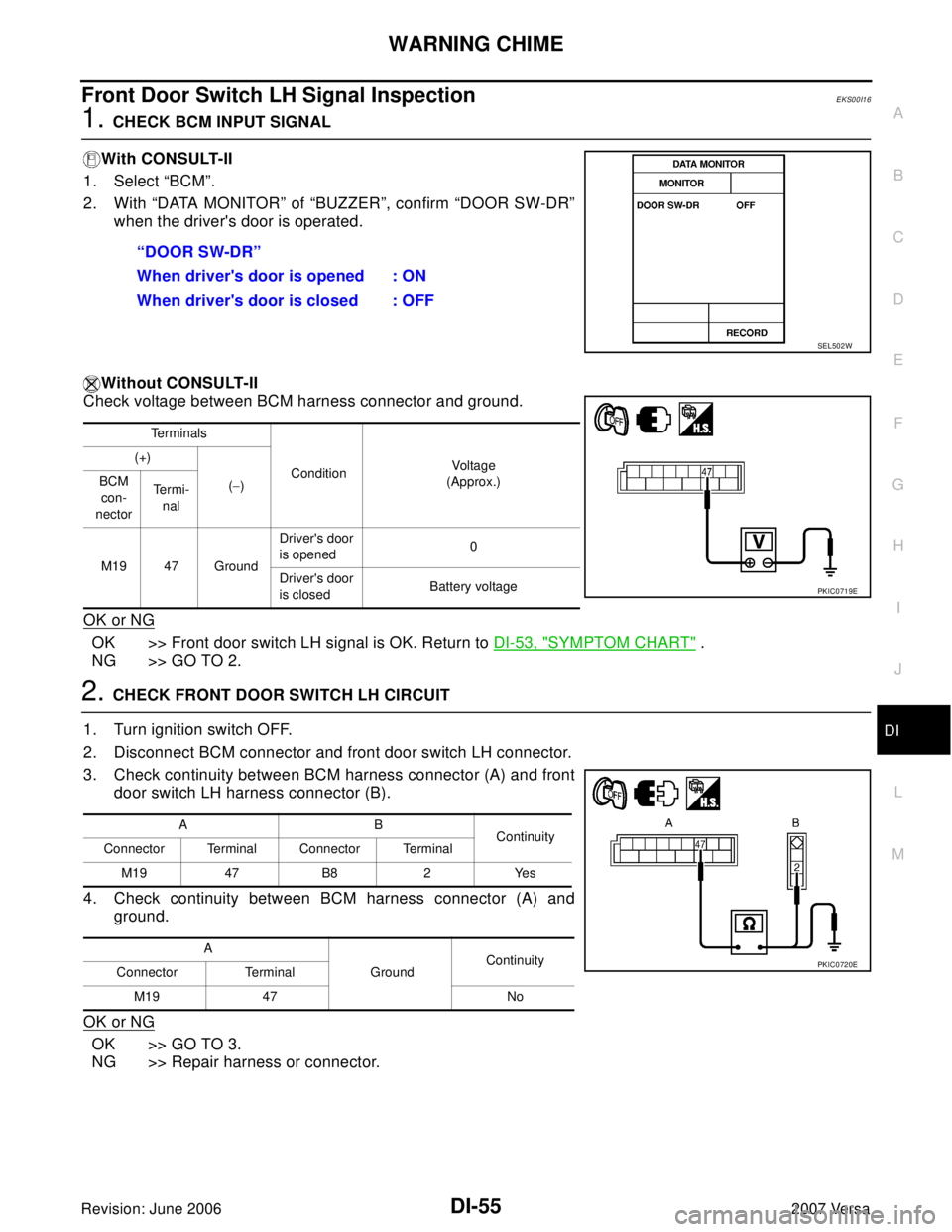
1. CHECK BCM INPUT SIGNAL
With CONSULT-II
1. Select “BCM”.
2. With “DATA MONITOR” of “BUZZER”, confirm “DOOR SW-DR”
when the driver's door is operated.
Without CONSULT-II
Check voltage between BCM harness connector and ground.
OK or NG
OK >> Front door switch LH signal is OK. Return to DI-53, "SYMPTOM CHART" .
NG >> GO TO 2.
2. CHECK FRONT DOOR SWITCH LH CIRCUIT
1. Turn ignition switch OFF.
2. Disconnect BCM connector and front door switch LH connector.
3. Check continuity between BCM harness connector (A) and front
door switch LH harness connector (B).
4. Check continuity between BCM harness connector (A) and
ground.
OK or NG
OK >> GO TO 3.
NG >> Repair harness or connector.“DOOR SW-DR”
When driver's door is opened : ON
When driver's door is closed : OFF
SEL502W
Te r m i n a l s
ConditionVoltage
(Approx.) (+)
(−) BCM
con-
nectorTe r m i -
nal
M19 47 GroundDriver's door
is opened0
Driver's door
is closedBattery voltage
PKIC0719E
AB
Continuity
Connector Terminal Connector Terminal
M19 47 B8 2 Yes
A
GroundContinuity
Connector Terminal
M19 47 No
PKIC0720E
Page 1165 of 2896
DI-56
WARNING CHIME
Revision: June 20062007 Versa
3. CHECK FRONT DOOR SWITCH LH
Check front door switch LH. Refer to DI-60, "
FRONT DOOR SWITCH LH" .
OK or NG
OK >> Replace BCM. Refer to BCS-25, "Removal and Installation of BCM" .
NG >> Replace front door switch LH.
Key Switch Signal Inspection (Without Intelligent Key)EKS00I17
1. CHECK FUSE
Check if the key switch and key lock solenoid 10A fuse [No. 14, located in the fuse block (J/B)] is blown.
OK or NG
OK >> GO TO 2.
NG >> Be sure to repair the cause of malfunction before installing new fuse. Refer to PG-4, "
POWER
SUPPLY ROUTING CIRCUIT" .
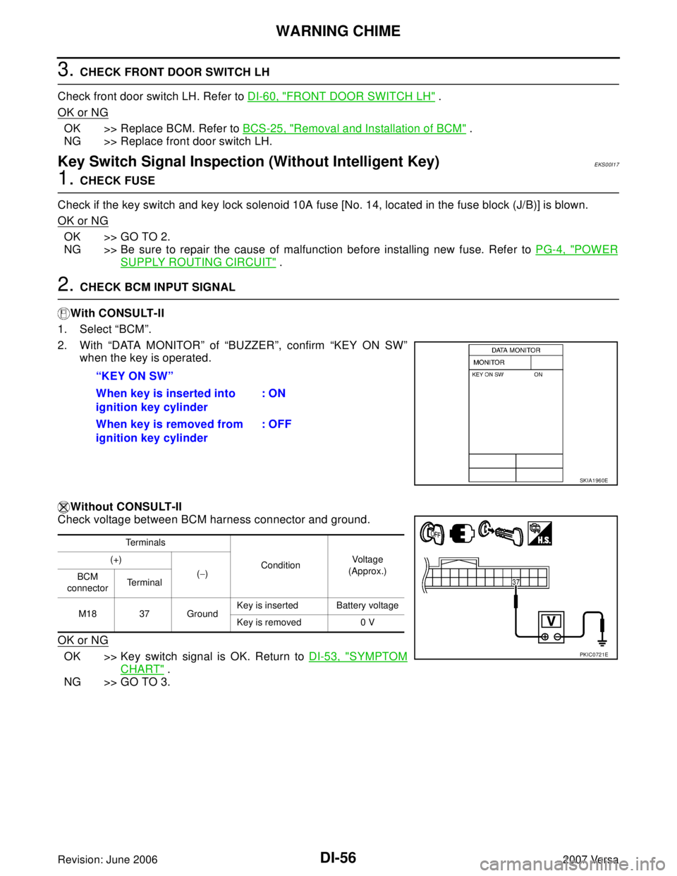
2. CHECK BCM INPUT SIGNAL
With CONSULT-II
1. Select “BCM”.
2. With “DATA MONITOR” of “BUZZER”, confirm “KEY ON SW”
when the key is operated.
Without CONSULT-II
Check voltage between BCM harness connector and ground.
OK or NG
OK >> Key switch signal is OK. Return to DI-53, "SYMPTOM
CHART" .
NG >> GO TO 3.“KEY ON SW”
When key is inserted into
ignition key cylinder: ON
When key is removed from
ignition key cylinder: OFF
SKIA1960E
Te r m i n a l s
ConditionVoltage
(Approx.) (+)
(−)
BCM
connectorTe r m i n a l
M18 37 GroundKey is inserted Battery voltage
Key is removed 0 V
PKIC0721E
Page 1166 of 2896
WARNING CHIME
DI-57
C
D
E
F
G
H
I
J
L
MA
B
DI
Revision: June 20062007 Versa
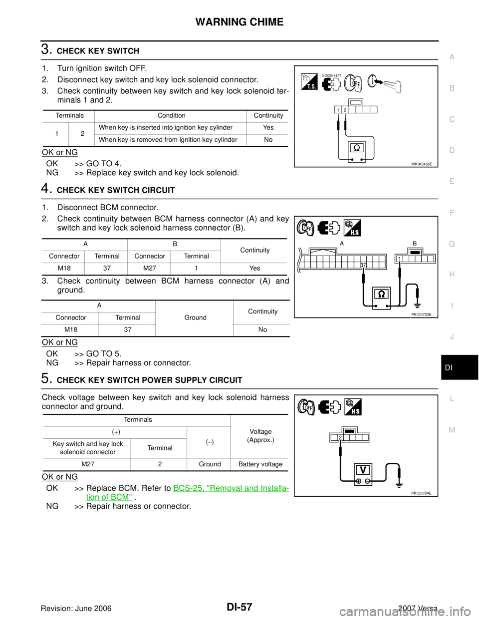
3. CHECK KEY SWITCH
1. Turn ignition switch OFF.
2. Disconnect key switch and key lock solenoid connector.
3. Check continuity between key switch and key lock solenoid ter-
minals 1 and 2.
OK or NG
OK >> GO TO 4.
NG >> Replace key switch and key lock solenoid.
4. CHECK KEY SWITCH CIRCUIT
1. Disconnect BCM connector.
2. Check continuity between BCM harness connector (A) and key
switch and key lock solenoid harness connector (B).
3. Check continuity between BCM harness connector (A) and
ground.
OK or NG
OK >> GO TO 5.
NG >> Repair harness or connector.
5. CHECK KEY SWITCH POWER SUPPLY CIRCUIT
Check voltage between key switch and key lock solenoid harness
connector and ground.
OK or NG
OK >> Replace BCM. Refer to BCS-25, "Removal and Installa-
tion of BCM" .
NG >> Repair harness or connector.
Terminals Condition Continuity
12When key is inserted into ignition key cylinder Yes
When key is removed from ignition key cylinder No
WKIA5466E
AB
Continuity
Connector Terminal Connector Terminal
M1837M27 1 Yes
A
GroundContinuity
Connector Terminal
M18 37 No
PKIC0723E
Te r m i n a l s
Voltage
(Approx.) (+)
(−)
Key switch and key lock
solenoid connectorTe r m i n a l
M27 2 Ground Battery voltage
PKIC0724E
Page 1167 of 2896
DI-58
WARNING CHIME
Revision: June 20062007 Versa
Key Switch and Ignition Knob Switch Signal Inspection (With Intelligent Key,
When Mechanical Key Is Used)
EKS00I18
1. CHECK FUSE
Check if the key switch and ignition knob switch 10A fuse (No. 31, located in the fuse and fusible link box) is
blown.
OK or NG
OK >> GO TO 2.
NG >> Be sure to repair the cause of malfunction before installing new fuse. Refer to PG-4, "
POWER
SUPPLY ROUTING CIRCUIT" .
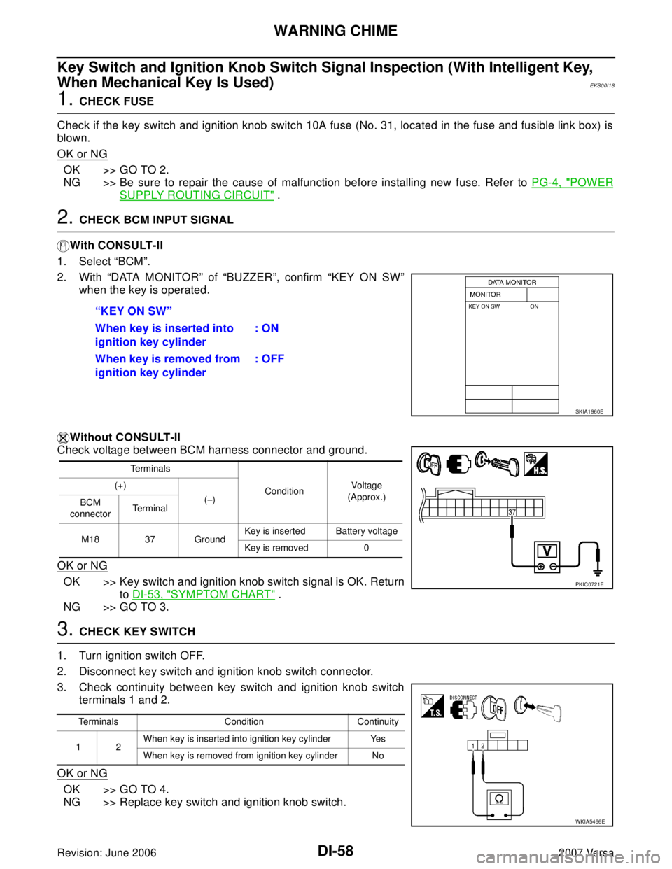
2. CHECK BCM INPUT SIGNAL
With CONSULT-II
1. Select “BCM”.
2. With “DATA MONITOR” of “BUZZER”, confirm “KEY ON SW”
when the key is operated.
Without CONSULT-II
Check voltage between BCM harness connector and ground.
OK or NG
OK >> Key switch and ignition knob switch signal is OK. Return
to DI-53, "
SYMPTOM CHART" .
NG >> GO TO 3.
3. CHECK KEY SWITCH
1. Turn ignition switch OFF.
2. Disconnect key switch and ignition knob switch connector.
3. Check continuity between key switch and ignition knob switch
terminals 1 and 2.
OK or NG
OK >> GO TO 4.
NG >> Replace key switch and ignition knob switch.“KEY ON SW”
When key is inserted into
ignition key cylinder: ON
When key is removed from
ignition key cylinder: OFF
SKIA1960E
Te r m i n a l s
ConditionVo ltag e
(Approx.) (+)
(−)
BCM
connectorTerminal
M18 37 GroundKey is inserted Battery voltage
Key is removed 0
PKIC0721E
Terminals Condition Continuity
12When key is inserted into ignition key cylinder Yes
When key is removed from ignition key cylinder No
WKIA5466E
Page 1168 of 2896
WARNING CHIME
DI-59
C
D
E
F
G
H
I
J
L
MA
B
DI
Revision: June 20062007 Versa
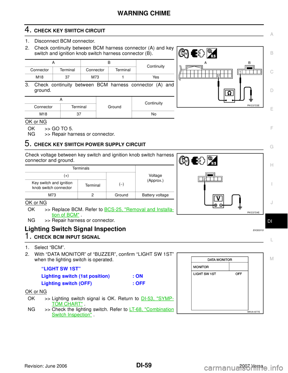
4. CHECK KEY SWITCH CIRCUIT
1. Disconnect BCM connector.
2. Check continuity between BCM harness connector (A) and key
switch and ignition knob switch harness connector (B).
3. Check continuity between BCM harness connector (A) and
ground.
OK or NG
OK >> GO TO 5.
NG >> Repair harness or connector.
5. CHECK KEY SWITCH POWER SUPPLY CIRCUIT
Check voltage between key switch and ignition knob switch harness
connector and ground.
OK or NG
OK >> Replace BCM. Refer to BCS-25, "Removal and Installa-
tion of BCM" .
NG >> Repair harness or connector.
Lighting Switch Signal InspectionEKS00I19
1. CHECK BCM INPUT SIGNAL
1. Select “BCM”.
2. With “DATA MONITOR” of “BUZZER”, confirm “LIGHT SW 1ST”
when the lighting switch is operated.
OK or NG
OK >> Lighting switch signal is OK. Return to DI-53, "SYMP-
TOM CHART" .
NG >> Check the lighting switch. Refer to LT- 6 8 , "
Combination
Switch Inspection" .
AB
Continuity
Connector Terminal Connector Terminal
M1837M73 1 Yes
A
GroundContinuity
Connector Terminal
M18 37 No
PKIC0723E
Te r m i n a l s
Voltage
(Approx.) (+)
(−) Key switch and ignition
knob switch connector Te r m i n a l
M73 2 Ground Battery voltage
PKIC0724E
“LIGHT SW 1ST”
Lighting switch (1st position) : ON
Lighting switch (OFF) : OFF
WKIA1877E