Page 56 of 148
 from its original position.
CAUTION:
Do not remove crankshaft pu")
EM-56
TIMING CHAIN
Revision: 2006 November2007 350Z
b. Loosen crankshaft pulley bolt and rotate bolt seating surface at
10 mm (0.39 in) from its original position.
CAUTION:
Do not remove crankshaft pulley bolt as it will be used as a
supporting point for suitable puller.
c. Place suitable puller tab on holes of crankshaft pulley, and pull
crankshaft pulley through.
CAUTION:
Do not put suitable puller tab on crankshaft pulley periph-
ery, as this will damage internal damper.
11. Remove oil pans (upper and lower). Refer to EM-26, "
OIL PAN AND OIL STRAINER" .
12. Remove front timing chain case as follows:
a. Loosen mounting bolts in reverse order as shown in the figure.
b. Insert suitable tool into the notch at the top of the front timing
chain case as shown (1).
c. Pry off case by moving the tool as shown (2).
�U s e s e a l c u t t e r [ S S T: K V 1 0 1111 0 0 ( J 3 7 2 2 8 ) ] t o c u t l i q u i d g a s -
ket for removal.
CAUTION:
�Do not use screwdriver or something similar.
�After removal, handle front timing chain case carefully so
it does not tilt, cant, or warp under a load.
PBIC1103E
EMQ0477D
PBIC4968E
SEM156F
Page 57 of 148
TIMING CHAIN
EM-57
C
D
E
F
G
H
I
J
K
L
MA
EM
Revision: 2006 November2007 350Z
13. Remove O-ring (1) from rear timing chain case.
14. Remove front oil seal from front timing chain case using suitable
tool.
�Use screwdriver for removal.
CAUTION:
Be careful not to damage front timing chain case.
15. Remove timing chain tensioner (primary) as follows:
a. Remove lower mounting bolt.
b. Loosen upper mounting bolt slowly, and then turn timing chain
tensioner (primary) on the mounting bolt so that plunger is fully
expanded.
NOTE:
Even if plunger is fully expanded, it is not dropped from the body
of timing chain tensioner (primary).
c. Remove upper mounting bolt, and then remove timing chain ten-
sioner (primary).
A : Right bank
B : Left bank
PBIC5041E
PBIC4969E
PBIC3562E
Page 59 of 148
TIMING CHAIN
EM-59
C
D
E
F
G
H
I
J
K
L
MA
EM
Revision: 2006 November2007 350Z
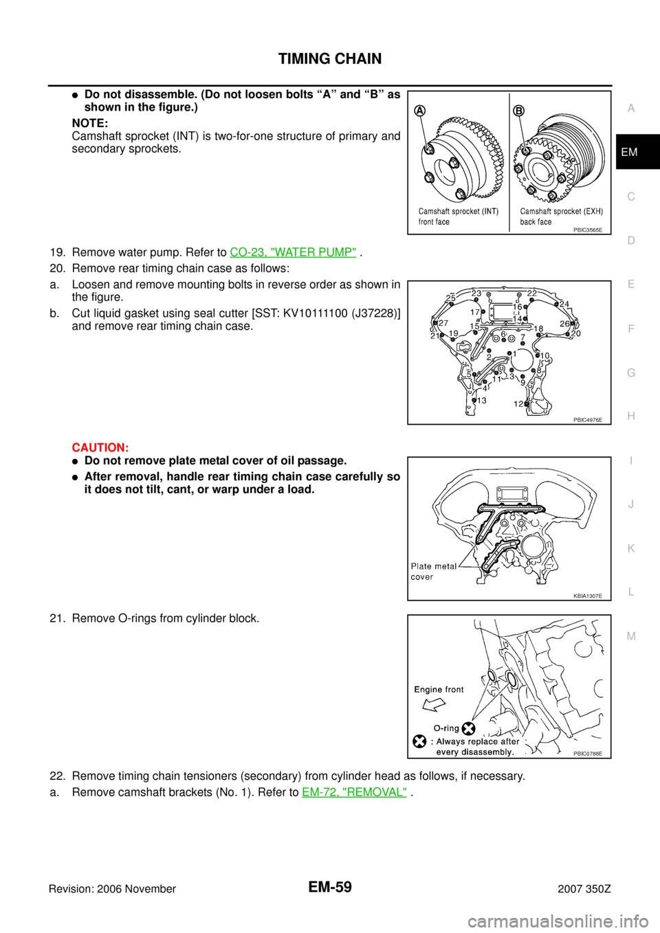
�Do not disassemble. (Do not loosen bolts “A” and “B” as
shown in the figure.)
NOTE:
Camshaft sprocket (INT) is two-for-one structure of primary and
secondary sprockets.
19. Remove water pump. Refer to CO-23, "
WATER PUMP" .
20. Remove rear timing chain case as follows:
a. Loosen and remove mounting bolts in reverse order as shown in
the figure.
b . C u t l i q u i d g a s k e t u s i n g s e a l c u t t e r [ S S T: K V 1 0 1111 0 0 ( J 3 7 2 2 8 ) ]
and remove rear timing chain case.
CAUTION:
�Do not remove plate metal cover of oil passage.
�After removal, handle rear timing chain case carefully so
it does not tilt, cant, or warp under a load.
21. Remove O-rings from cylinder block.
22. Remove timing chain tensioners (secondary) from cylinder head as follows, if necessary.
a. Remove camshaft brackets (No. 1). Refer to EM-72, "
REMOVAL" .
PBIC3565E
PBIC4976E
KBIA1307E
PBIC0788E
Page 63 of 148
 on cylinder block
and install rea")
TIMING CHAIN
EM-63
C
D
E
F
G
H
I
J
K
L
MA
EM
Revision: 2006 November2007 350Z
c. Align rear timing chain case and water pump assembly with dowel pins (right and left) on cylinder block
and install rear timing chain case.
�Make sure O-rings stay in place during installation to cylinder block.
d. Tighten mounting bolts in numerical order as shown in the fig-
ure.
�There are two types of mounting bolts. Refer to the following
for locating bolts.
e. After all bolts are tightened, retighten them to the specified in
numerical order shown in the figure.
�If liquid gasket protrudes, wipe it off immediately.
f. After installing rear timing chain case, check the surface height
difference between following parts on oil pan (upper) mounting
surface.
�If not within standard, repeat the installation procedure.
4. Install water pump with new O-rings. Refer to CO-23, "
WATER PUMP" .
5. Make sure that dowel pin (A) and crankshaft key (1) are located
as shown in the figure. (No. 1 cylinder at compression TDC)
NOTE:
Though camshaft does not stop at the position as shown in the
figure, for the placement of cam nose, it is generally accepted
camshaft is placed for the same direction of the figure.
6. Install timing chains (secondary) and camshaft sprockets as follows:
CAUTION:
�When replacing camshaft sprocket (EXH), replace valve timing control cover (including magnet
retarder and cover).
�Mating marks between timing chain and sprockets slip easily. Confirm all mating mark positions
repeatedly during the installation process.Bolt length: Bolt position
20 mm (0.79 in) : 1, 2, 3, 6, 7, 8, 9, 10
16 mm (0.63 in) : Except the above
: 12.7 N·m (1.3 kg-m, 9 ft-lb)
PBIC4976E
1 : Front timing chain case
2 : Rear timing chain case
3 : Lower cylinder block
Standard
Rear timing chain case to cylinder block:
–0.24 to 0.14 mm (–0.0094 to 0.0055 in)
PBIC4981E
Camshaft dowel pin
: At cylinder head upper face side in each bank.
Crankshaft key
: At cylinder head side of right bank.
PBIC5010E
Page 67 of 148

TIMING CHAIN
EM-67
C
D
E
F
G
H
I
J
K
L
MA
EM
Revision: 2006 November2007 350Z
CAUTION:
Do not overtighten slack guide mounting bolts. It is normal
for a gap to exist under the bolt seats when mounting bolts
are tightened to specification.
9. Install the timing chain tensioner (primary) with the following procedure:
a. Pull plunger stopper tab up (or turn lever downward) so as to
remove plunger stopper tab from the ratchet of plunger.
NOTE:
Plunger stopper tab and lever are synchronized.
b. Push plunger into the inside of tensioner body.
c. Hold plunger in the fully compressed position by engaging
plunger stopper tab with the tip of ratchet.
d. To secure lever, insert stopper pin through hole of lever into ten-
sioner body hole.
�The lever parts and the tab are synchronized. Therefore, the
plunger will be secured under this condition.
NOTE:
Figure shows the example of 1.2 mm (0.047 in) diameter thin screwdriver being used as the stopper pin.
e. Install timing chain tensioner (primary).
�Remove any dirt and foreign materials completely from the
back and the mounting surfaces of timing chain tensioner (pri-
mary).
f. Pull out stopper pin after installing, and then release plunger.
10. Make sure again that the mating marks on sprockets and timing chain have not slipped out of alignment.
11. Install new O-ring (1) on rear timing chain case.
12. Install new front oil seal on front timing chain case.
�Apply new engine oil to both oil seal lip and dust seal lip.
PBIC2633E
PBIC3568E
PBIC3569E
A : Right bank
B : Left bank
PBIC5041E
Page 68 of 148
EM-68
TIMING CHAIN
Revision: 2006 November2007 350Z
�Install it so that each seal lip is oriented as shown in the fig-
ure.
�Using suitable drift (1), press-fit oil seal until it becomes flush
with front timing chain case end face.
�Make sure the garter spring is in position and seal lip is not
inverted.
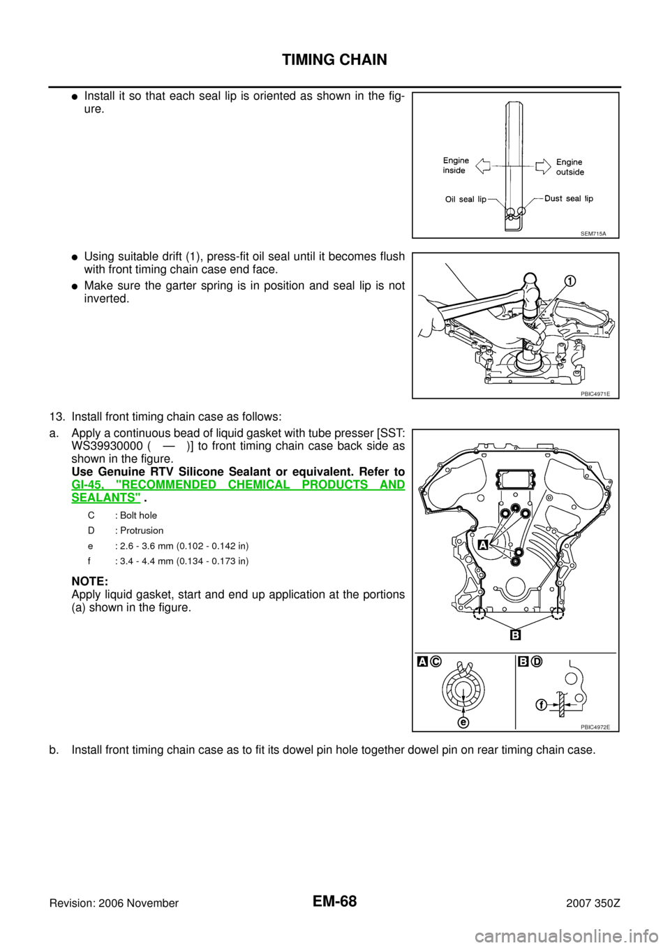
13. Install front timing chain case as follows:
a. Apply a continuous bead of liquid gasket with tube presser [SST:
WS39930000 ( — )] to front timing chain case back side as
shown in the figure.
Use Genuine RTV Silicone Sealant or equivalent. Refer to
GI-45, "
RECOMMENDED CHEMICAL PRODUCTS AND
SEALANTS" .
NOTE:
Apply liquid gasket, start and end up application at the portions
(a) shown in the figure.
b. Install front timing chain case as to fit its dowel pin hole together dowel pin on rear timing chain case.
SEM715A
PBIC4971E
C: Bolt hole
D : Protrusion
e : 2.6 - 3.6 mm (0.102 - 0.142 in)
f : 3.4 - 4.4 mm (0.134 - 0.173 in)
PBIC4972E
Page 69 of 148

TIMING CHAIN
EM-69
C
D
E
F
G
H
I
J
K
L
MA
EM
Revision: 2006 November2007 350Z
c. Tighten mounting bolts to the specified torque in numerical order
as shown in the figure.
�There are two types of mounting bolts. Refer to the following
for locating bolts.
d. After all bolts are tightened, retighten them to the specified
torque in numerical order shown in the figure.
CAUTION:
Be sure to wipe off any excessive liquid gasket leaking on surface mating with oil pan (upper).
e. After installing front timing chain case, check the surface height
difference between the following parts on the oil pan (upper)
mounting surface.
�If not within standard, repeat the installation procedure.
14. Install right and left valve timing control covers as follows:
a. Install new seal rings (1) in shaft grooves.
CAUTION:
When replacing seal rings, replace all rings with new one.
b. To check the joint between dowel pins and dowel pin holes,
check the looseness in the axle direction by pushing the mating
surface of magnet retarder (A) at several places and the circum-
ferential looseness (between dowel pins and dowel pin holes) by
twisting in the circumferential direction.
CAUTION:
Always perform this procedure when removing because the
gap between dowel pins and dowel pin holes may not be
caused on purpose.M8 bolts : 1, 2, 3, 4, 5, 6, 7
: 55.0 N·m (5.6 kg-m, 41 ft-lb)
M6 bolts : Except the above
: 12.7 N·m (1.3 kg-m, 9 ft-lb)
1 : Front timing chain case
2 : Rear timing chain case
3 : Lower cylinder block
Standard
Front timing chain case to rear timing chain case:
–0.14 to 0.14 mm (–0.005 to 0.0055 in)
PBIC4968E
PBIC4981E
A : Left bank
PBIC4973E
B : Moves slightly
C : Not shaken
PBIC4974E
Page 70 of 148

EM-70
TIMING CHAIN
Revision: 2006 November2007 350Z
c. Install valve timing control cover to front timing chain case.
CAUTION:
�Do not face the magnet retarder side down to prevent
magnet retarder from dropping.
�Check the mating surface of magnet retarder and the
drum of exhaust side camshaft sprocket for foreign mate-
rials.
�Align the center of both shaft holes of the shaft and the
intake side camshaft sprocket, and then insert them.
�Be careful not to drop the seal ring from the shaft groove.
�When setting the valve timing control cover in position
by hand, if valve timing control cover is not contacting with the front timing chain case, the
dowel pin of magnet retarder may not be aligned with the dowel pin holes of cover. In this case,
return to step “b”.
d. Tighten mounting bolts in numerical order as shown in the fig-
ure.
CAUTION:
Completely tighten the mounting bolts with the seat surface
of valve timing control cover contacting with front timing
chain case.
�After all bolts are tightened, tighten No.1 bolt to the specified torque again.
15. Install oil pans (upper and lower). Refer to EM-26, "
OIL PAN AND OIL STRAINER" .
16. Install rocker covers (right and left banks). Refer to EM-40, "
ROCKER COVER" .
17. Install crankshaft pulley as follows:
a. Fix crankshaft using ring gear stopper [SST: KV10118600 (J-48641)].
b. Install crankshaft pulley, taking care not to damage front oil seal.
�When press-fitting crankshaft pulley with plastic hammer, tap on its center portion (not circumference).
c. Tighten crankshaft pulley bolt.
d. Place a paint mark (A) on crankshaft pulley (2) aligning with the
angle mark (C) on crankshaft pulley bolt (1). Tighten the bolt 90
degrees (one marks) (b).
18. Rotate crankshaft pulley in normal direction (clockwise when viewed from engine front) to confirm it turns
smoothly.
19. Install in the reverse order of removal after this step.: 11.3 N·m (1.2 kg-m, 8 ft-lb)
A : Right bank
B : Left bank
C : Dowel pin hole
: 44.1 N·m (4.5 kg-m, 33 ft-lb)
PBIC3561E
PBIC4965E
PBIC4975E
 from rear timing chain case.
14. Remove front oil seal from front timing chain case using suitable
t")