Page 86 of 148

EM-86
OIL SEAL
Revision: 2006 November2007 350Z
OIL SEALPFP:00100
Removal and Installation of Valve Oil SealNBS0000V
REMOVAL
1. Remove camshaft relating to valve oil seal to be removed. Refer to EM-72, "CAMSHAFT" .
2. Remove valve lifters. Refer to EM-72, "
CAMSHAFT" .
3. Turn crankshaft until the cylinder requiring new oil seals is at TDC. This will prevent valve from dropping
into cylinder.
4. Remove valve collet.
�Compress valve spring with valve spring compressor, attach-
ment, adapter (SST). Remove valve collet with magnet hand.
CAUTION:
When working, take care not to damage valve lifter holes.
5. Remove valve spring retainer, valve spring and valve spring seat.
6. Remove valve oil seal using valve oil seal puller (SST).
INSTALLATION
1. Apply engine oil on new valve oil seal joint and seal lip.
2. Using valve oil seal drift (SST), press fit valve oil seal to height
“H” shown in the figure.
NOTE:
Dimension “H”: Height measured before valve spring seat instal-
lation
3. Install in the reverse order of removal after this step.
PBIC1803E
PBIC0884E
Intake and exhaust : 14.3 - 14.9 mm (0.563 - 0.587 in)
PBIC0802E
Page 87 of 148

OIL SEAL
EM-87
C
D
E
F
G
H
I
J
K
L
MA
EM
Revision: 2006 November2007 350Z
Removal and Installation of Front Oil SealNBS0000W
REMOVAL
1. Remove the following parts:
�Undercover
�Drive belts: Refer to EM-12, "DRIVE BELTS" .
�Radiator cooling fan assembly: Refer to CO-21, "COOLING FAN" .
�Crankshaft pulley: Refer to EM-53, "TIMING CHAIN" .
2. Remove front oil seal using suitable tool.
CAUTION:
Be careful not to damage front timing chain case and crank-
shaft.
INSTALLATION
1. Apply engine oil to both oil seal lip and dust seal lip of new front oil seal.
2. Install front oil seal.
�Install front oil seal so that each seal lip is oriented as shown
in the figure.
�Using suitable drift, press-fit until the height of front oil seal is
level with the mounting surface.
–Suitable drift: outer diameter 60 mm (2.36 in), inner diameter
50 mm (1.97 in).
CAUTION:
�Be careful not to damage front timing chain case and
crankshaft.
�Press-fit straight and avoid causing burrs or tilting oil
seal.
3. Install in the reverse order of removal after this step.
Removal and Installation of Rear Oil SealNBS0000X
REMOVAL
1. Remove transmission assembly. Refer to MT-18, "TRANSMISSION ASSEMBLY" (M/T models) or AT-
242, "TRANSMISSION ASSEMBLY" (A/T models).
2. Remove clutch cover and clutch disk (M/T models). Refer to CL-16, "
CLUTCH DISC, CLUTCH COVER" .
3. Remove flywheel (M/T models) or drive plate (A/T models). Refer to EM-107, "
CYLINDER BLOCK" .
PBIC2931E
SEM715A
PBIC2931E
Page 88 of 148
EM-88
OIL SEAL
Revision: 2006 November2007 350Z
4. Remove rear oil seal with a suitable tool.
CAUTION:
Be careful not to damage crankshaft and cylinder block.
INSTALLATION
1. Apply new engine oil to new rear oil seal joint surface and seal lip.
2. Install rear oil seal so that each seal lip is oriented as shown.
�Press in rear oil seal to the position as shown.
�Using suitable drift, press-fit until the height of front oil seal is
level with the mounting surface.
–Suitable drift: outer diameter 100 mm (3.94 in), inner diameter
85 mm (3.35 in).
CAUTION:
�Be careful not to damage crankshaft and cylinder block.
�Press-fit oil seal straight to avoid causing burrs or tilting.
3. Install in the reverse order of removal after this step.
PBIC2932E
SEM715A
SBIA0281E
LBIA0454E
Page 92 of 148

EM-92
CYLINDER HEAD
Revision: 2006 November2007 350Z
2. At each of several locations on bottom surface of cylinder head,
measure the distortion in six directions.
�If it exceeds the limit, replace cylinder head.
INSTALLATION
1. Install new cylinder head gaskets.
2. Turn crankshaft until No. 1 piston is set at TDC.
�Crankshaft key should line up with the right bank cylinder cen-
ter line as shown in the figure.
3. Install cylinder head follow the steps below to tighten cylinder
head bolts in numerical order as shown in the figure.
CAUTION:
If cylinder head bolts re-used, check their outer diameters
before installation. Refer to EM-91, "
Cylinder Head Bolts
Outer Diameter" .
a. Apply new engine oil to threads and seat surfaces of cylinder
head bolts.
b. Tighten all cylinder head bolts.
c. Completely loosen all cylinder head bolts.
CAUTION:
In step “c”, loosen bolts in reverse order of that indicated in
the figure.
d. Tighten all cylinder head bolts.Limit : 0.1 mm (0.004 in)
SEM861E
1 : Crankshaft key
: Right bank side
PBIC5012E
: 105 N·m (11 kg-m, 77 ft-lb)
: 0 N·m (0 kg-m, 0 ft-lb)
: 39.2 N·m (4.0 kg-m, 29 ft-lb)
PBIC2057E
Page 107 of 148
CYLINDER BLOCK
EM-107
C
D
E
F
G
H
I
J
K
L
MA
EM
Revision: 2006 November2007 350Z
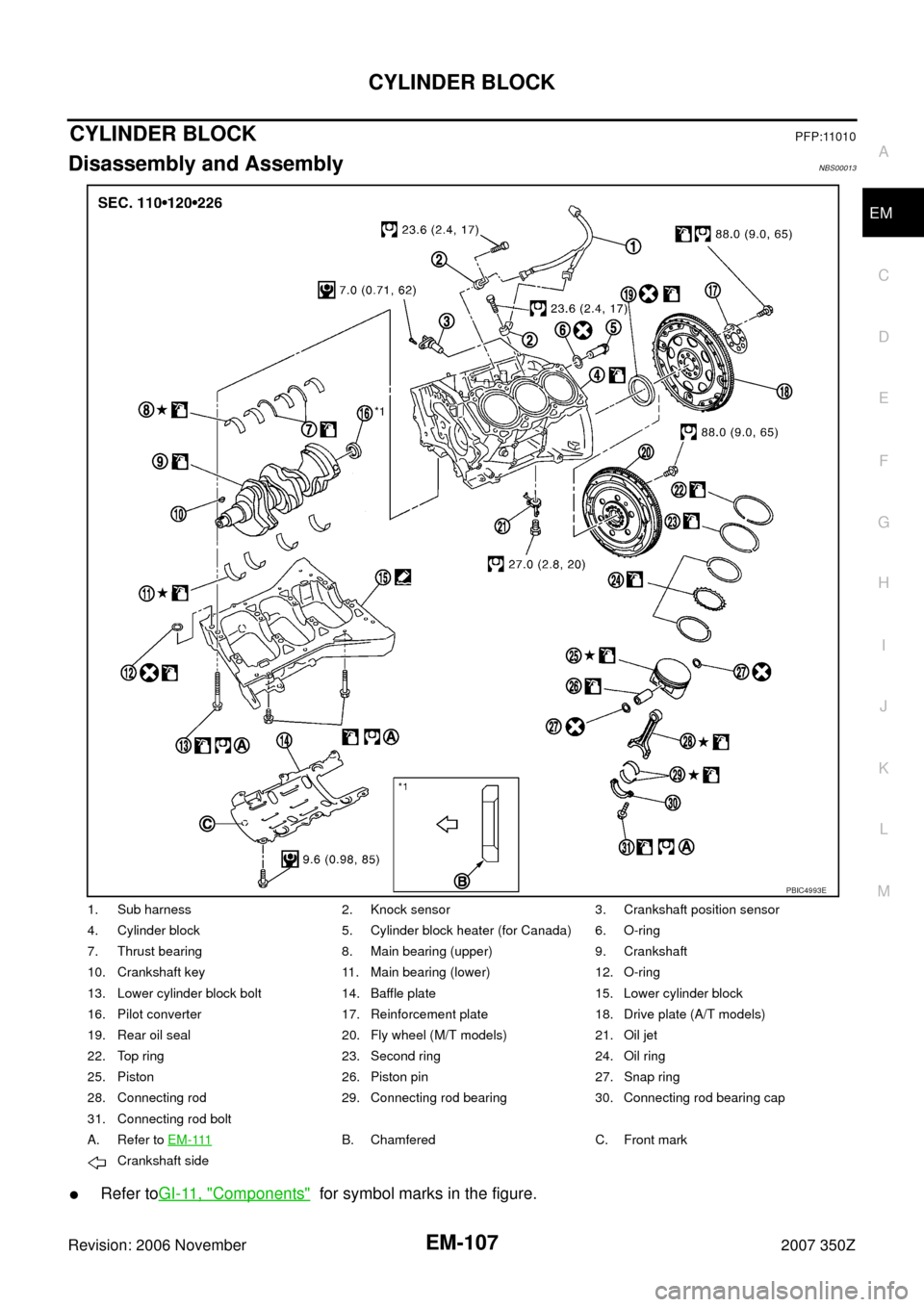
CYLINDER BLOCKPFP:11010
Disassembly and AssemblyNBS00013
�Refer toGI-11, "Components" for symbol marks in the figure.
1. Sub harness 2. Knock sensor 3. Crankshaft position sensor
4. Cylinder block 5. Cylinder block heater (for Canada) 6. O-ring
7. Thrust bearing 8. Main bearing (upper) 9. Crankshaft
10. Crankshaft key 11. Main bearing (lower) 12. O-ring
13. Lower cylinder block bolt 14. Baffle plate 15. Lower cylinder block
16. Pilot converter 17. Reinforcement plate 18. Drive plate (A/T models)
19. Rear oil seal 20. Fly wheel (M/T models) 21. Oil jet
22. Top ring 23. Second ring 24. Oil ring
25. Piston 26. Piston pin 27. Snap ring
28. Connecting rod 29. Connecting rod bearing 30. Connecting rod bearing cap
31. Connecting rod bolt
A. Refer to E M - 111
B. Chamfered C. Front mark
Crankshaft side
PBIC4993E
Page 108 of 148

EM-108
CYLINDER BLOCK
Revision: 2006 November2007 350Z
DISASSEMBLY
1. Remove engine assembly from vehicle, and separate front suspension member and transmission from
engine. Refer to EM-101, "
ENGINE ASSEMBLY" .
2. Remove engine mounting brackets (RH and LH). Refer to EM-101, "
ENGINE ASSEMBLY" .
3. Remove the parts that may restrict installation of engine to widely use engine stand.
NOTE:
The procedure is described assuming that you use a widely use engine stand holding the surface, to
which transmission is installed.
�Remove clutch cover and clutch disk (M/T models). Refer to CL-16, "CLUTCH DISC, CLUTCH
COVER" .
�Remove flywheel (M/T models) or drive plate (A/T models). Fix crankshaft with a ring gear stopper
[SST: KV10118600 (J-48641)], and remove mounting bolts.
�Loosen mounting bolts in diagonal order.
�Check for deformation or damage (A).
CAUTION:
�Do not disassemble drive plate.
�Never place drive plate with signal plate facing down.
�When handling signal plate, take care not to damage or
scratch it.
�Handle signal plate in a manner that prevents it from
becoming magnetized.
4. Remove pilot bushing (M/T models) or pilot converter (A/T mod-
els) using pilot bushing puller [SST: ST16610001 (J-23907)] (A)
or suitable tool as necessary.
5. Lift the engine with hoist to install it onto the widely use engine stand.
�A widely use engine stand can be used.
CAUTION:
Use engine stand that has a load capacity [approximately
220 kg (485 lb) or more] large enough for supporting the
engine weight.
NOTE:
This example is engine stand for holding at transmission
mounting side with flywheel (M/T models) or drive plate (A/T
models) removed.
6. Drain engine oil. Refer to LU-7, "
Changing Engine Oil" .
SEM760G
PBIC5015E
PBIC0085E
Page 109 of 148
 from
cylinder block both sides as shown in the figure.
8.")
CYLINDER BLOCK
EM-109
C
D
E
F
G
H
I
J
K
L
MA
EM
Revision: 2006 November2007 350Z
7. Drain engine coolant by removing water drain plugs (1, 4) from
cylinder block both sides as shown in the figure.
8. Remove oil pan (upper, lower). Refer to EM-26, "
OIL PAN AND OIL STRAINER" .
9. Remove front timing chain case, timing chain and rear timing chain case. Refer to EM-53, "
TIMING
CHAIN" .
10. Remove cylinder head. Refer to EM-89, "
CYLINDER HEAD" .
11. Remove knock sensor.
CAUTION:
Carefully handle sensor avoiding shocks.
12. Remove rear oil seal.
13. Remove baffle plate from lower cylinder block.
14. Remove piston and connecting rod assembly as follows:
�Before removing piston and connecting rod assembly, check the connecting rod side clearance. Refer
to EM-125, "
CONNECTING ROD SIDE CLEARANCE" .
a. Position crankshaft pin corresponding to connecting rod to be removed onto the bottom dead center.
b. Remove connecting rod bearing cap.
c. Using hammer handle or similar tool, push piston and connect-
ing rod assembly out to the cylinder head side.
CAUTION:
Be careful not to damage the cylinder wall and crankshaft
pin, resulting from an interference of the connecting rod big
end.
15. Remove connecting rod bearings from connecting rod and connecting rod bearing cap.
CAUTION:
Identify installation position, and store them without mixing them up.
16. Remove piston rings form piston.
�Before removing piston rings, check the piston ring side clearance. Refer to EM-126, "PISTON RING
SIDE CLEARANCE" .
2 : Washer
3: Plug
: Engine front
PBIC5014E
PBIC2940E
Page 110 of 148
EM-110
CYLINDER BLOCK
Revision: 2006 November2007 350Z
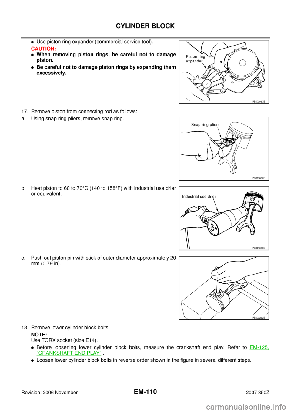
�Use piston ring expander (commercial service tool).
CAUTION:
�When removing piston rings, be careful not to damage
piston.
�Be careful not to damage piston rings by expanding them
excessively.
17. Remove piston from connecting rod as follows:
a. Using snap ring pliers, remove snap ring.
b. Heat piston to 60 to 70°C (140 to 158°F) with industrial use drier
or equivalent.
c. Push out piston pin with stick of outer diameter approximately 20
mm (0.79 in).
18. Remove lower cylinder block bolts.
NOTE:
Use TORX socket (size E14).
�Before loosening lower cylinder block bolts, measure the crankshaft end play. Refer to EM-125,
"CRANKSHAFT END PLAY" .
�Loosen lower cylinder block bolts in reverse order shown in the figure in several different steps.
PBIC0087E
PBIC1638E
PBIC1639E
PBIC0262E