Page 79 of 148

CAMSHAFT
EM-79
C
D
E
F
G
H
I
J
K
L
MA
EM
Revision: 2006 November2007 350Z
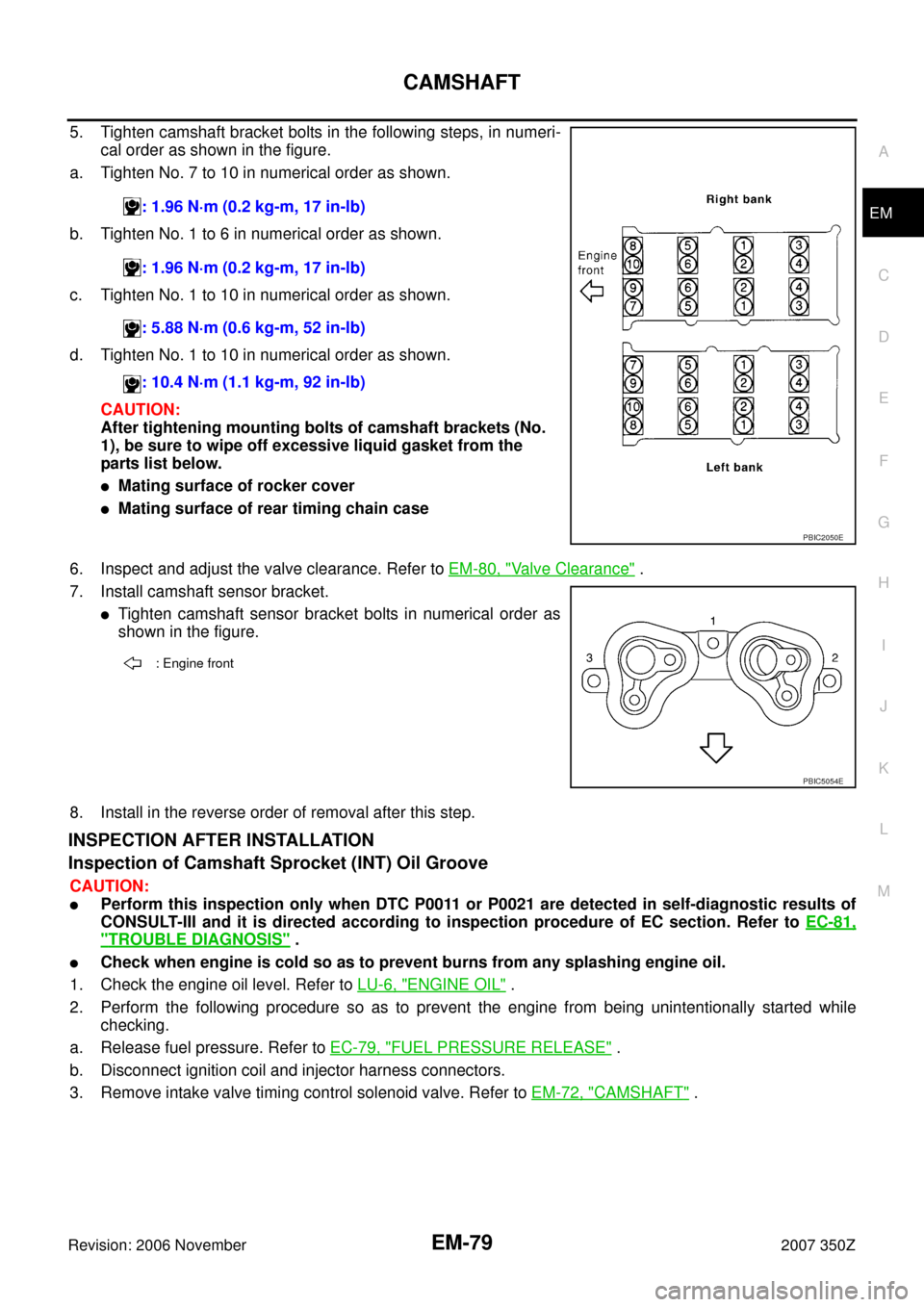
5. Tighten camshaft bracket bolts in the following steps, in numeri-
cal order as shown in the figure.
a. Tighten No. 7 to 10 in numerical order as shown.
b. Tighten No. 1 to 6 in numerical order as shown.
c. Tighten No. 1 to 10 in numerical order as shown.
d. Tighten No. 1 to 10 in numerical order as shown.
CAUTION:
After tightening mounting bolts of camshaft brackets (No.
1), be sure to wipe off excessive liquid gasket from the
parts list below.
�Mating surface of rocker cover
�Mating surface of rear timing chain case
6. Inspect and adjust the valve clearance. Refer to EM-80, "
Valve Clearance" .
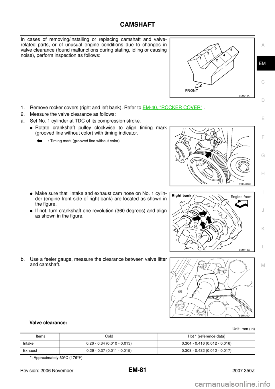
7. Install camshaft sensor bracket.
�Tighten camshaft sensor bracket bolts in numerical order as
shown in the figure.
8. Install in the reverse order of removal after this step.
INSPECTION AFTER INSTALLATION
Inspection of Camshaft Sprocket (INT) Oil Groove
CAUTION:
�Perform this inspection only when DTC P0011 or P0021 are detected in self-diagnostic results of
CONSULT-III and it is directed according to inspection procedure of EC section. Refer to EC-81,
"TROUBLE DIAGNOSIS" .
�Check when engine is cold so as to prevent burns from any splashing engine oil.
1. Check the engine oil level. Refer to LU-6, "
ENGINE OIL" .
2. Perform the following procedure so as to prevent the engine from being unintentionally started while
checking.
a. Release fuel pressure. Refer to EC-79, "
FUEL PRESSURE RELEASE" .
b. Disconnect ignition coil and injector harness connectors.
3. Remove intake valve timing control solenoid valve. Refer to EM-72, "
CAMSHAFT" . : 1.96 N·m (0.2 kg-m, 17 in-lb)
: 1.96 N·m (0.2 kg-m, 17 in-lb)
: 5.88 N·m (0.6 kg-m, 52 in-lb)
: 10.4 N·m (1.1 kg-m, 92 in-lb)
PBIC2050E
: Engine front
PBIC5054E
Page 81 of 148

CAMSHAFT
EM-81
C
D
E
F
G
H
I
J
K
L
MA
EM
Revision: 2006 November2007 350Z
In cases of removing/installing or replacing camshaft and valve-
related parts, or of unusual engine conditions due to changes in
valve clearance (found malfunctions during stating, idling or causing
noise), perform inspection as follows:
1. Remove rocker covers (right and left bank). Refer to EM-40, "
ROCKER COVER" .
2. Measure the valve clearance as follows:
a. Set No. 1 cylinder at TDC of its compression stroke.
�Rotate crankshaft pulley clockwise to align timing mark
(grooved line without color) with timing indicator.
�Make sure that intake and exhaust cam nose on No. 1 cylin-
der (engine front side of right bank) are located as shown in
the figure.
�If not, turn crankshaft one revolution (360 degrees) and align
as shown in the figure.
b. Use a feeler gauge, measure the clearance between valve lifter
and camshaft.
Valve clearance:
Unit: mm (in)
*: Approximately 80°C (176°F)
SEM713A
: Timing mark (grooved line without color)
PBIC4966E
SEM418G
SEM139D
Items Cold Hot * (reference data)
Intake 0.26 - 0.34 (0.010 - 0.013) 0.304 - 0.416 (0.012 - 0.016)
Exhaust 0.29 - 0.37 (0.011 - 0.015) 0.308 - 0.432 (0.012 - 0.017)
Page 87 of 148

OIL SEAL
EM-87
C
D
E
F
G
H
I
J
K
L
MA
EM
Revision: 2006 November2007 350Z
Removal and Installation of Front Oil SealNBS0000W
REMOVAL
1. Remove the following parts:
�Undercover
�Drive belts: Refer to EM-12, "DRIVE BELTS" .
�Radiator cooling fan assembly: Refer to CO-21, "COOLING FAN" .
�Crankshaft pulley: Refer to EM-53, "TIMING CHAIN" .
2. Remove front oil seal using suitable tool.
CAUTION:
Be careful not to damage front timing chain case and crank-
shaft.
INSTALLATION
1. Apply engine oil to both oil seal lip and dust seal lip of new front oil seal.
2. Install front oil seal.
�Install front oil seal so that each seal lip is oriented as shown
in the figure.
�Using suitable drift, press-fit until the height of front oil seal is
level with the mounting surface.
–Suitable drift: outer diameter 60 mm (2.36 in), inner diameter
50 mm (1.97 in).
CAUTION:
�Be careful not to damage front timing chain case and
crankshaft.
�Press-fit straight and avoid causing burrs or tilting oil
seal.
3. Install in the reverse order of removal after this step.
Removal and Installation of Rear Oil SealNBS0000X
REMOVAL
1. Remove transmission assembly. Refer to MT-18, "TRANSMISSION ASSEMBLY" (M/T models) or AT-
242, "TRANSMISSION ASSEMBLY" (A/T models).
2. Remove clutch cover and clutch disk (M/T models). Refer to CL-16, "
CLUTCH DISC, CLUTCH COVER" .
3. Remove flywheel (M/T models) or drive plate (A/T models). Refer to EM-107, "
CYLINDER BLOCK" .
PBIC2931E
SEM715A
PBIC2931E
Page:
< prev 1-8 9-16 17-24