Page 95 of 260
DOOR
BL-95
C
D
E
F
G
H
J
K
L
MA
B
BL
Revision: 2006 November2007 350Z
DOVE TAIL FEMALE ADJUSTMENT (ROADSTER)
Adjust the dove tail female so that it becomes parallel with the lock
insertion direction.
Removal and InstallationNIS0001Y
CAUTION:
�When removing and installing the door assembly, support the door with a jack and cloth to protect
the door and body.
�When removing and installing door assembly, be sure to perform the fitting adjustment Refer to
BL-93, "
Fitting Adjustment" .
�Operate with two workers, because of its heavy weight.
�Check the hinge rotating part for poor lubrication. If necessary, apply “body grease”.
�After installing, check operation.
�Apply sealant and coat with the same body color paint to door hinge installation part and mount-
ing nuts.
REMOVAL
1. Pull the lever and remove the door harness connector while
removing tabs of door harness connector.
2. Remove the mounting bolts of the check link on the vehicle.
PIIA7608E
PIIA2514E
PIIA2515E
Page 98 of 260
BL-98
DOOR LOCK
Revision: 2006 November2007 350Z
DOOR LOCKPFP:80502
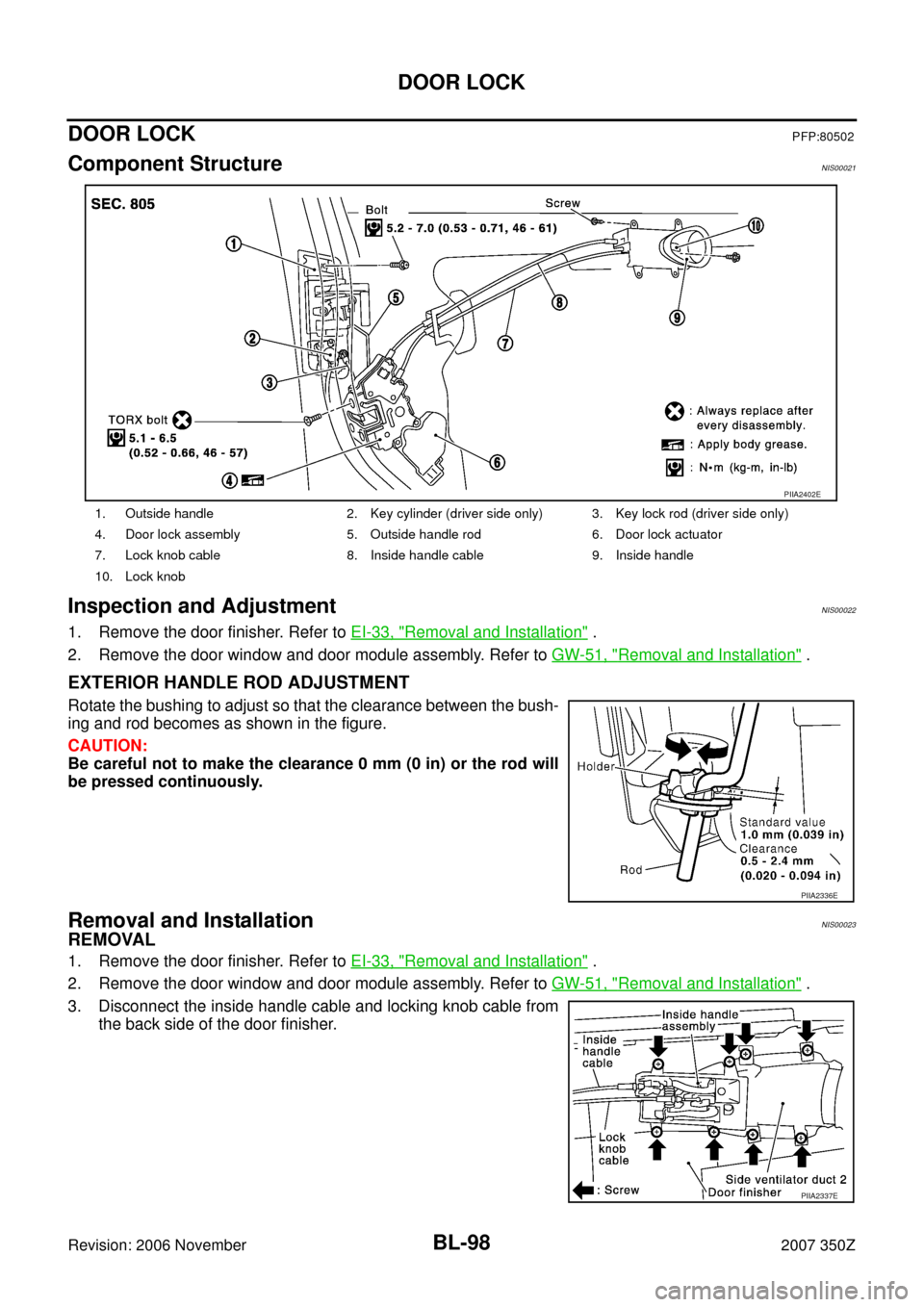
Component StructureNIS00021
Inspection and AdjustmentNIS00022
1. Remove the door finisher. Refer to EI-33, "Removal and Installation" .
2. Remove the door window and door module assembly. Refer to GW-51, "
Removal and Installation" .
EXTERIOR HANDLE ROD ADJUSTMENT
Rotate the bushing to adjust so that the clearance between the bush-
ing and rod becomes as shown in the figure.
CAUTION:
Be careful not to make the clearance 0 mm (0 in) or the rod will
be pressed continuously.
Removal and InstallationNIS00023
REMOVAL
1. Remove the door finisher. Refer to EI-33, "Removal and Installation" .
2. Remove the door window and door module assembly. Refer to GW-51, "
Removal and Installation" .
3. Disconnect the inside handle cable and locking knob cable from
the back side of the door finisher.
1. Outside handle 2. Key cylinder (driver side only) 3. Key lock rod (driver side only)
4. Door lock assembly 5. Outside handle rod 6. Door lock actuator
7. Lock knob cable 8. Inside handle cable 9. Inside handle
10. Lock knob
PIIA2402E
PIIA2336E
PIIA2337E
Page 99 of 260
DOOR LOCK
BL-99
C
D
E
F
G
H
J
K
L
MA
B
BL
Revision: 2006 November2007 350Z
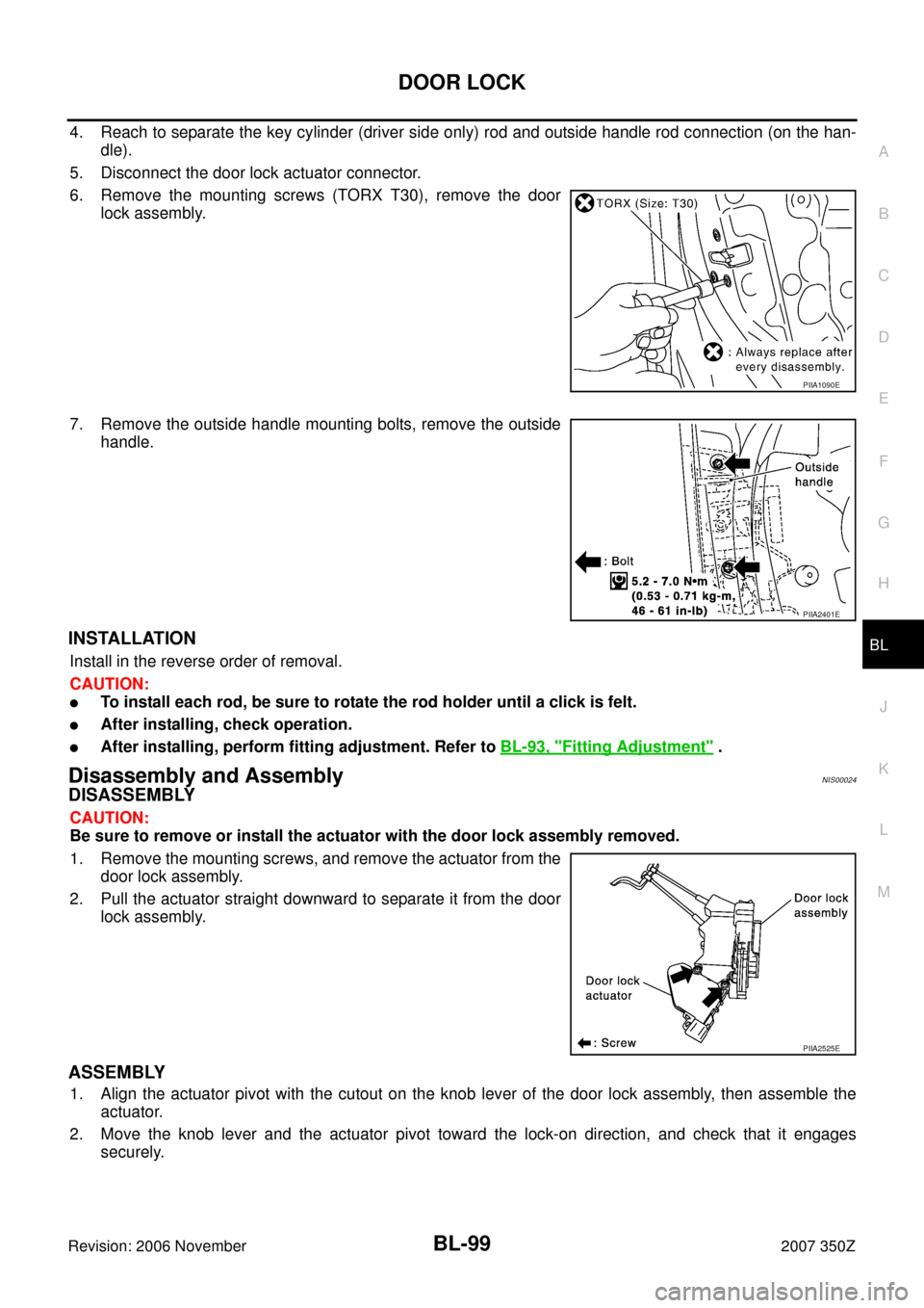
4. Reach to separate the key cylinder (driver side only) rod and outside handle rod connection (on the han-
dle).
5. Disconnect the door lock actuator connector.
6. Remove the mounting screws (TORX T30), remove the door
lock assembly.
7. Remove the outside handle mounting bolts, remove the outside
handle.
INSTALLATION
Install in the reverse order of removal.
CAUTION:
�To install each rod, be sure to rotate the rod holder until a click is felt.
�After installing, check operation.
�After installing, perform fitting adjustment. Refer to BL-93, "Fitting Adjustment" .
Disassembly and AssemblyNIS00024
DISASSEMBLY
CAUTION:
Be sure to remove or install the actuator with the door lock assembly removed.
1. Remove the mounting screws, and remove the actuator from the
door lock assembly.
2. Pull the actuator straight downward to separate it from the door
lock assembly.
ASSEMBLY
1. Align the actuator pivot with the cutout on the knob lever of the door lock assembly, then assemble the
actuator.
2. Move the knob lever and the actuator pivot toward the lock-on direction, and check that it engages
securely.
PIIA1090E
PIIA2401E
PIIA2525E
Page 100 of 260
BL-100
BACK DOOR
Revision: 2006 November2007 350Z
BACK DOORPFP:90100
Fitting AdjustmentNIS00025
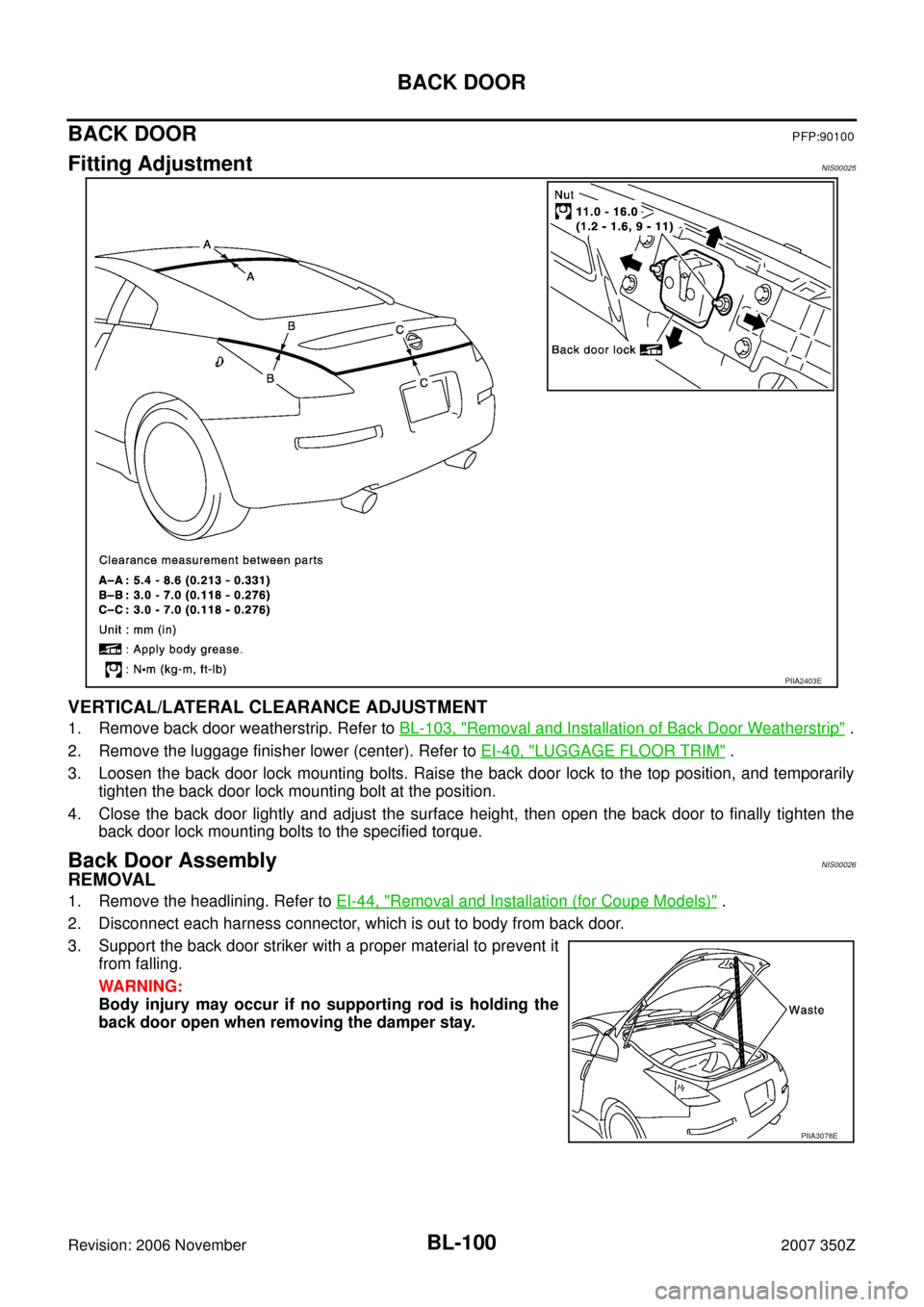
VERTICAL/LATERAL CLEARANCE ADJUSTMENT
1. Remove back door weatherstrip. Refer to BL-103, "Removal and Installation of Back Door Weatherstrip" .
2. Remove the luggage finisher lower (center). Refer to EI-40, "
LUGGAGE FLOOR TRIM" .
3. Loosen the back door lock mounting bolts. Raise the back door lock to the top position, and temporarily
tighten the back door lock mounting bolt at the position.
4. Close the back door lightly and adjust the surface height, then open the back door to finally tighten the
back door lock mounting bolts to the specified torque.
Back Door AssemblyNIS00026
REMOVAL
1. Remove the headlining. Refer to EI-44, "Removal and Installation (for Coupe Models)" .
2. Disconnect each harness connector, which is out to body from back door.
3. Support the back door striker with a proper material to prevent it
from falling.
WARNING:
Body injury may occur if no supporting rod is holding the
back door open when removing the damper stay.
PIIA2403E
PIIA3078E
Page 104 of 260
BL-104
BACK DOOR LOCK
Revision: 2006 November2007 350Z
BACK DOOR LOCKPFP:90504
Removal and Installation of Back Door Lock & Back Door Opener ActuatorNIS0002A
REMOVAL
1. Remove back door weatherstrip. Refer to BL-103, "Removal and Installation of Back Door Weatherstrip" .
2. Remove luggage finisher lower (center). Refer to EI-40, "
LUGGAGE FLOOR TRIM" .
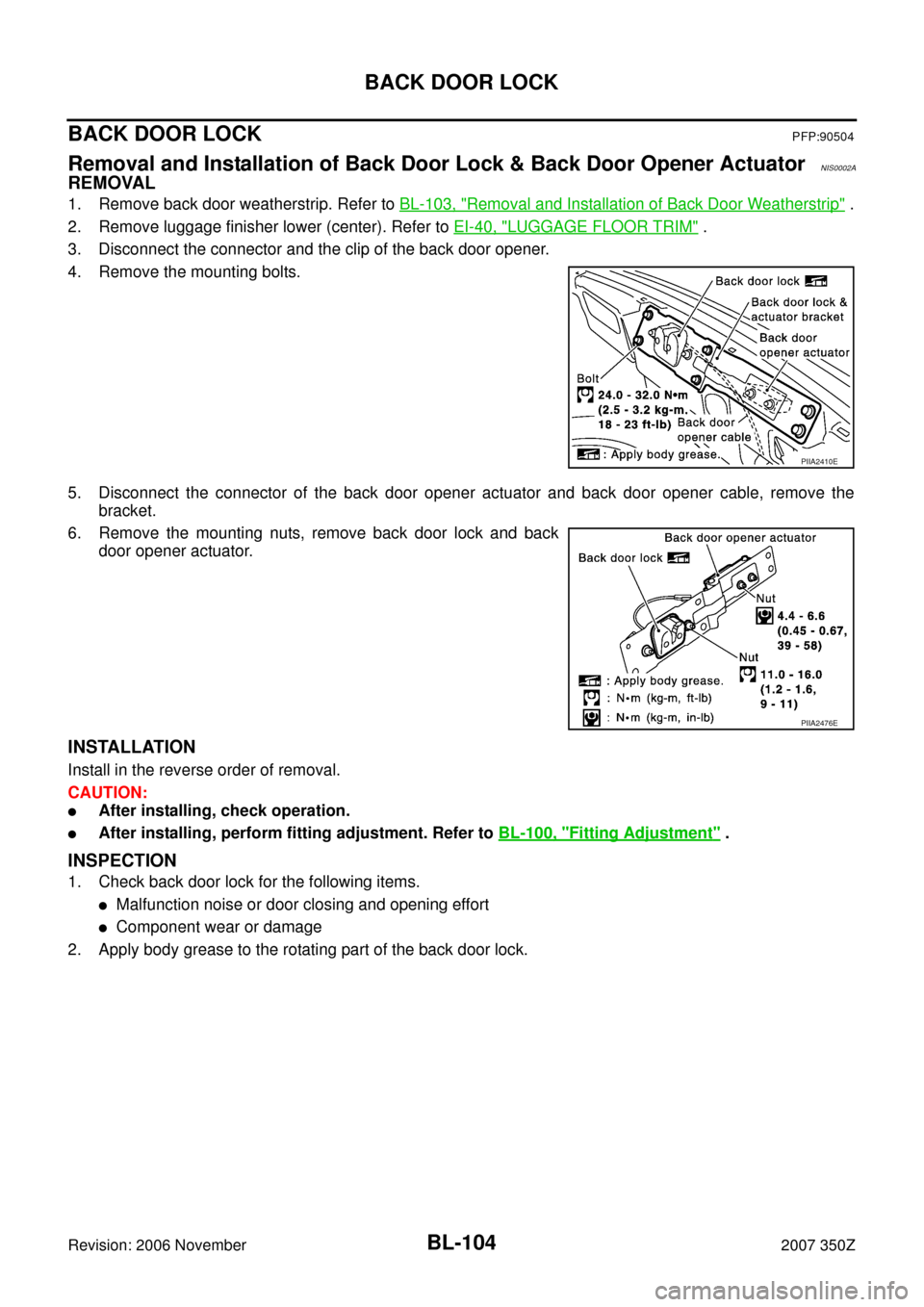
3. Disconnect the connector and the clip of the back door opener.
4. Remove the mounting bolts.
5. Disconnect the connector of the back door opener actuator and back door opener cable, remove the
bracket.
6. Remove the mounting nuts, remove back door lock and back
door opener actuator.
INSTALLATION
Install in the reverse order of removal.
CAUTION:
�After installing, check operation.
�After installing, perform fitting adjustment. Refer to BL-100, "Fitting Adjustment" .
INSPECTION
1. Check back door lock for the following items.
�Malfunction noise or door closing and opening effort
�Component wear or damage
2. Apply body grease to the rotating part of the back door lock.
PIIA2410E
PIIA2476E
Page 105 of 260
BACK DOOR LOCK
BL-105
C
D
E
F
G
H
J
K
L
MA
B
BL
Revision: 2006 November2007 350Z
Removal and Installation of Back Door Opener Switch (External)NIS0002B
REMOVAL
1. Remove rear bumper fascia assembly. Refer to EI-17, "Removal and Installation" .
2. Remove the mounting screws of the license plate bracket.
3. Remove the mounting screws and connector of the back door
opener switch.
INSTALLATION
1. Install in the reverse order of removal.
2. After installing, check the operation.
PIIA2477E
PIIA2478E
Page 106 of 260
BL-106
BACK DOOR LOCK
Revision: 2006 November2007 350Z
Removal and Installation of Back Door Emergency Opener CableNIS0002C
REMOVAL
1. Remove back door weather strip. Refer to BL-103, "Removal and Installation of Back Door Weatherstrip" .
2. Remove luggage finisher lower (center), luggage side finisher lower (LH), luggage side finisher upper
(LH), trunk side box, luggage floor carpet, strut cover rear, strut cover lower (center), and strut cover lower
(LH). Refer to EI-39, "
Removal and Installation (for Coupe Models)" .
3. Disconnect back door emergency opener cable from back door lock.
4. Disconnect back door emergency opener cable from back door emergency opener cable clamp, and then
remove back door emergency opener cable.
INSTALLATION
1. Install in the reverse order of removal.
2. After installing, check the operation.
1. Back door lock assembly 2. Back door emergency opener cable 3. hook
4. Clip
PIIB1491E
Page 107 of 260
TRUNK LID
BL-107
C
D
E
F
G
H
J
K
L
MA
B
BL
Revision: 2006 November2007 350Z
TRUNK LIDPFP:H4300
Fitting AdjustmentNIS0002D
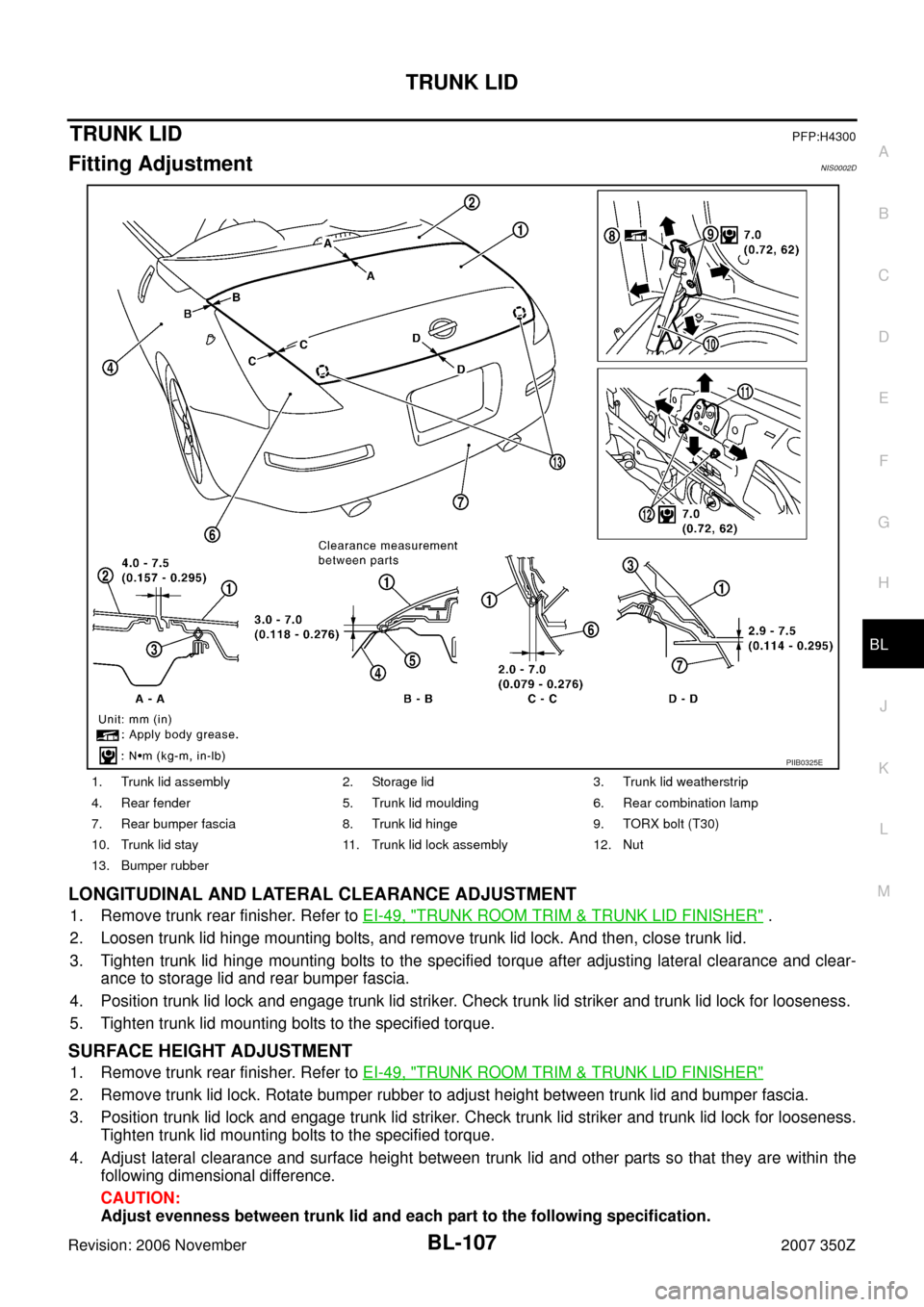
LONGITUDINAL AND LATERAL CLEARANCE ADJUSTMENT
1. Remove trunk rear finisher. Refer to EI-49, "TRUNK ROOM TRIM & TRUNK LID FINISHER" .
2. Loosen trunk lid hinge mounting bolts, and remove trunk lid lock. And then, close trunk lid.
3. Tighten trunk lid hinge mounting bolts to the specified torque after adjusting lateral clearance and clear-
ance to storage lid and rear bumper fascia.
4. Position trunk lid lock and engage trunk lid striker. Check trunk lid striker and trunk lid lock for looseness.
5. Tighten trunk lid mounting bolts to the specified torque.
SURFACE HEIGHT ADJUSTMENT
1. Remove trunk rear finisher. Refer to EI-49, "TRUNK ROOM TRIM & TRUNK LID FINISHER"
2. Remove trunk lid lock. Rotate bumper rubber to adjust height between trunk lid and bumper fascia.
3. Position trunk lid lock and engage trunk lid striker. Check trunk lid striker and trunk lid lock for looseness.
Tighten trunk lid mounting bolts to the specified torque.
4. Adjust lateral clearance and surface height between trunk lid and other parts so that they are within the
following dimensional difference.
CAUTION:
Adjust evenness between trunk lid and each part to the following specification.
1. Trunk lid assembly 2. Storage lid 3. Trunk lid weatherstrip
4. Rear fender 5. Trunk lid moulding 6. Rear combination lamp
7. Rear bumper fascia 8. Trunk lid hinge 9. TORX bolt (T30)
10. Trunk lid stay 11. Trunk lid lock assembly 12. Nut
13. Bumper rubber
PIIB0325E