Page 45 of 260
POWER DOOR LOCK SYSTEM
BL-45
C
D
E
F
G
H
J
K
L
MA
B
BL
Revision: 2006 November2007 350Z
Check Driver Side Door Lock Actuator NIS0000T
1. CHECK DOOR LOCK ACTUATOR SIGNAL
1. Turn ignition switch OFF.
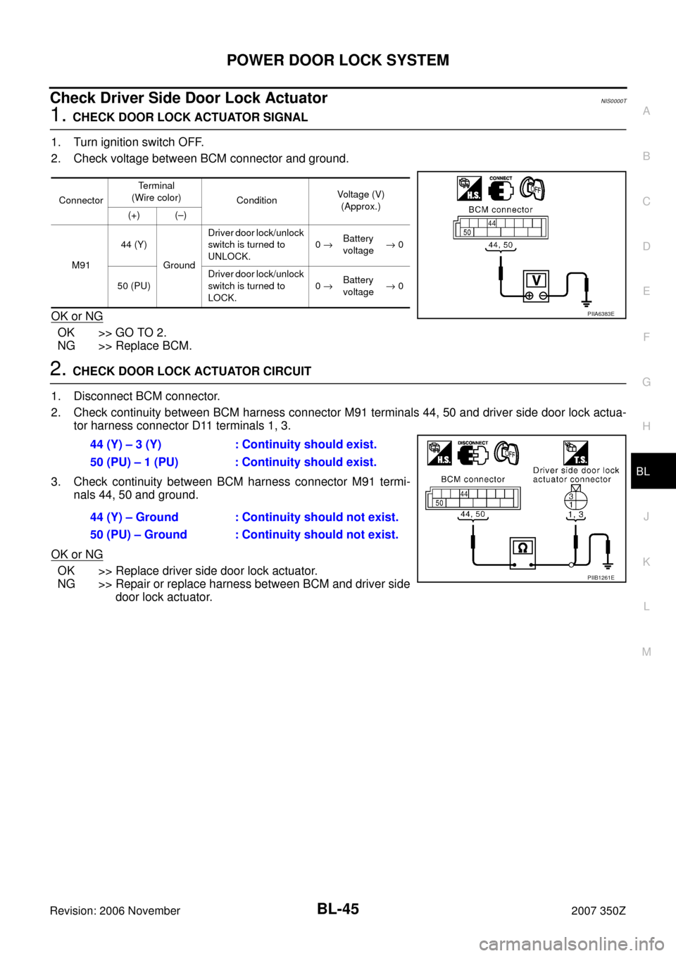
2. Check voltage between BCM connector and ground.
OK or NG
OK >> GO TO 2.
NG >> Replace BCM.
2. CHECK DOOR LOCK ACTUATOR CIRCUIT
1. Disconnect BCM connector.
2. Check continuity between BCM harness connector M91 terminals 44, 50 and driver side door lock actua-
tor harness connector D11 terminals 1, 3.
3. Check continuity between BCM harness connector M91 termi-
nals 44, 50 and ground.
OK or NG
OK >> Replace driver side door lock actuator.
NG >> Repair or replace harness between BCM and driver side
door lock actuator.
ConnectorTerminal
(Wire color)
ConditionVoltage (V)
(Approx.)
(+) (–)
M9144 (Y)
GroundDriver door lock/unlock
switch is turned to
UNLOCK.0 →Battery
voltage→ 0
50 (PU)Driver door lock/unlock
switch is turned to
LOCK.0 →Battery
voltage→ 0
PIIA6383E
44 (Y) – 3 (Y) : Continuity should exist.
50 (PU) – 1 (PU) : Continuity should exist.
44 (Y) – Ground : Continuity should not exist.
50 (PU) – Ground : Continuity should not exist.
PIIB1261E
Page 46 of 260
BL-46
POWER DOOR LOCK SYSTEM
Revision: 2006 November2007 350Z
Check Passenger Side Door Lock Actuator NIS0000U
1. CHECK DOOR LOCK ACTUATOR SIGNAL
1. Turn ignition switch OFF.
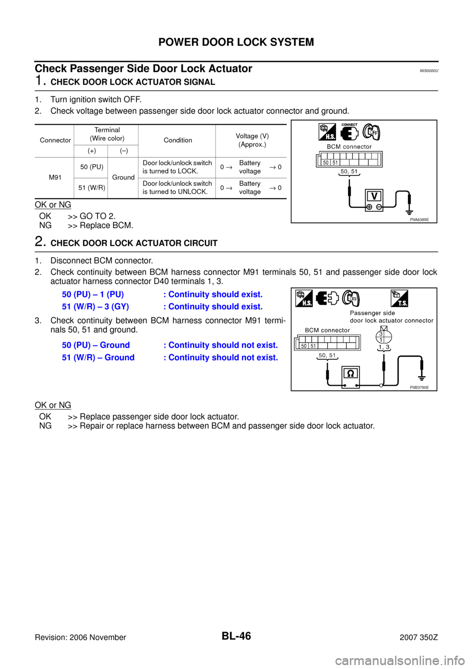
2. Check voltage between passenger side door lock actuator connector and ground.
OK or NG
OK >> GO TO 2.
NG >> Replace BCM.
2. CHECK DOOR LOCK ACTUATOR CIRCUIT
1. Disconnect BCM connector.
2. Check continuity between BCM harness connector M91 terminals 50, 51 and passenger side door lock
actuator harness connector D40 terminals 1, 3.
3. Check continuity between BCM harness connector M91 termi-
nals 50, 51 and ground.
OK or NG
OK >> Replace passenger side door lock actuator.
NG >> Repair or replace harness between BCM and passenger side door lock actuator.
ConnectorTerminal
(Wire color)
ConditionVoltage (V)
(Approx.)
(+) (–)
M9150 (PU)
GroundDoor lock/unlock switch
is turned to LOCK.0 →Battery
voltage→ 0
51 (W/R)Door lock/unlock switch
is turned to UNLOCK.0 →Battery
voltage→ 0
PIIA6385E
50 (PU) – 1 (PU) : Continuity should exist.
51 (W/R) – 3 (GY) : Continuity should exist.
50 (PU) – Ground : Continuity should not exist.
51 (W/R) – Ground : Continuity should not exist.
PIIB3790E
Page 47 of 260
POWER DOOR LOCK SYSTEM
BL-47
C
D
E
F
G
H
J
K
L
MA
B
BL
Revision: 2006 November2007 350Z
Check Door Key Cylinder Switch NIS0000V
1. CHECK DOOR KEY CYLINDER SWITCH INPUT SIGNAL
With CONSULT-III
�Check door key cylinder switch (“KEY CYL LK SW”) in “DATA MONITOR” mode with CONSULT-III.
�Check door key cylinder switch (“KEY CYL UN-SW”) in “DATA MONITOR” mode with CONSULT-III.
Without CONSULT-III
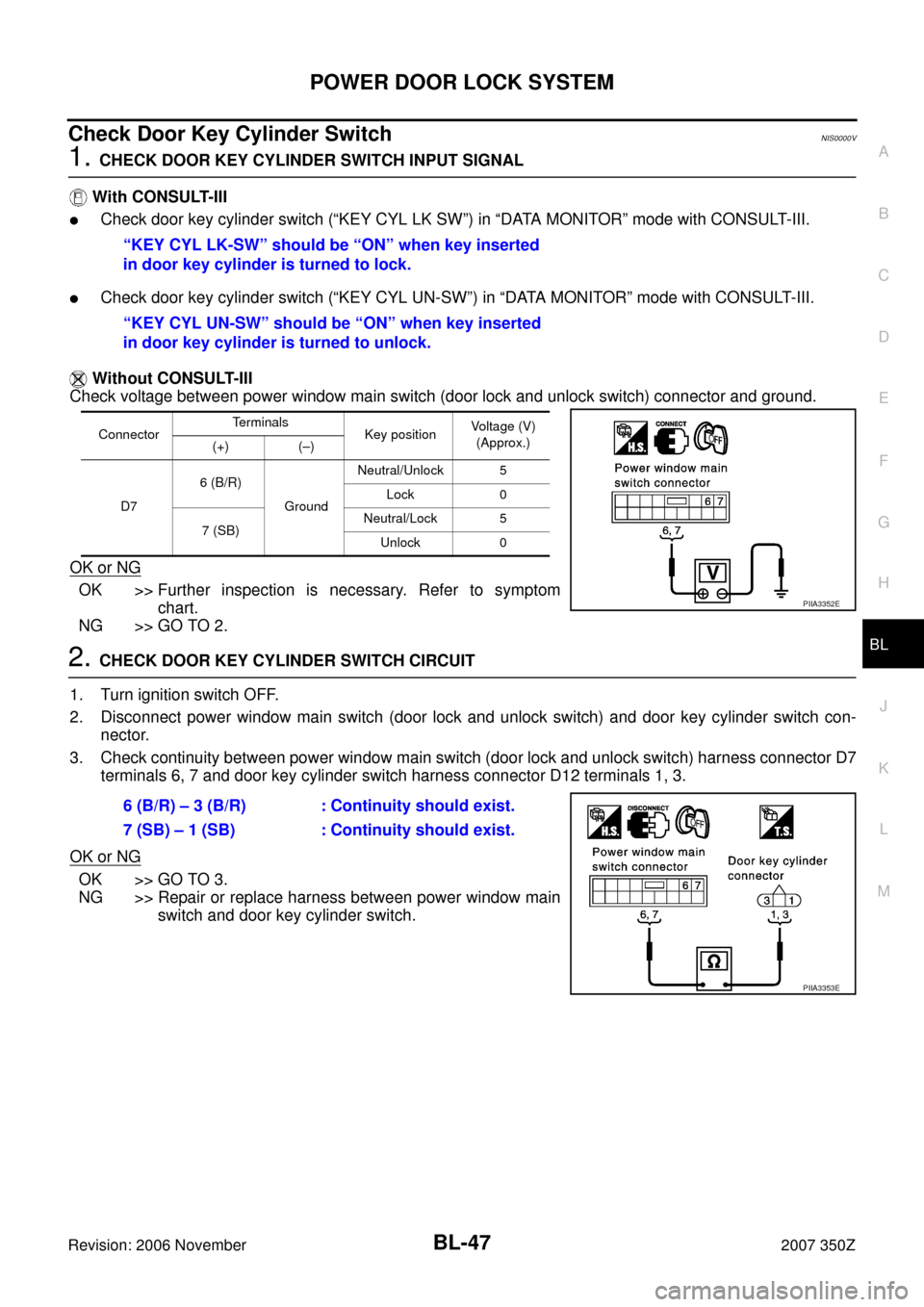
Check voltage between power window main switch (door lock and unlock switch) connector and ground.
OK or NG
OK >> Further inspection is necessary. Refer to symptom
chart.
NG >> GO TO 2.
2. CHECK DOOR KEY CYLINDER SWITCH CIRCUIT
1. Turn ignition switch OFF.
2. Disconnect power window main switch (door lock and unlock switch) and door key cylinder switch con-
nector.
3. Check continuity between power window main switch (door lock and unlock switch) harness connector D7
terminals 6, 7 and door key cylinder switch harness connector D12 terminals 1, 3.
OK or NG
OK >> GO TO 3.
NG >> Repair or replace harness between power window main
switch and door key cylinder switch. “KEY CYL LK-SW” should be “ON” when key inserted
in door key cylinder is turned to lock.
“KEY CYL UN-SW” should be “ON” when key inserted
in door key cylinder is turned to unlock.
ConnectorTe r m i n a l s
Key position Voltage (V)
(Approx.)
(+) (–)
D76 (B/R)
GroundNeutral/Unlock 5
Lock 0
7 (SB)Neutral/Lock 5
Unlock 0
PIIA3352E
6 (B/R) – 3 (B/R) : Continuity should exist.
7 (SB) – 1 (SB) : Continuity should exist.
PIIA3353E
Page 48 of 260
BL-48
POWER DOOR LOCK SYSTEM
Revision: 2006 November2007 350Z
3. CHECK DOOR KEY CYLINDER SWITCH GROUND CIRCUIT
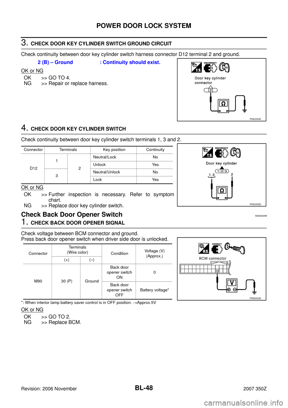
Check continuity between door key cylinder switch harness connector D12 terminal 2 and ground.
OK or NG
OK >> GO TO 4.
NG >> Repair or replace harness.
4. CHECK DOOR KEY CYLINDER SWITCH
Check continuity between door key cylinder switch terminals 1, 3 and 2.
OK or NG
OK >> Further inspection is necessary. Refer to symptom
chart.
NG >> Replace door key cylinder switch.
Check Back Door Opener Switch NIS0000W
1. CHECK BACK DOOR OPENER SIGNAL
Check voltage between BCM connector and ground.
Press back door opener switch when driver side door is unlocked.
*: When interior lamp battery saver control is in OFF position. →Approx.5V
OK or NG
OK >> GO TO 2.
NG >> Replace BCM.2 (B) – Ground : Continuity should exist.
PIIA3354E
Connector Terminals Key position Continuity
D121
2Neutral/Lock No
Unlock Yes
3Neutral/Unlock No
Lock Yes
PIIA3355E
ConnectorTerminals
(Wire color)
Condition Voltage (V)
(Approx.)
(+) (–)
M90 30 (P) GroundBack door
opener switch
ON0
Back door
opener switch
OFFBattery voltage*
PIIA9334E
Page 49 of 260
POWER DOOR LOCK SYSTEM
BL-49
C
D
E
F
G
H
J
K
L
MA
B
BL
Revision: 2006 November2007 350Z
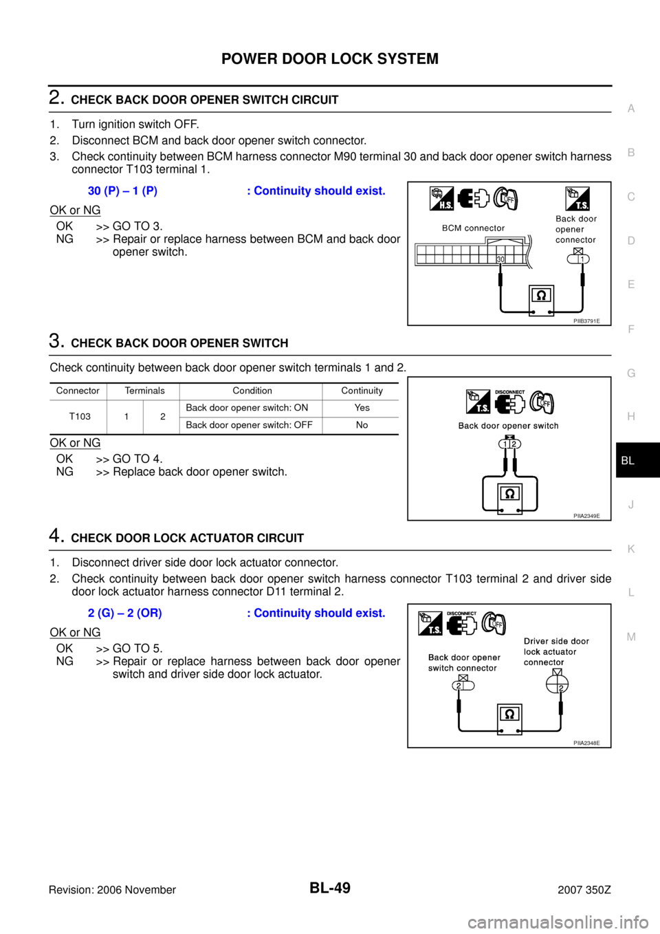
2. CHECK BACK DOOR OPENER SWITCH CIRCUIT
1. Turn ignition switch OFF.
2. Disconnect BCM and back door opener switch connector.
3. Check continuity between BCM harness connector M90 terminal 30 and back door opener switch harness
connector T103 terminal 1.
OK or NG
OK >> GO TO 3.
NG >> Repair or replace harness between BCM and back door
opener switch.
3. CHECK BACK DOOR OPENER SWITCH
Check continuity between back door opener switch terminals 1 and 2.
OK or NG
OK >> GO TO 4.
NG >> Replace back door opener switch.
4. CHECK DOOR LOCK ACTUATOR CIRCUIT
1. Disconnect driver side door lock actuator connector.
2. Check continuity between back door opener switch harness connector T103 terminal 2 and driver side
door lock actuator harness connector D11 terminal 2.
OK or NG
OK >> GO TO 5.
NG >> Repair or replace harness between back door opener
switch and driver side door lock actuator. 30 (P) – 1 (P) : Continuity should exist.
PIIB3791E
Connector Terminals Condition Continuity
T103 1 2Back door opener switch: ON Yes
Back door opener switch: OFF No
PIIA2349E
2 (G) – 2 (OR) : Continuity should exist.
PIIA2348E
Page 50 of 260
BL-50
POWER DOOR LOCK SYSTEM
Revision: 2006 November2007 350Z
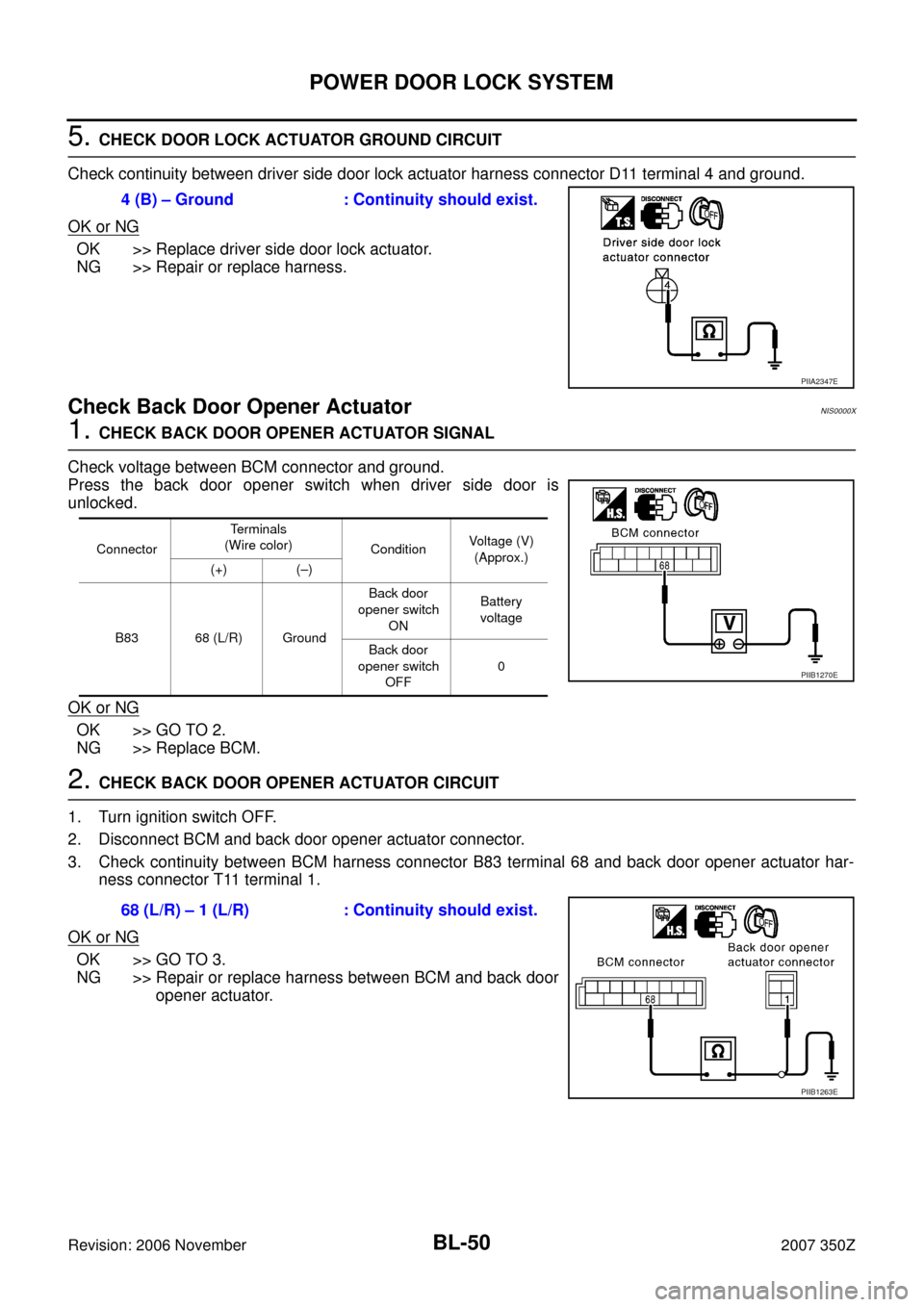
5. CHECK DOOR LOCK ACTUATOR GROUND CIRCUIT
Check continuity between driver side door lock actuator harness connector D11 terminal 4 and ground.
OK or NG
OK >> Replace driver side door lock actuator.
NG >> Repair or replace harness.
Check Back Door Opener Actuator NIS0000X
1. CHECK BACK DOOR OPENER ACTUATOR SIGNAL
Check voltage between BCM connector and ground.
Press the back door opener switch when driver side door is
unlocked.
OK or NG
OK >> GO TO 2.
NG >> Replace BCM.
2. CHECK BACK DOOR OPENER ACTUATOR CIRCUIT
1. Turn ignition switch OFF.
2. Disconnect BCM and back door opener actuator connector.
3. Check continuity between BCM harness connector B83 terminal 68 and back door opener actuator har-
ness connector T11 terminal 1.
OK or NG
OK >> GO TO 3.
NG >> Repair or replace harness between BCM and back door
opener actuator. 4 (B) – Ground : Continuity should exist.
PIIA2347E
ConnectorTerminals
(Wire color)
Condition Voltage (V)
(Approx.)
(+) (–)
B83 68 (L/R) GroundBack door
opener switch
ONBattery
voltage
Back door
opener switch
OFF0
PIIB1270E
68 (L/R) – 1 (L/R) : Continuity should exist.
PIIB1263E
Page 51 of 260
POWER DOOR LOCK SYSTEM
BL-51
C
D
E
F
G
H
J
K
L
MA
B
BL
Revision: 2006 November2007 350Z
3. CHECK BACK DOOR OPENER ACTUATOR GROUND CIRCUIT
Check continuity between back door opener actuator harness connector T11 terminal 2 and ground.
OK or NG
OK >> Replace back door opener actuator.
NG >> Repair or replace.2 (B) – Ground : Continuity should exist.
PIIA2354E
Page 52 of 260

BL-52
FUEL FILLER LID OPENER
Revision: 2006 November2007 350Z
FUEL FILLER LID OPENERPFP:78820
System Description/For RoadSterNIS0000Y
Power is supplied at all times
�through 40A fusible link (letter F , located in the fuse and fusible link box)
�to BCM terminal 55,
�through 10A fuse [No.18, located in the fuse block (J/B)]
�to BCM terminal 42.
When ignition switch ACC or ON position, power is supplied
�through 10A fuse [No. 6, located in the fuse block (J/B)]
�to BCM terminal 11.
Ground is supplied
�to BCM terminal 52
�through body grounds M30 and M66.
FUEL LID OPEN OPERATION
When fuel lid opener switch is ON (pushed), ground is supplied
�to BCM terminal 58
�through fuel lid opener switch terminals 1 and 2, and
�through body grounds M30 and M66.
And power is supplied
�to BCM terminal 70
�through fuel lid opener actuator terminals 1 and 2, and
�through body grounds B5, B6, and T14.
Then fuel lid opener actuator opens fuel lid.
FUEL LID OPENER CANCEL OPERATION
Fuel lid cannot open when vehicle condition is in arm or alarm phase.