Page 135 of 260
 SYSTEM
BL-135
C
D
E
F
G
H
J
K
L
MA
B
BL
Revision: 2006 November2007 350Z
Terminals and Reference Value for BCMNIS0002Y
Termi-
nal Wire
colorItemSignal
Input/
OutputC")
VEHICLE SECURITY (THEFT WARNING) SYSTEM
BL-135
C
D
E
F
G
H
J
K
L
MA
B
BL
Revision: 2006 November2007 350Z
Terminals and Reference Value for BCMNIS0002Y
Termi-
nal Wire
colorItemSignal
Input/
OutputConditionVoltage (V)
(Approx.)
11 LG Ignition switch (ACC) Input Ignition switch (ACC or ON) Battery voltage
12 P Passenger side door switch Input ON (Open) → OFF (Closed) 0 → 5
18 BRemote keyless entry receiver
(Ground)—— 0
19 YRemote keyless entry receiver
(Power supply)OutputKey is inserted is IGN key cyl-
inder0
All door closed
20 LRemote keyless entry receiver
(Signal)InputKey is inserted is IGN key cyl-
inder0
Stand-by
When remote keyless entry
receiver receives signal from
keyfob
22 YPower window switch
(Serial link)Input/
OutputDriver side door and passen-
ger side door are closed.
(Each door switch is OFF)
23 G/OR Security indicator lamp OutputGoes off → Illuminates (Every
2.4 seconds)Battery voltage → 0
39 L CAN-HInput/
Output——
40 P CAN-LInput/
Output——
42 GY Ignition switch (ON) Input Ignition switch (ON or START) Battery voltage
52 B Ground — — 0
55 R Power source (Fusible link) Input — Battery voltage
57 RTrunk room lamp switch
(For Roadster)Input
ON (Open) → OFF (Closed)
0 → Battery voltage*
1
58 R/W Back door switch (For Coupe) Input
62 L Driver side door switch Input ON (Open) → OFF (Closed) 0 → 5
OCC3881D
OCC3879D
OCC3880D
PIIA2344J
Page 137 of 260
 SYSTEM
BL-137
C
D
E
F
G
H
J
K
L
MA
B
BL
Revision: 2006 November2007 350Z
Terminals and Reference Value for IPDM E/RNIS0002Z
CONSULT-III Function (BCM)NIS00030
CONSULT-")
VEHICLE SECURITY (THEFT WARNING) SYSTEM
BL-137
C
D
E
F
G
H
J
K
L
MA
B
BL
Revision: 2006 November2007 350Z
Terminals and Reference Value for IPDM E/RNIS0002Z
CONSULT-III Function (BCM)NIS00030
CONSULT-III APPLICATION ITEM
Work Support
Data Monitor
Active Test
Terminal Wire
colorItemSignal
Input/
OutputConditionVoltage [V]
(Approx.)
38 B Ground — — 0
48 L CAN-HInput/
Output——
49 P CAN-LInput/
Output——
51 G/B Horn relay Output ON → OFF 0 → Battery voltage
60 B Ground — — 0
Test Item Description
SECURITY ALARM SET This mode is able to confirm and change security alarm ON-OFF setting.
THEFT ALM TRGThe switch which triggered vehicle security alarm is recorded. This mode is able to confirm and
erase the record of vehicle security alarm. The trigger data can be erased by touching “CLEAR”
on CONSULT-III screen.
Monitored Item Description
IGN ON SW Indicates [ON/OFF] condition of ignition switch.
ACC ON SW Indicates [ON/OFF] condition of ignition switch in ACC position.
KEY CYL LK SW Indicates [ON/OFF] condition of lock signal from key cylinder switch.
KEY CYL UN SW Indicates [ON/OFF] condition of unlock signal from key cylinder switch.
DOOR SW-DR Indicates [ON/OFF] condition of driver side door switch.
DOOR SW-AS Indicates [ON/OFF] condition of passenger side door switch.
BACK DOOR SW Indicates [ON/OFF] condition of back door switch.
TRUNK OPNR SW Indicates [ON/OFF] condition of trunk room lamp switch. (Roadster models)
TRUNK OPN MNTRThis is displayed even when it is not equipped.
Indicates [ON/OFF] condition of trunk lid opener switch. (Roadster models)
TRUNK KEY SW This is displayed even when it is not equipped.
DOOR SW-RR This is displayed even when it is not equipped.
HOOD SW Indicates [ON/OFF] condition of hood switch.
LOCK SW DR/ASIndicates [ON/OFF] condition of lock signal from driver and passenger side door lock/unlock
switch.
UNLK SW DR/ASIndicates [ON/OFF] condition of unlock signal from driver and passenger side door lock/unlock
switch.
LK BUTTON/SIG Indicates [ON/OFF] condition of lock signal from key fob.
UN BUTTON/SIG Indicates [ON/OFF] condition of unlock signal from key fob.
TRUNK BTN/SIGIndicate [ON/OFF] condition of back door open signal from key fob (for Coupe).
Indicates [ON/OFF] condition of trunk open signal from key fob (for Roadster).
Test Item Description
THEFT INDThis test is able to check security indicator lamp operation. The lamp will be turned on when “ON”
on CONSULT-III screen is touched.
Page 139 of 260
VEHICLE SECURITY (THEFT WARNING) SYSTEM
BL-139
C
D
E
F
G
H
J
K
L
MA
B
BL
Revision: 2006 November2007 350Z
�“REMOTE KEYLESS ENTRY” Diagnosis; refer to BL-75, "Work Flow" .
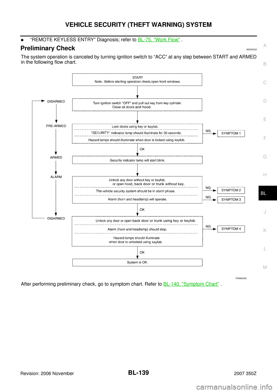
Preliminary CheckNIS00033
The system operation is canceled by turning ignition switch to “ACC” at any step between START and ARMED
in the following flow chart.
After performing preliminary check, go to symptom chart. Refer to BL-140, "
Symptom Chart" .
PIIA8954E
Page 140 of 260
 SYSTEM
Revision: 2006 November2007 350Z
Symptom ChartNIS00034
*1: Make sure the system is in the armed phase.PROCEDURE
Diagnostic procedure Reference page
SYMPT")
BL-140
VEHICLE SECURITY (THEFT WARNING) SYSTEM
Revision: 2006 November2007 350Z
Symptom ChartNIS00034
*1: Make sure the system is in the armed phase.PROCEDURE
Diagnostic procedure Reference page
SYMPTOM
1Vehicle secu-
rity system
cannot be set
by ····Door switchDiagnostic Procedure 1 (Check door, hood, back door switch or
trunk room lamp switch)BL-141
Lock/unlock switch Diagnostic Procedure 6 (Check door lock/unlock switch)BL-149
Door outside key Diagnostic Procedure 3 (Check door key cylinder switch)BL-147
Key fob Check remote keyless entry system function.BL-61
BCM If the above systems are “OK”, replace BCM.BCS-17
Security indicator does not turn “ON”.Diagnostic Procedure 2 (Check security indicator lamp)BL-146If the above systems are “OK”, replace BCM.BCS-17
2*1 Vehicle
security sys-
tem does not
alarm when
····Any door is opened.Diagnostic Procedure 1 (Check door, hood and trunk room lamp
switch)BL-141
If the above systems are “OK”, replace BCM.BCS-17
3Vehicle secu-
rity alarm
does not acti-
vate.Horn alarmDiagnostic Procedure 4 (Check vehicle security horn alarm)BL-148If the above systems are “OK”, replace BCM.BCS-17
Headlamp alarmDiagnostic Procedure 5 (Check vehicle security headlamp alarm)BL-148If the above systems are “OK”, replace BCM.BCS-17
4Vehicle secu-
rity system
cannot be
canceled by
····Door outside key Diagnostic Procedure 3 (Check door key cylinder switch)BL-147Key fobCheck remote keyless entry system function.BL-61If the above systems are “OK”, replace BCM.BCS-17
Page 147 of 260
VEHICLE SECURITY (THEFT WARNING) SYSTEM
BL-147
C
D
E
F
G
H
J
K
L
MA
B
BL
Revision: 2006 November2007 350Z
Diagnostic Procedure 3NIS00037
CHECK DOOR KEY CYLINDER SWITCH
1. CHECK DOOR KEY CYLINDER SWITCH DRIVER SIDE OPERATION
Do doors lock/unlock when using the key?
YES or NO
YES >> Door key cylinder switch operation is OK.
NO >> Check door key cylinder switch circuit. Refer to BL-47, "
Check Door Key Cylinder Switch" .
Page 150 of 260
BL-150
NVIS (NISSAN VEHICLE IMMOBILIZER SYSTEM-NATS)
Revision: 2006 November2007 350Z
NVIS (NISSAN VEHICLE IMMOBILIZER SYSTEM-NATS)PFP:25386
Component Parts and Harness Connector LocationNIS0003B
NOTE:
If customer reports a “No start” condition, request ALL KEYS to be brought to an NISSAN dealer in
case of a NVIS (NATS) malfunction.
PIIB7461E
Page 151 of 260

BL-151
C
D
E
F
G
H
J
K
L
MA
B
BL
Revision: 2006 November2007 350Z
System DescriptionNIS0003C
NVIS (Nissan Vehicle Immobilizer System-NATS) has the followi")
NVIS (NISSAN VEHICLE IMMOBILIZER SYSTEM-NATS)
BL-151
C
D
E
F
G
H
J
K
L
MA
B
BL
Revision: 2006 November2007 350Z
System DescriptionNIS0003C
NVIS (Nissan Vehicle Immobilizer System-NATS) has the following immobilizer functions:
�Since only NVIS (NATS) ignition keys, whose ID Nos. have been registered into the ECM and BCM, allow
the engine to run, a vehicle operation without a key registered in NVIS (NATS) is prevented by NVIS
(NATS).
That is to say, NVIS (NATS) will immobilize the engine if someone tries to start it without the registered
key of NVIS (NATS).
�All of the originally supplied ignition key IDs (except for card plate key) have been registered in NVIS
(NATS).
If requested by the vehicle owner, a maximum of five key IDs can be registered into the NVIS (NATS)
components.
�The security indicator blinks when the ignition switch is in “OFF” or “ACC” position. Therefore, NVIS
(NATS) warns outsiders that the vehicle is equipped with the anti-theft system.
�When NVIS (NATS) detects trouble, the security indicator lamp lights up while ignition key is in the “ON”
position.
�NVIS (NATS) trouble diagnoses, system initialization and additional registration of other NVIS (NATS)
ignition key IDs must be carried out using CONSULT-III hardware and CONSULT-III NVIS (NATS) soft-
ware.
When NVIS (NATS) initialization has been completed, the ID of the inserted ignition key is automatically
registered in NVIS (NATS). Then, if necessary, additional registration of other NVIS (NATS) ignition key
IDs can be carried out.
Regarding the procedures of NVIS (NATS) initialization and NVIS (NATS) ignition key ID registration, refer
to CONSULT-III Operation Manual NATS-IVIS/NVIS.
�When servicing a malfunction of the NVIS (NATS) (indicated by lighting up of Security Indicator
Lamp) or registering another NVIS (NATS) ignition key ID No., it may be necessary to re-register
original key identification. Therefore, be sure to receive ALL KEYS from vehicle owner.
Page 152 of 260

Revision: 2006 November2007 350Z
System CompositionNIS0003D
The immobilizer function of the NVIS (NATS) consists of the following:
�NATS ignition k")
BL-152
NVIS (NISSAN VEHICLE IMMOBILIZER SYSTEM-NATS)
Revision: 2006 November2007 350Z
System CompositionNIS0003D
The immobilizer function of the NVIS (NATS) consists of the following:
�NATS ignition key
�NATS antenna amp. located in the ignition key cylinder
�BCM
�Engine control module (ECM)
�Security indicator
NOTE:
The communication between ECM and BCM uses the CAN communication system.
ECM Re-communicating FunctionNIS0003E
Performing following procedure can automatically perform re-communication of ECM and BCM, but only
when the ECM has been replaced with a new one (*1).
*1: New one means a virgin ECM which has never been energized on-board.
(In this step, initialization procedure by CONSULT-III is not necessary)
NOTE:
�When registering new Key IDs or replacing the ECM other than brand new, refer to CONSULT-III
Operation Manual NATS-IVIS/NVIS.
�If multiple keys are attached to the key holder, separate them before work.
�Distinguish keys with unregistered key ID from those with registered ID.
1. Install ECM.
2. Using a registered key (*2), turn ignition switch to “ON”.
*2: To perform this step, use the key (except for card plate key) that has been used before performing
ECM replacement.
3. Maintain ignition switch in “ON” position for at least 5 seconds.
4. Turn ignition switch to “OFF”.
5. Start engine.
If engine can be started, procedure is completed.
If engine cannot be started, refer to CONSULT-III Operation Manual NATS-IVIS/NVIS and initialize control
unit.
PIIA1121E
 SYSTEM
BL-147
C
D
E
F
G
H
J
K
L
MA
B
BL
Revision: 2006 November2007 350Z
Diagnostic Procedure 3NIS00037
CHECK DOOR KEY CYLINDER SWITCH
1. CHECK DOOR KEY CYLINDER SWIT")

Revision: 2006 November2007 350Z
NVIS (NISSAN VEHICLE IMMOBILIZER SYSTEM-NATS)PFP:25386
Component Parts and Harness Connector LocationNIS0003B
NOTE")