Page 90 of 260
BL-90
REMOTE KEYLESS ENTRY SYSTEM
Revision: 2006 November2007 350Z
KEY FOB ID SETUP WITHOUT CONSULT-III
PIIA2839E
Page 91 of 260

REMOTE KEYLESS ENTRY SYSTEM
BL-91
C
D
E
F
G
H
J
K
L
MA
B
BL
Revision: 2006 November2007 350Z
NOTE:
�If a key fob is lost, the ID code of the lost key fob must be erased to prevent unauthorized use. A specific
ID code can be erased with CONSULT-III. However, when the ID code of a lost key fob is not known, all
controller ID codes should be erased. After all ID codes are erased, the ID codes of all remaining and/or
new key fobs must be re-registered.
To erase all ID codes in memory, register one ID code (key fob) five times. After all ID codes are erased,
the ID codes of all remaining and/or new key fobs must be re-registered.
�When registering an additional key fob, the existing ID codes in memory may or may not be erased. If five
ID codes are stored in memory, when an additional code is registered, only the oldest code is erased. If
less than five ID codes are stored in memory, when an additional ID code is registered, the new ID code is
added and no ID codes are erased.
�If you need to activate more than two additional new key fobs, repeat the procedure “Additional ID code
entry” for each new key fob.
�Entry of maximum five ID codes is allowed. When more than five ID codes are entered, the oldest ID code
will be erased.
�Even if same ID code that is already in the memory is input, the same ID code can be entered. The code
is counted as an additional code.
Key Fob Battery ReplacementNIS0001V
SEL411Y
Page 92 of 260
BL-92
REMOTE KEYLESS ENTRY SYSTEM
Revision: 2006 November2007 350Z
Removal and Installation of Remote Keyless Entry ReceiverNIS0001W
REMOVAL
1. Remove the instrument passenger panel lower. Refer to IP-13, "(L) Instrument Passenger Panel Lower" .
2. Remove the screw and remote keyless entry receiver connector.
3. Remove the remote keyless entry receiver.
INSTALLATION
Install in the reverse order of removal.
PIIB3798E
Page 118 of 260

(Approx.)
18 BRemote keyless")
BL-118
TRUNK LID OPENER
Revision: 2006 November2007 350Z
Terminals and Reference Value for BCMNIS0002P
Te r -
minalWire
colorItemSignal input/
outputConditionVoltage (V)
(Approx.)
18 BRemote keyless entry
receiver (Ground)—— 0
19 YRemote keyless entry
receiver (Power supply)OutputKey is inserted in IGN key cylinder 0
All door closed
20 LRemote keyless entry
receiver (Signal)InputKey is inserted in IGN key cylinder 0
Waiting
(All door closed)
When signal is received
(All door closed)
30 P Trunk lid opener switch InputTrunk lid opener
cancel switch is
ONTrunk lid opener
switch is ON0
Trunk lid opener
switch is OFF5
Driver side door is
lockedTrunk lid opener
cancel switch is
OFF5
39 L CAN – H Input/Output — —
40 P CAN – L Input/Output — —
42 GY Ignition switch (ON) Input Ignition switch ON or START position Battery voltage
52 B Ground — — 0
55 RPower source (Fusible
link)Input — Battery voltage
68 L/RTrunk lid opener release
output signalOutput Closed (OFF) → Opened (ON) 0 → Battery voltage
OCC3881D
OCC3879D
OCC3880D
Page 128 of 260
 SYSTEM
Revision: 2006 November2007 350Z
When the key is used to unlock a door, BCM terminal 22 receives signal
�from terminal 12 of the power window main switch")
BL-128
VEHICLE SECURITY (THEFT WARNING) SYSTEM
Revision: 2006 November2007 350Z
When the key is used to unlock a door, BCM terminal 22 receives signal
�from terminal 12 of the power window main switch (door lock and unlock switch).
When the BCM receives either above signal or unlock signal from key fob, the vehicle security system is deac-
tivated. (Disarmed phase)
PANIC ALARM OPERATION
Remote keyless entry system may or may not operate vehicle security system (horn and headlamps) as
required.
When the panic alarm button on the keyfob is triggered, ground is supplied intermittently to both headlamp
relay and horn relay.
When both headlamp relay (with built-in IPDM E/R) and horn relay are energized and then power is supplied
to headlamps (high beam and low beam) and horns (HIGH and LOW).
The headlamp flashes and the horn sounds intermittently.
The alarm automatically turns off after 25 seconds or when BCM receives any signal from key fob.
CAN Communication System DescriptionNIS0002U
CAN (Controller Area Network) is a serial communication line for real time application. It is an on-vehicle mul-
tiplex communication line with high data communication speed and excellent error detection ability. Many elec-
tronic control units are equipped onto a vehicle, and each control unit shares information and links with other
control units during operation (not independent). In CAN communication, control units are connected with 2
communication lines (CAN H line, CAN L line) allowing a high rate of information transmission with less wiring.
Each control unit transmits/receives data but selectively reads required data only.
CAN Communication UnitNIS0002V
Refer to LAN-4, "CAN Communication System" .
Page 135 of 260
 SYSTEM
BL-135
C
D
E
F
G
H
J
K
L
MA
B
BL
Revision: 2006 November2007 350Z
Terminals and Reference Value for BCMNIS0002Y
Termi-
nal Wire
colorItemSignal
Input/
OutputC")
VEHICLE SECURITY (THEFT WARNING) SYSTEM
BL-135
C
D
E
F
G
H
J
K
L
MA
B
BL
Revision: 2006 November2007 350Z
Terminals and Reference Value for BCMNIS0002Y
Termi-
nal Wire
colorItemSignal
Input/
OutputConditionVoltage (V)
(Approx.)
11 LG Ignition switch (ACC) Input Ignition switch (ACC or ON) Battery voltage
12 P Passenger side door switch Input ON (Open) → OFF (Closed) 0 → 5
18 BRemote keyless entry receiver
(Ground)—— 0
19 YRemote keyless entry receiver
(Power supply)OutputKey is inserted is IGN key cyl-
inder0
All door closed
20 LRemote keyless entry receiver
(Signal)InputKey is inserted is IGN key cyl-
inder0
Stand-by
When remote keyless entry
receiver receives signal from
keyfob
22 YPower window switch
(Serial link)Input/
OutputDriver side door and passen-
ger side door are closed.
(Each door switch is OFF)
23 G/OR Security indicator lamp OutputGoes off → Illuminates (Every
2.4 seconds)Battery voltage → 0
39 L CAN-HInput/
Output——
40 P CAN-LInput/
Output——
42 GY Ignition switch (ON) Input Ignition switch (ON or START) Battery voltage
52 B Ground — — 0
55 R Power source (Fusible link) Input — Battery voltage
57 RTrunk room lamp switch
(For Roadster)Input
ON (Open) → OFF (Closed)
0 → Battery voltage*
1
58 R/W Back door switch (For Coupe) Input
62 L Driver side door switch Input ON (Open) → OFF (Closed) 0 → 5
OCC3881D
OCC3879D
OCC3880D
PIIA2344J
Page 139 of 260
VEHICLE SECURITY (THEFT WARNING) SYSTEM
BL-139
C
D
E
F
G
H
J
K
L
MA
B
BL
Revision: 2006 November2007 350Z
�“REMOTE KEYLESS ENTRY” Diagnosis; refer to BL-75, "Work Flow" .
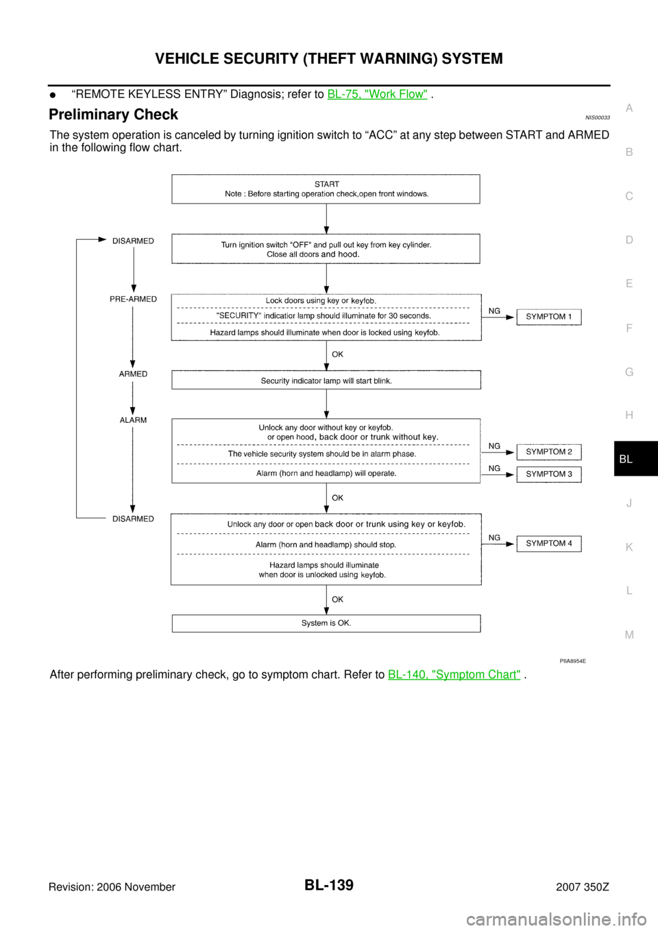
Preliminary CheckNIS00033
The system operation is canceled by turning ignition switch to “ACC” at any step between START and ARMED
in the following flow chart.
After performing preliminary check, go to symptom chart. Refer to BL-140, "
Symptom Chart" .
PIIA8954E
Page 140 of 260
 SYSTEM
Revision: 2006 November2007 350Z
Symptom ChartNIS00034
*1: Make sure the system is in the armed phase.PROCEDURE
Diagnostic procedure Reference page
SYMPT")
BL-140
VEHICLE SECURITY (THEFT WARNING) SYSTEM
Revision: 2006 November2007 350Z
Symptom ChartNIS00034
*1: Make sure the system is in the armed phase.PROCEDURE
Diagnostic procedure Reference page
SYMPTOM
1Vehicle secu-
rity system
cannot be set
by ····Door switchDiagnostic Procedure 1 (Check door, hood, back door switch or
trunk room lamp switch)BL-141
Lock/unlock switch Diagnostic Procedure 6 (Check door lock/unlock switch)BL-149
Door outside key Diagnostic Procedure 3 (Check door key cylinder switch)BL-147
Key fob Check remote keyless entry system function.BL-61
BCM If the above systems are “OK”, replace BCM.BCS-17
Security indicator does not turn “ON”.Diagnostic Procedure 2 (Check security indicator lamp)BL-146If the above systems are “OK”, replace BCM.BCS-17
2*1 Vehicle
security sys-
tem does not
alarm when
····Any door is opened.Diagnostic Procedure 1 (Check door, hood and trunk room lamp
switch)BL-141
If the above systems are “OK”, replace BCM.BCS-17
3Vehicle secu-
rity alarm
does not acti-
vate.Horn alarmDiagnostic Procedure 4 (Check vehicle security horn alarm)BL-148If the above systems are “OK”, replace BCM.BCS-17
Headlamp alarmDiagnostic Procedure 5 (Check vehicle security headlamp alarm)BL-148If the above systems are “OK”, replace BCM.BCS-17
4Vehicle secu-
rity system
cannot be
canceled by
····Door outside key Diagnostic Procedure 3 (Check door key cylinder switch)BL-147Key fobCheck remote keyless entry system function.BL-61If the above systems are “OK”, replace BCM.BCS-17