Page 110 of 312
AT-110
DTC P0720 VEHICLE SPEED SENSOR A/T (REVOLUTION SENSOR)
Revision: 2006 November2007 350Z
Wiring Diagram — AT — VSSA/TNCS0003A
TCWM0249E
Page 111 of 312
DTC P0720 VEHICLE SPEED SENSOR A/T (REVOLUTION SENSOR)
AT-111
D
E
F
G
H
I
J
K
L
MA
B
AT
Revision: 2006 November2007 350Z
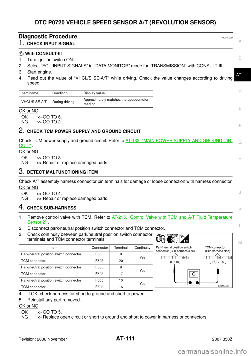
Diagnostic ProcedureNCS0003B
1. CHECK INPUT SIGNAL
With CONSULT-III
1. Turn ignition switch ON.
2. Select “ECU INPUT SIGNALS” in “DATA MONITOR” mode for “TRANSMISSION” with CONSULT-III.
3. Start engine.
4. Read out the value of “VHCL/S SE-A/T” while driving. Check the value changes according to driving
speed.
OK or NG
OK >> GO TO 6.
NG >> GO TO 2.
2. CHECK TCM POWER SUPPLY AND GROUND CIRCUIT
Check TCM power supply and ground circuit. Refer to AT- 1 6 2 , "
MAIN POWER SUPPLY AND GROUND CIR-
CUIT" .
OK or NG
OK >> GO TO 3.
NG >> Repair or replace damaged parts.
3. DETECT MALFUNCTIONING ITEM
Check A/T assembly harness connector pin terminals for damage or loose connection with harness connector.
OK or NG
OK >> GO TO 4.
NG >> Repair or replace damaged parts.
4. CHECK SUB-HARNESS
1. Remove control valve with TCM. Refer to AT- 2 1 5 , "
Control Valve with TCM and A/T Fluid Temperature
Sensor 2" .
2. Disconnect park/neutral position switch connector and TCM connector.
3. Check continuity between park/neutral position switch connector
terminals and TCM connector terminals.
4. If OK, check harness for short to ground and short to power.
5. Reinstall any part removed.
OK or NG
OK >> GO TO 5.
NG >> Replace open circuit or short to ground and short to power in harness or connectors.
Item name Condition Display value
VHCL/S SE-A/T During drivingApproximately matches the speedometer
reading.
Item Connector Terminal Continuity
Park/neutral position switch connector F505 8
Ye s
TCM connector F503 20
Park/neutral position switch connector F505 9
Ye s
TCM connector F503 17
Park/neutral position switch connector F505 10
Ye s
TCM connector F503 16
SCIA5458E
Page 112 of 312
AT-112
DTC P0720 VEHICLE SPEED SENSOR A/T (REVOLUTION SENSOR)
Revision: 2006 November2007 350Z
5. REPLACE THE REVOLUTION SENSOR AND CHECK DTC
1. Replace revolution sensor. Refer to AT- 2 3 5 , "
Revolution Sensor" .
2. Perform AT- 1 0 8 , "
DTC Confirmation Procedure" .
OK or NG
OK >>INSPECTION END
NG >> Replace control valve with TCM. Refer to AT- 2 1 5 , "
Control Valve with TCM and A/T Fluid Temper-
ature Sensor 2" .
6. CHECK DTC
Perform AT- 1 0 8 , "
DTC Confirmation Procedure" .
OK or NG
OK >>INSPECTION END
NG >> GO TO 2.
Page 114 of 312
AT-114
DTC P0725 ENGINE SPEED SIGNAL
Revision: 2006 November2007 350Z
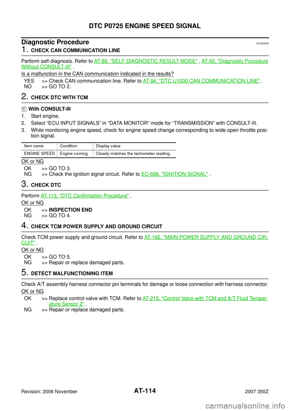
Diagnostic ProcedureNCS0003H
1. CHECK CAN COMMUNICATION LINE
Perform self-diagnosis. Refer to AT- 8 6 , "
SELF-DIAGNOSTIC RESULT MODE" , AT- 9 2 , "Diagnostic Procedure
Without CONSULT-III" .
Is a malfunction in the CAN communication indicated in the results?
YES >> Check CAN communication line. Refer to AT- 9 4 , "DTC U1000 CAN COMMUNICATION LINE" .
NO >> GO TO 2.
2. CHECK DTC WITH TCM
With CONSULT-III
1. Start engine.
2. Select “ECU INPUT SIGNALS” in “DATA MONITOR” mode for “TRANSMISSION” with CONSULT-III.
3. While monitoring engine speed, check for engine speed change corresponding to wide-open throttle posi-
tion signal.
OK or NG
OK >> GO TO 3.
NG >> Check the ignition signal circuit. Refer to EC-698, "
IGNITION SIGNAL" .
3. CHECK DTC
Perform AT- 11 3 , "
DTC Confirmation Procedure" .
OK or NG
OK >>INSPECTION END
NG >> GO TO 4.
4. CHECK TCM POWER SUPPLY AND GROUND CIRCUIT
Check TCM power supply and ground circuit. Refer to AT- 1 6 2 , "
MAIN POWER SUPPLY AND GROUND CIR-
CUIT" .
OK or NG
OK >> GO TO 5.
NG >> Repair or replace damaged parts.
5. DETECT MALFUNCTIONING ITEM
Check A/T assembly harness connector pin terminals for damage or loose connection with harness connector.
OK or NG
OK >> Replace control valve with TCM. Refer to AT- 2 1 5 , "Control Valve with TCM and A/T Fluid Temper-
ature Sensor 2" .
NG >> Repair or replace damaged parts.
Item name Condition Display value
ENGINE SPEED Engine running Closely matches the tachometer reading.
Page 116 of 312
AT-116
DTC P0731 A/T 1ST GEAR FUNCTION
Revision: 2006 November2007 350Z
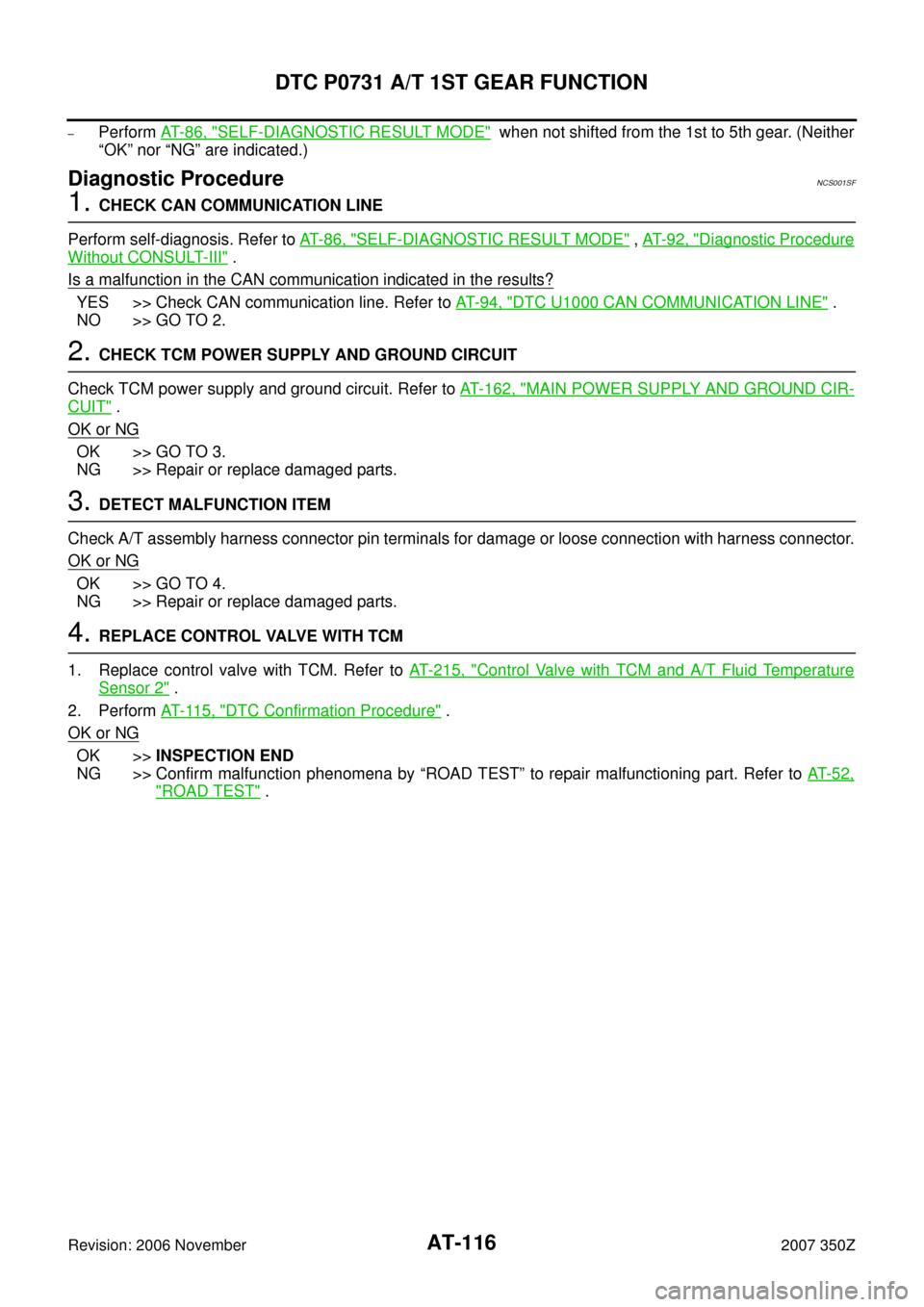
–Perform AT- 8 6 , "SELF-DIAGNOSTIC RESULT MODE" when not shifted from the 1st to 5th gear. (Neither
“OK” nor “NG” are indicated.)
Diagnostic ProcedureNCS001SF
1. CHECK CAN COMMUNICATION LINE
Perform self-diagnosis. Refer to AT- 8 6 , "
SELF-DIAGNOSTIC RESULT MODE" , AT- 9 2 , "Diagnostic Procedure
Without CONSULT-III" .
Is a malfunction in the CAN communication indicated in the results?
YES >> Check CAN communication line. Refer to AT- 9 4 , "DTC U1000 CAN COMMUNICATION LINE" .
NO >> GO TO 2.
2. CHECK TCM POWER SUPPLY AND GROUND CIRCUIT
Check TCM power supply and ground circuit. Refer to AT- 1 6 2 , "
MAIN POWER SUPPLY AND GROUND CIR-
CUIT" .
OK or NG
OK >> GO TO 3.
NG >> Repair or replace damaged parts.
3. DETECT MALFUNCTION ITEM
Check A/T assembly harness connector pin terminals for damage or loose connection with harness connector.
OK or NG
OK >> GO TO 4.
NG >> Repair or replace damaged parts.
4. REPLACE CONTROL VALVE WITH TCM
1. Replace control valve with TCM. Refer to AT- 2 1 5 , "
Control Valve with TCM and A/T Fluid Temperature
Sensor 2" .
2. Perform AT- 11 5 , "
DTC Confirmation Procedure" .
OK or NG
OK >>INSPECTION END
NG >> Confirm malfunction phenomena by “ROAD TEST” to repair malfunctioning part. Refer to AT- 5 2 ,
"ROAD TEST" .
Page 118 of 312
AT-118
DTC P0732 A/T 2ND GEAR FUNCTION
Revision: 2006 November2007 350Z
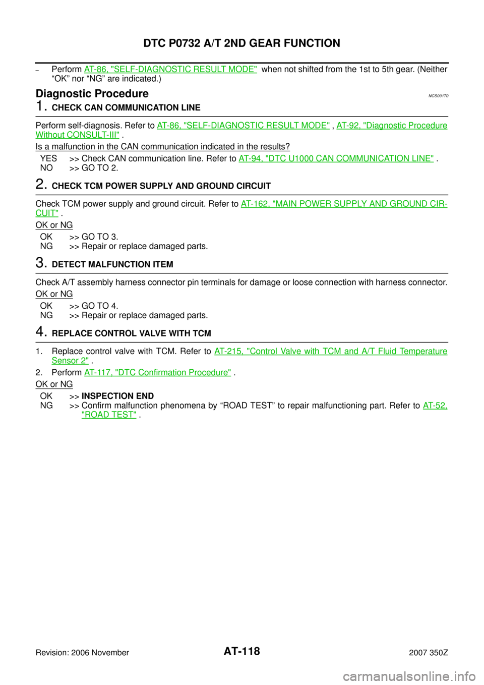
–Perform AT- 8 6 , "SELF-DIAGNOSTIC RESULT MODE" when not shifted from the 1st to 5th gear. (Neither
“OK” nor “NG” are indicated.)
Diagnostic ProcedureNCS001T0
1. CHECK CAN COMMUNICATION LINE
Perform self-diagnosis. Refer to AT- 8 6 , "
SELF-DIAGNOSTIC RESULT MODE" , AT- 9 2 , "Diagnostic Procedure
Without CONSULT-III" .
Is a malfunction in the CAN communication indicated in the results?
YES >> Check CAN communication line. Refer to AT- 9 4 , "DTC U1000 CAN COMMUNICATION LINE" .
NO >> GO TO 2.
2. CHECK TCM POWER SUPPLY AND GROUND CIRCUIT
Check TCM power supply and ground circuit. Refer to AT- 1 6 2 , "
MAIN POWER SUPPLY AND GROUND CIR-
CUIT" .
OK or NG
OK >> GO TO 3.
NG >> Repair or replace damaged parts.
3. DETECT MALFUNCTION ITEM
Check A/T assembly harness connector pin terminals for damage or loose connection with harness connector.
OK or NG
OK >> GO TO 4.
NG >> Repair or replace damaged parts.
4. REPLACE CONTROL VALVE WITH TCM
1. Replace control valve with TCM. Refer to AT- 2 1 5 , "
Control Valve with TCM and A/T Fluid Temperature
Sensor 2" .
2. Perform AT- 11 7 , "
DTC Confirmation Procedure" .
OK or NG
OK >>INSPECTION END
NG >> Confirm malfunction phenomena by “ROAD TEST” to repair malfunctioning part. Refer to AT- 5 2 ,
"ROAD TEST" .
Page 120 of 312
AT-120
DTC P0733 A/T 3RD GEAR FUNCTION
Revision: 2006 November2007 350Z
–Perform AT- 8 6 , "SELF-DIAGNOSTIC RESULT MODE" when not shifted from the 1st to 5th gear. (Neither
“OK” nor “NG” are indicated.)
Diagnostic ProcedureNCS001T1
1. CHECK CAN COMMUNICATION LINE
Perform self-diagnosis. Refer to AT- 8 6 , "
SELF-DIAGNOSTIC RESULT MODE" , AT- 9 2 , "Diagnostic Procedure
Without CONSULT-III" .
Is a malfunction in the CAN communication indicated in the results?
YES >> Check CAN communication line. Refer to AT- 9 4 , "DTC U1000 CAN COMMUNICATION LINE" .
NO >> GO TO 2.
2. CHECK TCM POWER SUPPLY AND GROUND CIRCUIT
Check TCM power supply and ground circuit. Refer to AT- 1 6 2 , "
MAIN POWER SUPPLY AND GROUND CIR-
CUIT" .
OK or NG
OK >> GO TO 3.
NG >> Repair or replace damaged parts.
3. DETECT MALFUNCTION ITEM
Check A/T assembly harness connector pin terminals for damage or loose connection with harness connector.
OK or NG
OK >> GO TO 4.
NG >> Repair or replace damaged parts.
4. REPLACE CONTROL VALVE WITH TCM
1. Replace control valve with TCM. Refer to AT- 2 1 5 , "
Control Valve with TCM and A/T Fluid Temperature
Sensor 2" .
2. Perform AT- 11 9 , "
DTC Confirmation Procedure" .
OK or NG
OK >>INSPECTION END
NG >> Confirm malfunction phenomena by “ROAD TEST” to repair malfunctioning part. Refer to AT- 5 2 ,
"ROAD TEST" .
Page 122 of 312
AT-122
DTC P0734 A/T 4TH GEAR FUNCTION
Revision: 2006 November2007 350Z
–Perform AT- 8 6 , "SELF-DIAGNOSTIC RESULT MODE" when not shifted from the 1st to 5th gear. (Neither
“OK” nor “NG” are indicated.)
Diagnostic ProcedureNCS001T2
1. CHECK CAN COMMUNICATION LINE
Perform self-diagnosis. Refer to AT- 8 6 , "
SELF-DIAGNOSTIC RESULT MODE" , AT- 9 2 , "Diagnostic Procedure
Without CONSULT-III" .
Is a malfunction in the CAN communication indicated in the results?
YES >> Check CAN communication line. Refer to AT- 9 4 , "DTC U1000 CAN COMMUNICATION LINE" .
NO >> GO TO 2.
2. CHECK TCM POWER SUPPLY AND GROUND CIRCUIT
Check TCM power supply and ground circuit. Refer to AT- 1 6 2 , "
MAIN POWER SUPPLY AND GROUND CIR-
CUIT" .
OK or NG
OK >> GO TO 3.
NG >> Repair or replace damaged parts.
3. DETECT MALFUNCTION ITEM
Check A/T assembly harness connector pin terminals for damage or loose connection with harness connector.
OK or NG
OK >> GO TO 4.
NG >> Repair or replace damaged parts.
4. REPLACE CONTROL VALVE WITH TCM
1. Replace control valve with TCM. Refer to AT- 2 1 5 , "
Control Valve with TCM and A/T Fluid Temperature
Sensor 2" .
2. Perform AT- 1 2 1 , "
DTC Confirmation Procedure" .
OK or NG
OK >>INSPECTION END
NG >> Confirm malfunction phenomena by “ROAD TEST” to repair malfunctioning part. Refer to AT- 5 2 ,
"ROAD TEST" .