A/T SHIFT LOCK SYSTEM
AT-211
D
E
F
G
H
I
J
K
L
MA
B
AT
Revision: 2006 November2007 350Z
7. DETECT MALFUNCTIONING ITEM
Check the following.
�Harness for short or open between ignition switch and shift lock relay E19 terminal 5.
�Harness for short or open between shift lock relay E19 terminal 3 and A/T device harness connector M47
terminal 1.
�10 A fuse [No. 12, located in the fuse block (J/B)].
�Ignition switch (Refer to PG-4, "POWER SUPPLY ROUTING CIRCUIT" ).
�Shift lock relay.
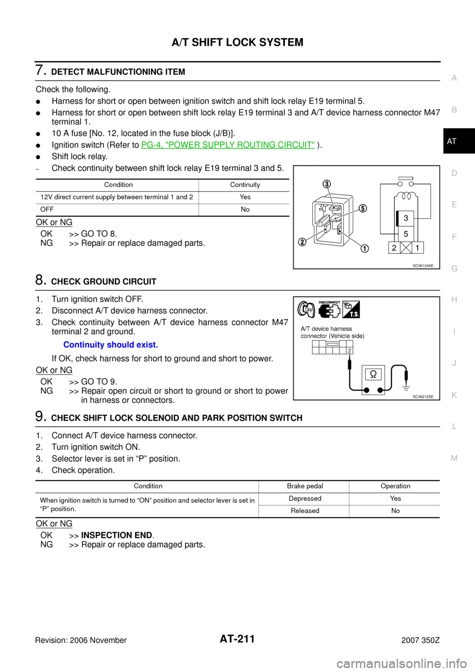
–Check continuity between shift lock relay E19 terminal 3 and 5.
OK or NG
OK >> GO TO 8.
NG >> Repair or replace damaged parts.
8. CHECK GROUND CIRCUIT
1. Turn ignition switch OFF.
2. Disconnect A/T device harness connector.
3. Check continuity between A/T device harness connector M47
terminal 2 and ground.
If OK, check harness for short to ground and short to power.
OK or NG
OK >> GO TO 9.
NG >> Repair open circuit or short to ground or short to power
in harness or connectors.
9. CHECK SHIFT LOCK SOLENOID AND PARK POSITION SWITCH
1. Connect A/T device harness connector.
2. Turn ignition switch ON.
3. Selector lever is set in “P” position.
4. Check operation.
OK or NG
OK >>INSPECTION END.
NG >> Repair or replace damaged parts.
Condition Continuity
12V direct current supply between terminal 1 and 2 Yes
OFF No
SCIA1245E
Continuity should exist.
SCIA2125E
Condition Brake pedal Operation
When ignition switch is turned to “ON” position and selector lever is set in
“P” position.Depressed Yes
Released No