Page 142 of 1449
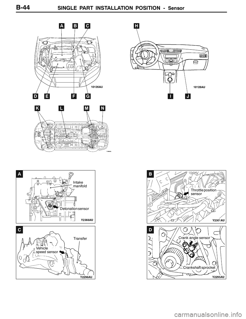
SINGLE PART INSTALLATION POSITION -Sensor
A
Intake
manifold
Detonation sensor
B
Throttle position
sensor
C
Vehicle
speed sensor
Transfer
D
Crank angle sensor
Crankshaft sprocket
B-44
ABC
DEFG
H
IJ
KLMN
Page 408 of 1449
11A-2
ENGINE
CONTENTS
GENERAL INFORMATION 3..................
SERVICE SPECIFICATIONS 4.................
SEALANTS 4................................
SPECIAL TOOLS 5...........................
ON-VEHICLE SERVICE 7.....................
Drive Belt Tension Check 7.....................
Auto-tensioner Check 7.........................
Ignition Timing Check 9.........................
Idle Speed Check 9............................
Idle Mixture Check 10..........................
Compression Pressure Check 11................Manifold Vacuum Check 12.....................
Lash Adjuster Check 12........................
CRANKSHAFT PULLEY 15....................
CAMSHAFT AND CAMSHAFT OIL
SEAL 16.....................................
OIL PAN 23..................................
CRANKSHAFT OIL SEAL 26..................
CYLINDER HEAD GASKET 28................
TIMING BELT AND TIMING BELT B 34.......
ENGINE ASSEMBLY 43.......................
Page 411 of 1449
ENGINE -Special Tools11A-5
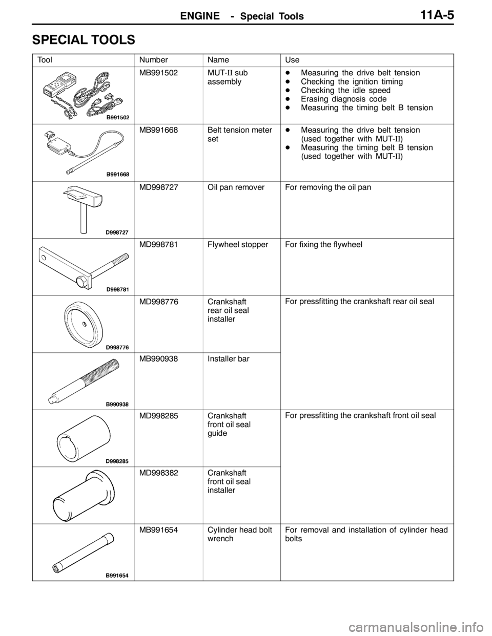
SPECIAL TOOLS
ToolNumberNameUse
MB991502MUT-IIsub
assemblyDMeasuring the drive belt tension
DChecking the ignition timing
DChecking the idle speed
DErasing diagnosis code
DMeasuring the timing belt B tension
MB991668Belt tension meter
setDMeasuring the drive belt tension
(used together with MUT-II)
DMeasuring the timing belt B tension
(used together with MUT-II)
MD998727Oil pan removerFor removing the oil pan
MD998781Flywheel stopperFor fixing the flywheel
MD998776Crankshaft
rear oil seal
installerFor pressfitting the crankshaft rear oil seal
MB990938Installer bar
MD998285Crankshaft
front oil seal
guideFor pressfitting the crankshaft front oil seal
MD998382Crankshaft
front oil seal
installer
MB991654Cylinder head bolt
wrenchFor removal and installation of cylinder head
bolts
Page 412 of 1449
ENGINE -Special Tools11A-6
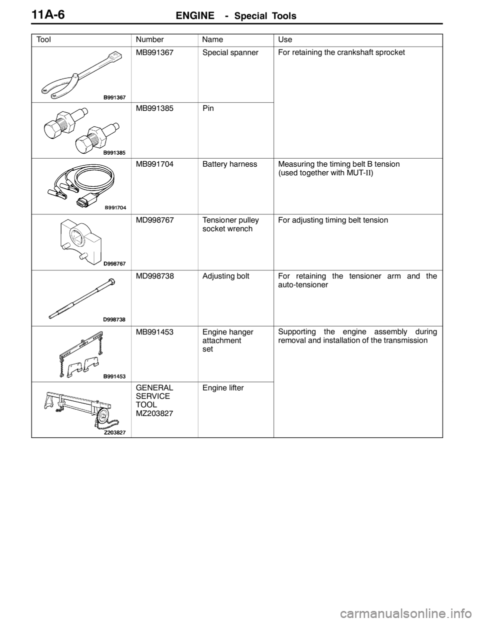
Tool UseName Number
MB991367Special spannerFor retaining the crankshaft sprocket
MB991385Pin
MB991704Battery harnessMeasuring the timing belt B tension
(used together with MUT-II)
MD998767Tensioner pulley
socket wrenchFor adjusting timing belt tension
MD998738Adjusting boltFor retaining the tensioner arm and the
auto-tensioner
MB991453Engine hanger
attachment
setSupporting the engine assembly during
removal and installation of the transmission
GENERAL
SERVICE
TOOL
MZ203827Engine lifter
Page 413 of 1449

ENGINE -On-vehicle Service11A-7
ON-VEHICLE SERVICE
DRIVE BELT TENSION CHECK
1. Check that the indicator marking of the auto-tensioner
is within the range as shown in the illustration A of the
tensioner bracket.
Caution
Inspection must be carried out after turning the
crankshaft clockwise for more than once.
2. If the marking is outside the range as shown in the
illustration A, replace the drive belt.
NOTE
Due to the adoption of the auto-tensioner, no adjustment
for belt tension is required.
AUTO-TENSIONER CHECK
1. Check that the driver belt stays within the width of the
pulley of the auto-tensioner after turning off the engine
at idle.
2. Remove the drive belt.(Refer to P.11C-15.)
3. Use the 12.7sq. spinner handle and etc. to check that
the auto-tensioner is not stuck by turning it in both
directions.
4. If there is any abnormality in the above - mentioned 1
or 3, replace the auto-tensioner.
5. Install the drive belt.(Refer to P.11C-15.)
To determine whether the auto-tensioner is acceptable can
be done by checking the drive belt tension.
1. Use the following procedure to check the drive belt tension.
(1) Connect the special tool (MB991668) to the MUT-II.
(2) Connect the MUT-IIto the diagnosis connector.
Caution
Connection and disconnection of the MUT-IImust
be carried out after turning the ignition switch
to the “LOCK” (OFF) position.
(3) Turn the ignition switch to the “ON” position and select
“Belt Tension Measurement” from the menu screen.
Indicator
marking
A
Page 419 of 1449

ENGINE -On-vehicle Service11A-13
(2) If there is a problem with the lash adjusters, the noise
will almost never disappear, even if the engine has
been run at idle to let it warm up.
The only case where the noise might disappear is
if the oil in the engine has not been looked after
properly and oil sludge has caused the lash adjusters
to stick.
1. Start the engine.
2. Check that the noise occurs immediately after the engine
is started, and that the noise changes in accordance
with changes in the engine speed.
If the noise does not occur immediately after the engine
is started, or if it does not change in accordance with
the engine speed, the problem is not being caused by
the lash adjusters, so check for some other cause of
the problem. Moreover, if the noise does not change in
accordance with the engine speed, the cause of the
problem is probably not with the engine. (In these cases,
the lash adjusters are normal.)
3. While the engine is idling, check that the noise level does
not change when the engine load is varied.
If the noise level changes, the cause of the noise is
probably parts striking because of worn crankshaft
bearings or connecting rod bearings. (In such cases, the
lash adjusters are normal.)
4. After the engine has warmed up, run it at idle and check
if any noise can be heard.
If the noise has become smaller or disappeared, oil sludge
could make the lash adjusters stick. Clean the lash
adjusters. (Refer to the Engine Workshop Manual.) If not
improved, go to step 5.
5. Bleed air from the lash adjusters.
6. If the noise has not disappeared even after the air
bleeding, clean the lash adjusters.
(Refer to GROUP 11B - Rocker Arms and Camshaft.)
NOTE
(1) If the vehicle is parked on a slope for a long period
of time, the amount of oil inside the lash adjuster
will decrease, and air may get into the high pressure
chamber when starting the engine.
(2) After parking the vehicle for long periods, the oil drains
out of the oil passage, and it takes time for the oil
to be supplied to the lash adjuster, so air can get
into the high pressure chamber.
(3) If either of the above situations occur, the abnormal
noise can be eliminated by bleeding the air from inside
the lash adjusters.
Page 420 of 1449

ENGINE -On-vehicle Service11A-14
1. Check the engine oil and replenish or replace the oil
if necessary.
NOTE
(1) If there is a only small amount of oil, air will be drawn
in through the oil screen and will get into the oil
passage.
(2) If the amount of oil is greater than normal, then the
oil will being mixed by the crankshaft and a large
amount of air may get mixed into the oil.
(3) If the oil is degenerated, air and oil will not separate
easily in oil, and the amount of air mixed into the
oil will increase.
(4) If the air which has been mixed in with the oil due
to any of the above reasons gets into the high pressure
chamber of the lash adjuster, the air inside the high
pressure chamber will be compressed when the valve
is open and the lash adjuster will over-compress,
resulting in abnormal noise when the valve closes.
This is the same effect as if the valve clearance is
adjusted to be too large by mistake. If the air inside
the lash adjusters is then released, the operation
of the lash adjusters will return to normal.
2. Run the engine at idle for 1 - 3 minutes to let it warm
up.
3. With no load on the engine, repeat the drive pattern shown
in the illustration at left and check if the abnormal noise
disappears. (The noise should normally disappear after
10 - 30 repetitions, but if there is no change in the noise
level after 30 repetitions or more, the problem is probably
not due to air inside the lash adjusters.)
4. After the noise has disappeared, repeat the drive pattern
shown in the illustration at left a further 5 times.
5. Run the engine at idle for 1 - 3 minutes and check that
the noise has disappeared.
Good
High-pressure chamber
Gradually open the
throttle valve.
Drive pattern for air bleeding
Close the throttle
valve.
Approx.
3,000 r/min
15
seconds15
seconds
Idle speed
Once
Page 421 of 1449
ENGINE -Crankshaft Pulley11A-15
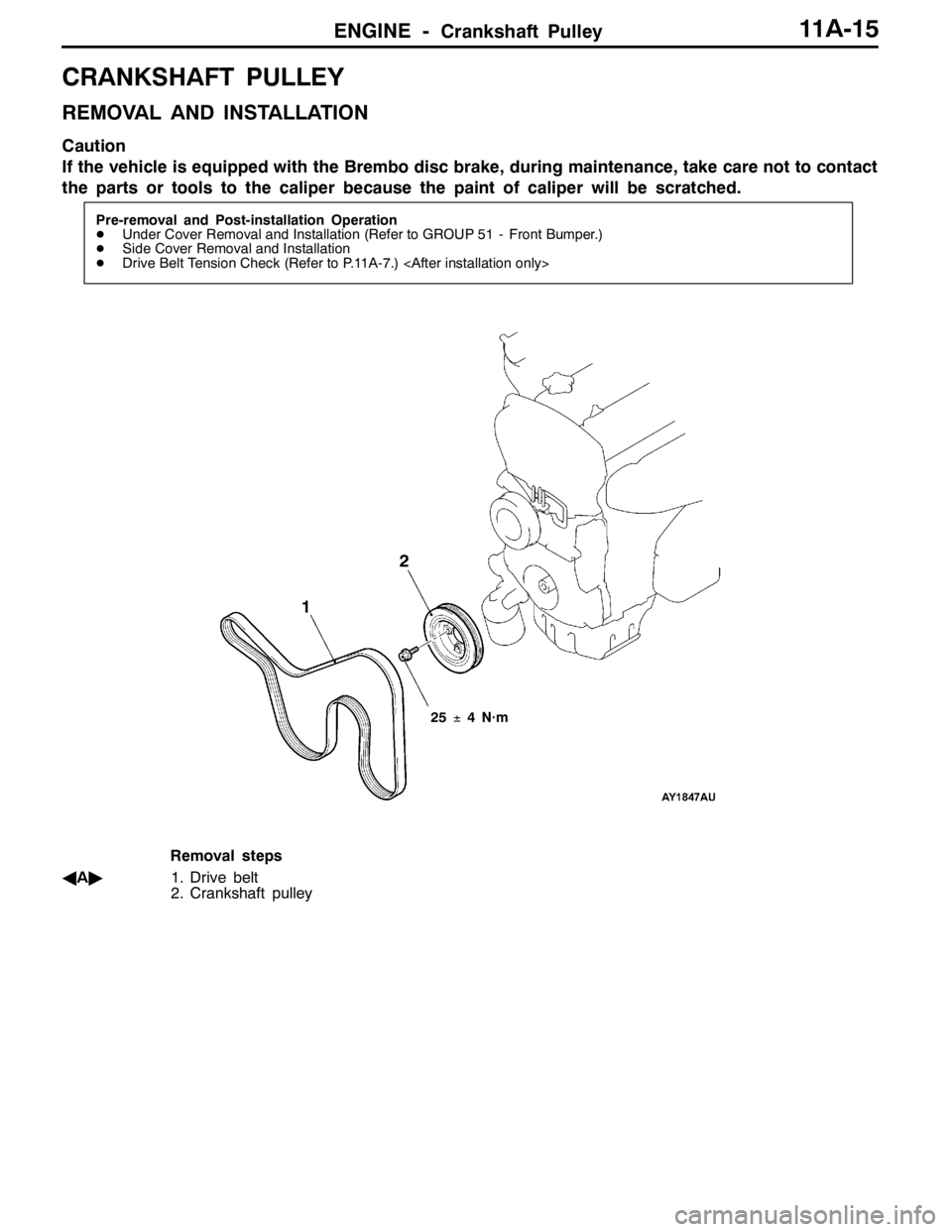
CRANKSHAFT PULLEY
REMOVAL AND INSTALLATION
Caution
If the vehicle is equipped with the Brembo disc brake, during maintenance, take care not to contact
the parts or tools to the caliper because the paint of caliper will be scratched.
Pre-removal and Post-installation Operation
DUnder Cover Removal and Installation (Refer to GROUP 51 - Front Bumper.)
DSide Cover Removal and Installation
DDrive Belt Tension Check (Refer to P.11A-7.)
25±4 N·m
12
Removal steps
AA"1. Drive belt
2. Crankshaft pulley