2007 MITSUBISHI LANCER EVOLUTION coolant temperature
[x] Cancel search: coolant temperaturePage 697 of 1449
![MITSUBISHI LANCER EVOLUTION 2007 Service Repair Manual ENGINE COOLING -On-vehicle Service14-9
5. Connect the special tool (MB991658) to the harness side
of the engine coolant temperature sensor connector.
6. Connect the special tool [MB991791(APS)] to the MITSUBISHI LANCER EVOLUTION 2007 Service Repair Manual ENGINE COOLING -On-vehicle Service14-9
5. Connect the special tool (MB991658) to the harness side
of the engine coolant temperature sensor connector.
6. Connect the special tool [MB991791(APS)] to the](/manual-img/19/57084/w960_57084-696.png)
ENGINE COOLING -On-vehicle Service14-9
5. Connect the special tool (MB991658) to the harness side
of the engine coolant temperature sensor connector.
6. Connect the special tool [MB991791(APS)] to the special
tool (MB991658).
7. Start the engine and let it run at idle.
NOTE
Since the resistance value of the special tool (APS)
indicates a low engine coolant temperature, engine speed
increases.
8. When the lever of the special tool (APS) is turned to
the end, check that the engine speed decreases and
the radiator fan motor rotates.
9. When the lever of the special tool (APS) is turned to
the reverse direction, check that the voltage between
terminals of the radiator fan motor connector gradually
decreases from the battery voltage to 0 V.
10. If inoperable, replace the radiator fan controller.
(Refer to P.14-15.)
11. Install the center under cover.
(Refer to GROUP 51 - Front Bumper.)
12. Connect the engine coolant temperature sensor
connector.
1. Remove the center under cover.
(Refer to GROUP 51 - Front Bumper.)
2. Insert the special tool at the back of the radiator fan
motor connector.
3. Connect the special tool to the circuit tester.
4. Start the engine and run it at idle.
5. Turn the A/C switch to the ON position and hold the
engine coolant temperature at 80_C or lower.
6. When the voltage between the terminals of the radiator
fan motor connector, the following values of (1) - (3)
can be detected at random.
(1) 0 V
(2) 8.22.6 V
(3) Battery voltage2.6 V
7. If inoperable, replace the radiator fan controller.
(Refer to P.14-15.)
8. Install the center under cover.
(Refer to GROUP 51 - Front Bumper.)
Engine coolant
temperature sensor
connector
(harness side)
MB991791(APS)
MB991658
MB991658Lever
MB991791(APS)
Radiator fan
controller
MB991222
Circuit tester
Connector
rear view
Page 702 of 1449

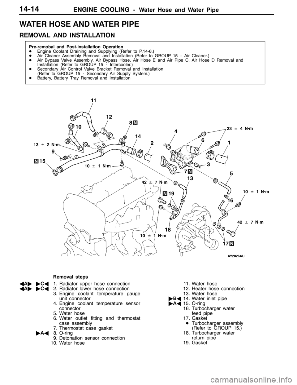
ENGINE COOLING -Water Hose and Water Pipe14-14
WATER HOSE AND WATER PIPE
REMOVAL AND INSTALLATION
Pre-remobal and Post-installation Operation
DEngine Coolant Draining and Supplying (Refer to P.14-6.)
DAir Cleaner Assembly Removal and Installation (Refer to GROUP 15 - Air Cleaner.)
DAir Bypass Valve Assembly, Air Bypass Hose, Air Hose E and Air Pipe C, Air Hose D Removal and
Installation (Refer to GROUP 15 - Intercooler.)
DSecondary Air Control Valve Bracket Removal and Installation
(Refer to GROUP 15 - Secondary Air Supply System.)
DBattery, Battery Tray Removal and Installation
3 4
5 6
7 8
9
1012
10±1 N·m
42±7 N·m 13±2 N·m
11
1
2
23±4 N·m
18
1716 1514
13
19
10±1 N·m
42±7 N·m
10±1 N·m
Removal steps
AA""CA1. Radiator upper hose connection
AA""CA2. Radiator lower hose connection
3. Engine coolant temperature gauge
unit connector
4. Engine coolant temperature sensor
connector
5. Water hose
6. Water outlet fitting and thermostat
case assembly
7. Thermostat case gasket
"AA8. O-ring
9. Detonation sensor connection
10. Water hose11. Water hose
12. Heater hose connection
13. Water hose
"BA14. Water inlet pipe
"AA15. O-ring
16. Turbocharger water
feed pipe
17. Gasket
DTurbocharger assembly
(Refer to GROUP 15.)
18. Turbocharger water
return pipe
19. Gasket
Page 758 of 1449

ENGINE ELECTRICAL -Ignition System16-26
IGNITION SYSTEM
GENERAL INFORMATION
This system is equipped with two ignition coils (A
and B) with built-in power transistors for the No.
1 and No. 4 cylinders and the No. 2 and No. 3
cylinders respectively.
Interruption of the primary current flowing in the
primary side of ignition coil A generates a high
voltage in the secondary side of ignition coil A.
The high voltage thus generated is applied to the
spark plugs of No. 1 and No. 4 cylinders to generate
sparks. At the time that the sparks are generated
at both spark plugs, if one cylinder is at the
compression stroke, the other cylinder is at the
exhaust stroke, so that ignition of the compressed
air/fuel mixture occurs only for the cylinder which
is at the compression stroke.
In the same way, when the primary current flowing
in ignition coil B is interrupted, the high voltage
thus generated is applied to the spark plugs of
No. 2 and No. 3 cylinders.
The Engine-ECU turns the two power transistors
inside the ignition coils alternately on and off. Thiscauses the primary currents in the ignition coils
to be alternately interrupted and allowed to flow
to fire the cylinders in the order 1-3-4-2.
The Engine-ECU determines which ignition coil
should be controlled by means of the signals from
the camshaft position sensor which is incorporated
in the camshaft and from the crank angle sensor
which is incorporated in the crankshaft. It also
detects the crankshaft position in order to provide
ignition at the most appropriate timing in response
to the engine operation conditions. It also detects
the crankshaft position in order to provide ignition
at the most appropriate timing in response to the
engine operation conditions.
When the engine is cold or operated at high
altitudes, the ignition timing is slightly advanced
to provide optimum performance.
When the automatic transmission shifts gears, the
ignition timing is also retarded in order to reduce
output torque, thereby alleviating shifting shocks.
SYSTEM DIAGRAM
Barometric pressure sensor
Intake air temperature sensor
Engine coolant temperature sensor
Camshaft position sensor
Crank angle sensor
Ignition switch - ST
Vehicle speed signalEngine-ECU
Ignition coil A
Ignition coil B Ignition switch
Spark plugBattery
To tachometerCylinder No. Air flow sensor
1 4
23
Detonation sensor
Page 780 of 1449

ENGINE AND EMISSION CONTROL -Emission Control System
Vacuum tank
Alternator
Purge control solenoid valve
17-10
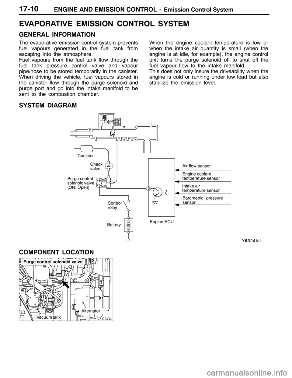
EVAPORATIVE EMISSION CONTROL SYSTEM
GENERAL INFORMATION
The evaporative emission control system prevents
fuel vapours generated in the fuel tank from
escaping into the atmosphere.
Fuel vapours from the fuel tank flow through the
fuel tank pressure control valve and vapour
pipe/hose to be stored temporarily in the canister.
When driving the vehicle, fuel vapours stored in
the canister flow through the purge solenoid and
purge port and go into the intake manifold to be
sent to the combustion chamber.When the engine coolant temperature is low or
when the intake air quantity is small (when the
engine is at idle, for example), the engine control
unit turns the purge solenoid off to shut off the
fuel vapour flow to the intake manifold.
This does not only insure the driveability when the
engine is cold or running under low load but also
stabilize the emission level.
SYSTEM DIAGRAM
BatteryIntake air
temperature sensor
Barometric pressure
sensor
Check
valve
Canister
Control
relay
Purge control
solenoid valve
(ON: Open)
Engine-ECUEngine coolant
temperature sensor Air flow sensor
COMPONENT LOCATION
Page 781 of 1449

ENGINE AND EMISSION CONTROL -Emission Control System17-11
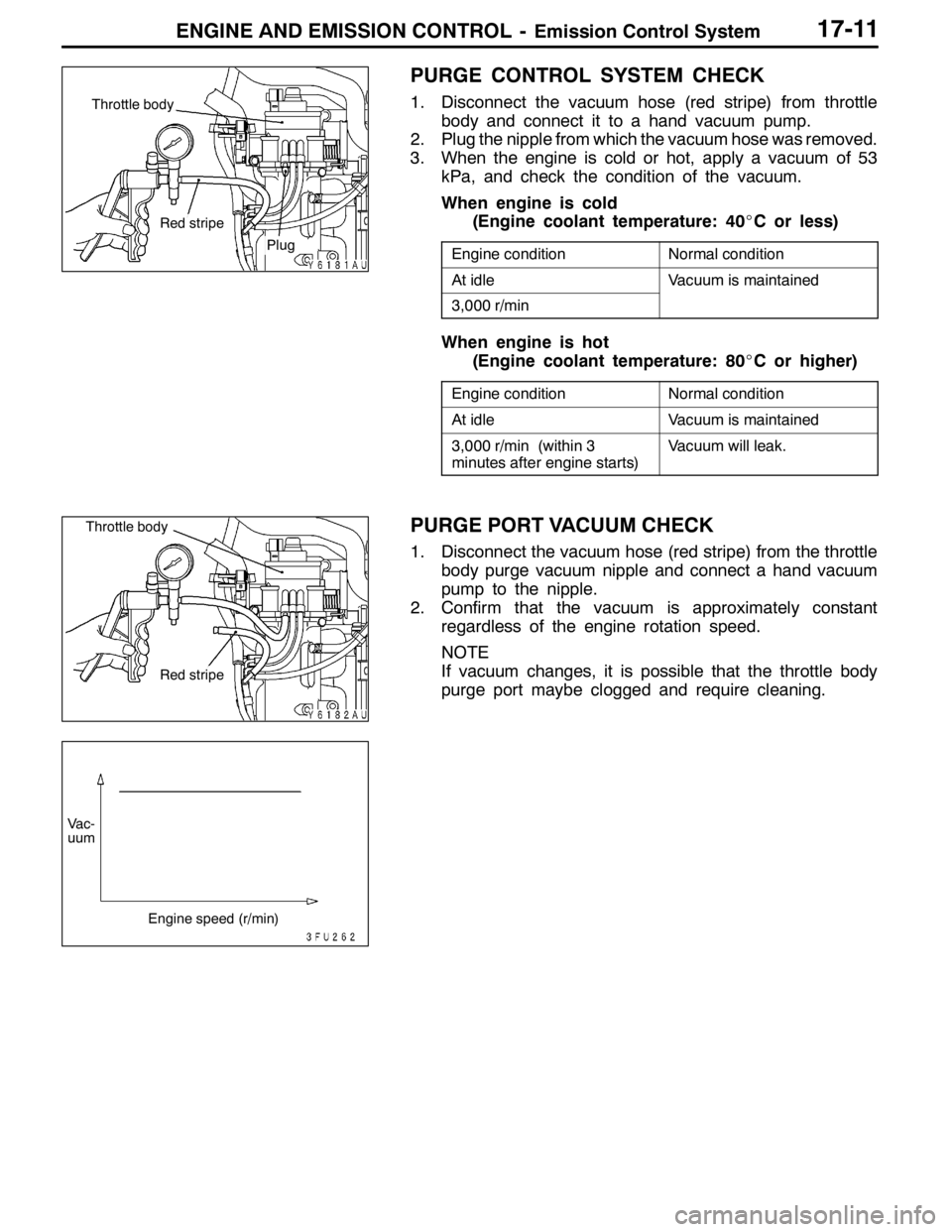
PURGE CONTROL SYSTEM CHECK
1. Disconnect the vacuum hose (red stripe) from throttle
body and connect it to a hand vacuum pump.
2. Plug the nipple from which the vacuum hose was removed.
3. When the engine is cold or hot, apply a vacuum of 53
kPa, and check the condition of the vacuum.
When engine is cold
(Engine coolant temperature: 40_C or less)
Engine conditionNormal condition
At idleVacuum is maintained
3,000 r/min
When engine is hot
(Engine coolant temperature: 80_C or higher)
Engine conditionNormal condition
At idleVacuum is maintained
3,000 r/min (within 3
minutes after engine starts)Vacuum will leak.
PURGE PORT VACUUM CHECK
1. Disconnect the vacuum hose (red stripe) from the throttle
body purge vacuum nipple and connect a hand vacuum
pump to the nipple.
2. Confirm that the vacuum is approximately constant
regardless of the engine rotation speed.
NOTE
If vacuum changes, it is possible that the throttle body
purge port maybe clogged and require cleaning.
Red stripe
Plug
Throttle body
Red stripe
Throttle body
Vac-
uum
Engine speed (r/min)
Page 783 of 1449

ENGINE AND EMISSION CONTROL -Emission Control System17-13
EXHAUST GAS RECIRCULATION (EGR) SYSTEM
GENERAL INFORMATION
The exhaust gas recirculation (EGR) system lowers
the nitrogen oxide (NOx) emission level. When the
air/fuel mixture combustion temperature is high,
a large quantity of nitrogen oxides (NOx) is
generated in the combustion chamber. Therefore,
this system recirculates part of emission gas fromthe exhaust port of the cylinder head to the
combustion chamber through the intake manifold
to decrease the air/fuel mixture combustion
temperature, resulting in reduction of NOx.
The EGR flow rate is controlled by the EGR valve
so as not to decrease the driveability.
OPERATION
The EGR valve is being closed and does not
recirculate exhaust gases under one of the following
conditions. Otherwise, the EGR valve is opened
and recirculates exhaust gases.DThe engine coolant temperature is low.
DThe engine is at idle.
DThe throttle valve is widely opened.
SYSTEM DIAGRAM
ON Throttle body
EGR control
solenoid valve
Engine
control
relay
Battery EGR valve
Crank angle sensor
Throttle position sensor Engine-ECU
Engine coolant
temperature sensor Air flow sensor
Page 784 of 1449

ENGINE AND EMISSION CONTROL -Emission Control System
EGR control solenoid valve
Vacuum tank
Alternator
EGR valve
Throttle body
17-14
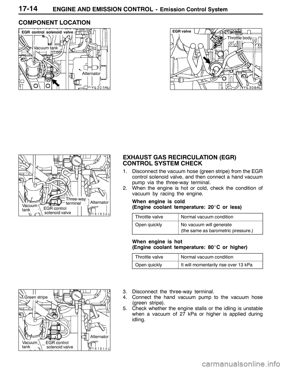
COMPONENT LOCATION
EXHAUST GAS RECIRCULATION (EGR)
CONTROL SYSTEM CHECK
1. Disconnect the vacuum hose (green stripe) from the EGR
control solenoid valve, and then connect a hand vacuum
pump via the three-way terminal.
2. When the engine is hot or cold, check the condition of
vacuum by racing the engine.
When engine is cold
(Engine coolant temperature: 20_C or less)
Throttle valveNormal vacuum condition
Open quicklyNo vacuum will generate
(the same as barometric pressure.)
When engine is hot
(Engine coolant temperature: 80_C or higher)
Throttle valveNormal vacuum condition
Open quicklyIt will momentarily rise over 13 kPa
3. Disconnect the three-way terminal.
4. Connect the hand vacuum pump to the vacuum hose
(green stripe).
5. Check whether the engine stalls or the idling is unstable
when a vacuum of 27 kPa or higher is applied during
idling.
Three-way
terminal
EGR control
solenoid valveVacuum
tankAlternator
EGR control
solenoid valveVacuum
tank
Alternator
Green stripe
Page 1322 of 1449

54A-2
CHASSIS
ELECTRICAL
CONTENTS
BATTERY 4..............................
SERVICE SPECIFICATION 4....................
ON-VEHICLE SERVICE 4......................
Fluid Level and Specific Gravity Check 4........
Charging 4.................................
Battery Testing Procedure 5...................
IGNITION SWITCH AND IMMOBILIZER
SYSTEM 6...............................
SPECIAL TOOLS 6............................
TROUBLESHOOTING 6........................
IMMOBILIZER-ECU CHECK 10.................
IGNITION SWITCH 11..........................
COMBINATION METER 14................
SERVICE SPECIFICATIONS 14.................
SEALANT 14..................................
SPECIAL TOOLS 15...........................
TROUBLESHOOTING 15.......................
ON-VEHICLE SERVICE 19.....................Speedometer Check 19......................
Tachometer Check 20........................
Fuel Gauge Unit Check 20....................
Engine Coolant Temperature Gauge
Unit Check 21...............................
COMBINATION METER 22.....................
HEADLAMP ASSEMBLY 24...............
SERVICE SPECIFICATIONS 24.................
TROUBLESHOOTING 24.......................
ON-VEHICLE SERVICE 24.....................
Headlamp Aiming 24.........................
Headlamp Intensity Measurement 28...........
Headlamp Bulb(low beam)Replacement28 ....
Headlamp Bulb(high beam)Replacement29 ...
Position Lamp Bulb Replacement29 ...........
Front Turn Signal Lamp Bulb Replacement29 ...
Headlamp Auto Cut Adjustment Procedure29 ...
HeadlampAuto Cut Function Check 29.........
HEADLAMP ASSEMBLY 30....................
CONTINUED ON NEXT PAGE