2007 MITSUBISHI LANCER EVOLUTION coolant temperature
[x] Cancel search: coolant temperaturePage 663 of 1449

MPI -On-vehicle Service13A-131
COMPONENT LOCATION
NameSymbolNameSymbol
A/C relayJFuel pump relay 1, 2Q
A/C switchTFuel pump relay 3H
Air flow sensor (integrated intake air tempera-
ture sensor and barometric pressure sensor)OFuel pump resistorH
Camshaft position sensorNIdle speed control servo (stepper motor)G
Crank angle sensorKIgnition coil (integrated power transister)M
Detonation sensorEInjectorC
Diagnosis connectorSOxygen sensor (front)L
EGR control solenoid valveDOxygen sensor (rear)X
Engine control relayIPower steering fluid pressure switchA
Engine coolant temperature sensorNResistor (for injector)H
Engine warning lamp (check engine lamp)RSecondary air control solenoid valveD
Engine-ECUUThrottle position sensorG
Fan motor relayJVehicle speed sensorF
Fuel pressure control solenoid valveBWaste gate solenoid valveP
ABCDEFGHIJK
LMNOP
QRSTU
Page 665 of 1449
MPI -On-vehicle Service13A-133
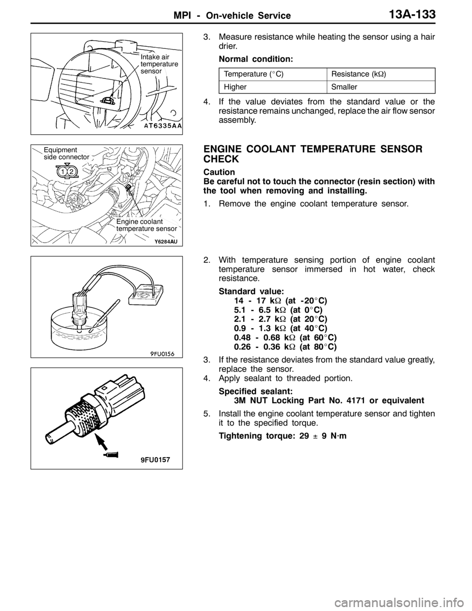
3. Measure resistance while heating the sensor using a hair
drier.
Normal condition:
Temperature (_C)Resistance (kΩ)
HigherSmaller
4. If the value deviates from the standard value or the
resistance remains unchanged, replace the air flow sensor
assembly.
ENGINE COOLANT TEMPERATURE SENSOR
CHECK
Caution
Be careful not to touch the connector (resin section) with
the tool when removing and installing.
1. Remove the engine coolant temperature sensor.
2. With temperature sensing portion of engine coolant
temperature sensor immersed in hot water, check
resistance.
Standard value:
14 - 17 kΩ(at - 20_C)
5.1 - 6.5 kΩ(at 0_C)
2.1 - 2.7 kΩ(at 20_C)
0.9 - 1.3 kΩ(at 40_C)
0.48 - 0.68 kΩ(at 60_C)
0.26 - 0.36 kΩ(at 80_C)
3. If the resistance deviates from the standard value greatly,
replace the sensor.
4. Apply sealant to threaded portion.
Specified sealant:
3M NUT Locking Part No. 4171 or equivalent
5. Install the engine coolant temperature sensor and tighten
it to the specified torque.
Tightening torque: 29±9 N·m
Intake air
temperature
sensor
Engine coolant
temperature sensor
Equipment
side connector
12
Page 670 of 1449
MPI -On-vehicle Service13A-138
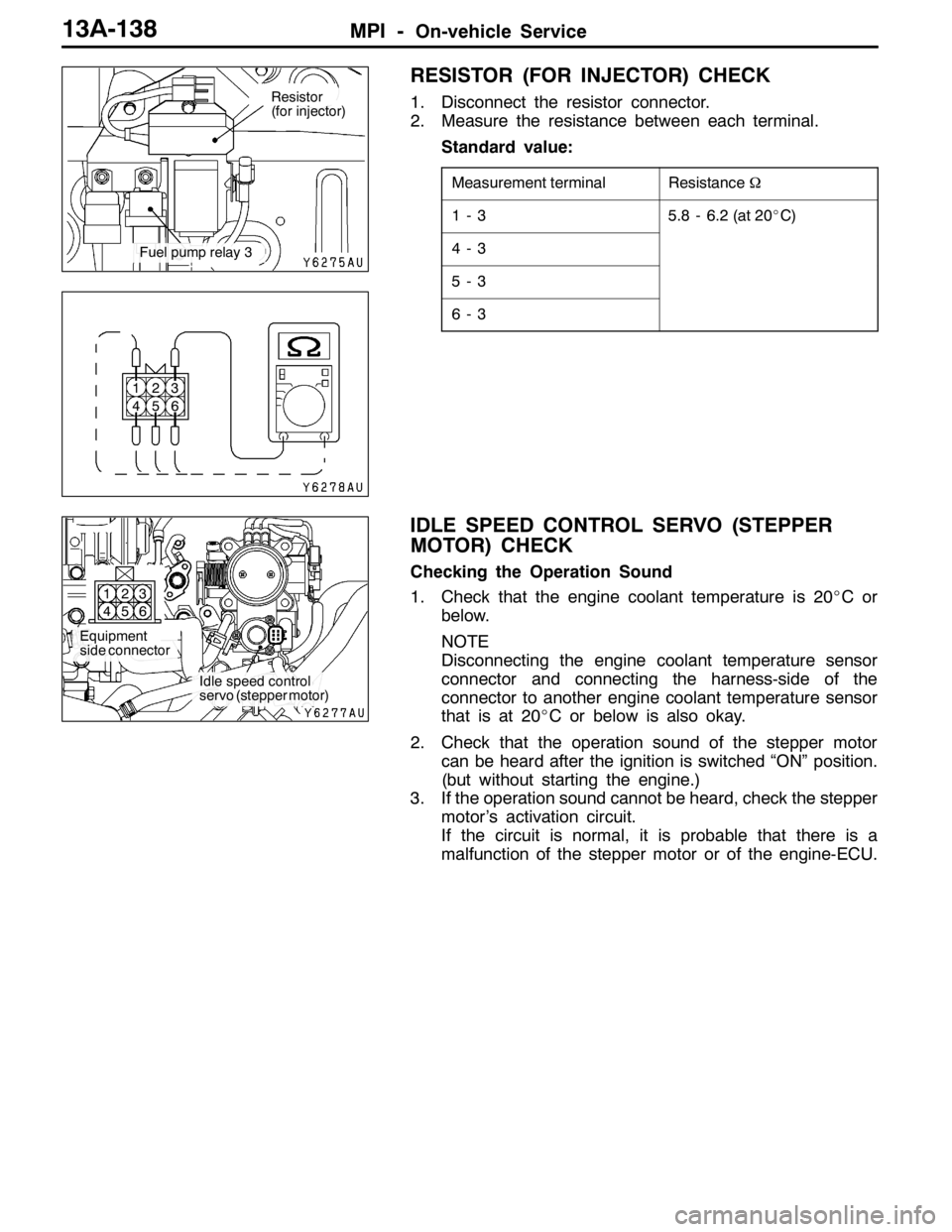
RESISTOR (FOR INJECTOR) CHECK
1. Disconnect the resistor connector.
2. Measure the resistance between each terminal.
Standard value:
Measurement terminalResistanceΩ
1-35.8 - 6.2 (at 20_C)
4-3
5-3
6-3
IDLE SPEED CONTROL SERVO (STEPPER
MOTOR) CHECK
Checking the Operation Sound
1. Check that the engine coolant temperature is 20_Cor
below.
NOTE
Disconnecting the engine coolant temperature sensor
connector and connecting the harness-side of the
connector to another engine coolant temperature sensor
that is at 20_C or below is also okay.
2. Check that the operation sound of the stepper motor
can be heard after the ignition is switched “ON” position.
(but without starting the engine.)
3. If the operation sound cannot be heard, check the stepper
motor’s activation circuit.
If the circuit is normal, it is probable that there is a
malfunction of the stepper motor or of the engine-ECU.
Resistor
(for injector)
Fuel pump relay 3
1
42
53
6
Equipment
side connector
Idle speed control
servo (stepper motor) 1
42
53
6
Page 690 of 1449

ENGINE COOLING -GeneralInformation/
Service Specifications/Lubricant/Sealant14-2
GENERAL INFORMATION
The cooling system is designed to keep every part
of the engine at appropriate temperature in
whatever condition the engine may be operated.
The cooling method is of the water-cooled, pressure
forced circulation type in which the water pump
pressurizes coolant and circulates it throughout the
engine. If the coolant temperature exceeds the
prescribed temperature, the thermostat opens to
circulate the coolant through the radiator as well
so that the heat absorbed by the coolant may be
radiated into the air.The water pump is of the centrifugal type and is
driven by the drive belt from the crankshaft.
The radiator is the corrugated fin, down flow type.
The cooling fan is controlled by the radiator fan
controller and engine-ECU depend on driving
conditions.
ItemSpecification
Radiator performance kJ/h216,700
SERVICE SPECIFICATIONS
ItemsStandard valueLimit
Radiator cap opening pressure kPa93 - 12383
Range of coolant antifreeze concentration of radiator %30 - 60-
ThermostatValve opening temperature of thermostat_C80±1.5-
Full-opening temperature of thermostat_C93-
Valve lift (at 93_C) mm9.5 or more-
LUBRICANT
ItemSpecified coolantQuantity L
Engine coolantMITSUBISHI GENUINE COOLANT or equivalent6.0Enginecoolant
(including reserve tank)
MITSUBISHIGENUINECOOLANTorequivalent6.0
SEALANT
ItemSpecified sealantRemark
Cylinder block drain plug3M Nut Locking Part No. 4171 or equivalentDrying sealant
Page 692 of 1449
ENGINE COOLING -Troubleshooting14-4
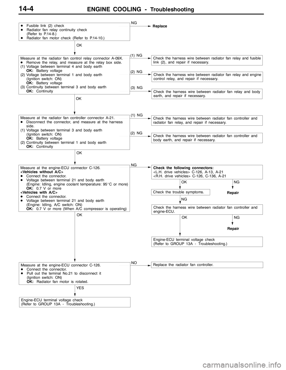
Measure at the engine-ECU connector C-126.
DConnect the connector.
DPull out the teminal No.21 to disconnect it
(Ignition switch: ON)
OK:Radiator fan motor is rotated.
YES
Engine-ECU terminal voltage check
(Refer to GROUP 13A - Troubleshooting.)NO
Replace the radiator fan controller.
NG
Repair
OK
NG
Repair
OK
Check the harness wire between radiator fan controller and
engine-ECU.
Measure at the engine-ECU connector C-126.
DConnect the connector.
DVoltage between terminal 21 and body earth
(Engine: Idling, engine coolant temperature: 95_C or more)
OK:0.7 V or more
DConnect the connector.
DVoltage between terminal 21 and body earth
(Engine: Idling, A/C switch: ON)
OK:0.7 V or more (When A/C compressor is operating)NG
(2) NGCheck the harness wire between radiator fan controller and
body earth, and repair if necessary.
OK
Measure at the radiator fan controller connector A-21.
DDisconnect the connector, and measure at the harness
side.
(1) Voltage between terminal 3 and body earth
(Ignition switch: ON)
OK:Battery voltage
(2) Continuity between terminal 1 and body earth
OK:Continuity(1) NGCheck the harness wire between radiator fan controller and
radiator fan relay, and repair if necessary.
(3) NGCheck the harness wire between radiator fan relay and body
earth, and repair if necessary.
(2) NGCheck the harness wire between radiator fan relay and engine
control relay, and repair if necessary.
OK
Measure at the radiator fan control relay connector A-09X.
DRemove the relay, and measure at the relay box side.
(1) Voltage between terminal 4 and body earth
OK:Battery voltage
(2) Voltage between terminal 1 and body earth
(Ignition switch: ON)
OK:Battery voltage
(3) Continuity between terminal 3 and body earth
OK:Continuity(1) NGCheck the harness wire between radiator fan relay and fusible
link (2), and repair if necessary.
DFusible link (2) check
DRadiator fan relay continuity check
(Refer to P.14-8.)
DRadiator fan motor check (Refer to P.14-10.)NG
Replace
OK
OK
Engine-ECU terminal voltage check
(Refer to GROUP 13A - Troubleshooting.)
Check the following connectors:
NG
Check the trouble symptoms.
Page 693 of 1449
ENGINE COOLING -Troubleshooting14-5
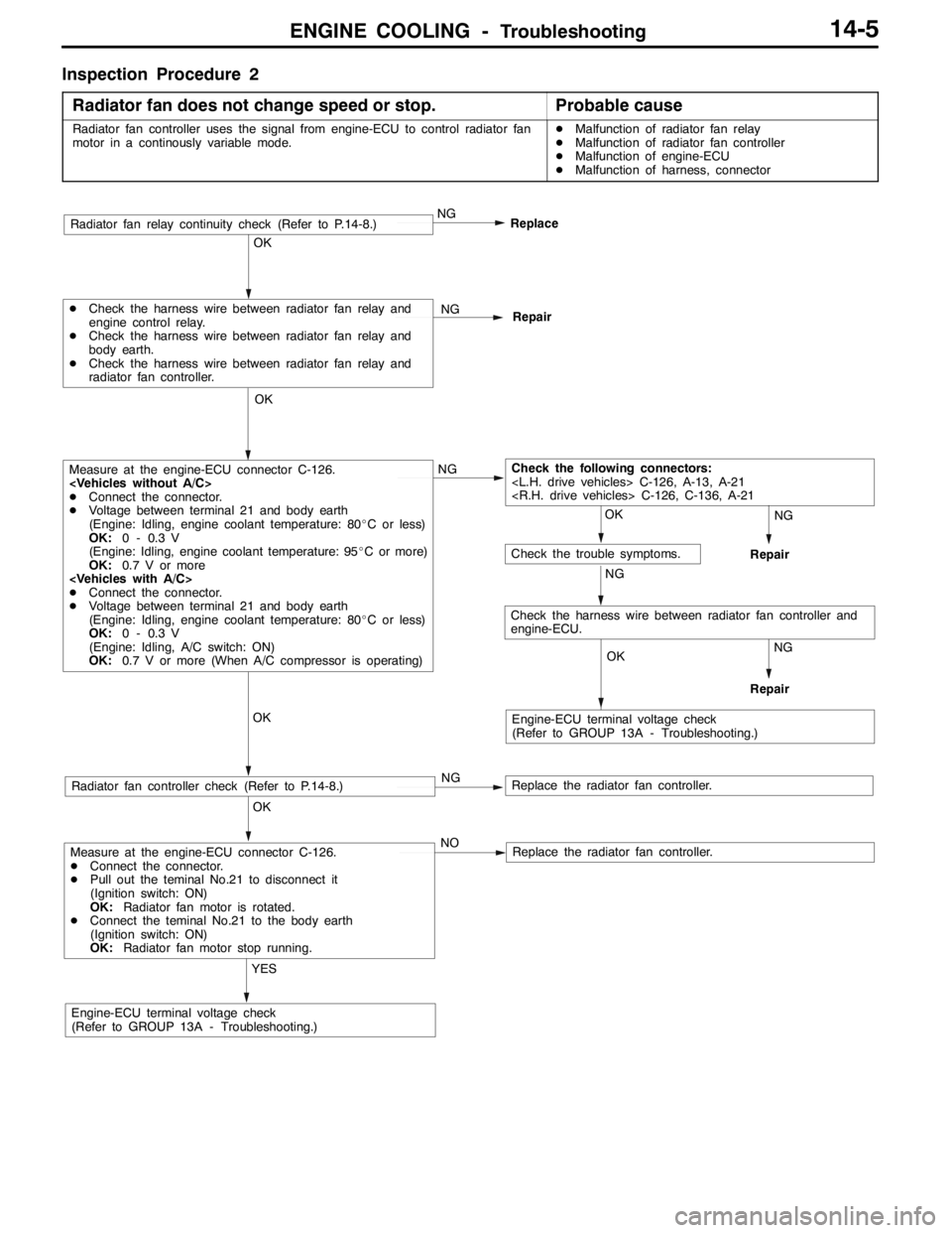
Inspection Procedure 2
Radiator fan does not change speed or stop.
Probable cause
Radiator fan controller uses the signal from engine-ECU to control radiator fan
motor in a continously variable mode.DMalfunction of radiator fan relay
DMalfunction of radiator fan controller
DMalfunction of engine-ECU
DMalfunction of harness, connector
Measure at the engine-ECU connector C-126.
DConnect the connector.
DPull out the teminal No.21 to disconnect it
(Ignition switch: ON)
OK:Radiator fan motor is rotated.
DConnect the teminal No.21 to the body earth
(Ignition switch: ON)
OK:Radiator fan motor stop running.
YES
Engine-ECU terminal voltage check
(Refer to GROUP 13A - Troubleshooting.)NO
Replace the radiator fan controller.
OK
Radiator fan controller check (Refer to P.14-8.)NGReplace the radiator fan controller.
OK
Measure at the engine-ECU connector C-126.
DConnect the connector.
DVoltage between terminal 21 and body earth
(Engine: Idling, engine coolant temperature: 80_C or less)
OK:0 - 0.3 V
(Engine: Idling, engine coolant temperature: 95_C or more)
OK:0.7 V or more
DConnect the connector.
DVoltage between terminal 21 and body earth
(Engine: Idling, engine coolant temperature: 80_C or less)
OK:0 - 0.3 V
(Engine: Idling, A/C switch: ON)
OK:0.7 V or more (When A/C compressor is operating)NG
OK
DCheck the harness wire between radiator fan relay and
engine control relay.
DCheck the harness wire between radiator fan relay and
body earth.
DCheck the harness wire between radiator fan relay and
radiator fan controller.NG
Repair
NG
Replace
OK
OK
OK
Check the following connectors:
NG
Engine-ECU terminal voltage check
(Refer to GROUP 13A - Troubleshooting.)
Check the trouble symptoms.
NG
NG
Repair
Repair
Radiator fan relay continuity check (Refer to P.14-8.)
Check the harness wire between radiator fan controller and
engine-ECU.
Page 695 of 1449

ENGINE COOLING -On-vehicle ServiceENGINE COOLING -On-vehicle Service14-7
3. Remove the cylinder block drain plug from the cylinder
block to drain the engine coolant.
4. Remove the reserve tank to drain the engine coolant.
5. When the engine coolant has drained, pour in water from
the radiator cap to clean the engine coolant line.
6. Coat the thread of the cylinder block drain plug with the
specified sealant and tighten to the specified torque.
Specified sealant:
3M Nut Locking Part No. 4171 or equivalent
7. Securely tighten the radiator drain plug.
8. Install the under cover.
(Refer to GROUP 51 - Front Bumper.)
9. Install the reserve tank.
10. Slowly pour the engine coolant into the mouth of the
radiator until the radiator is full, and pour also into the
reserve tank up to the FULL line.
Recommended anti-freeze:
MITUBISHI GENUINE COOLANT or equivalent
Quantity: 6.0 L
Caution
Do not use alcohol or methanol anti-freeze or any
engine coolants mixed with alcohol or methanol
anti-freeze. The use of an improper anti-freeze can
cause the corrosion of the aluminium components.
11. Install the radiator cap securely.
12. Start the engine and warm the engine until the thermostat
opens. (Touch the radiator hose with your hand to check
that warm water is flowing.)
13. After the thermostat opens, race the engine several times,
and then stop the engine.
14. Cool down the engine, and then pour engine coolant into
the reserve tank until the level reaches the FULL line. If
the level is low, repeat the operation from step 11.
CONCENTRATION MEASUREMENT
Measure the temperature and specific gravity of the engine
coolant to check the antifreeze concentration.
Standard value: 30 - 60 % (allowable concentration range)
RECOMMENDED ANTI-FREEZE
AntifreezeAllowable concentration
MITSUBISHI GENUINE COOLANT
or equivalent30 - 60 %
Caution
If the concentration of the anti-freeze is below 30 %, the
anti-corrosion property will be adversely affected. In
addition, if the concentration is above 60 %, both the
anti-freezing and engine cooling properties will decrease,
affecting the engine adversely. For these reasons, be
sure to maintain the concentration level within the
specified range.
44±5N·m
Water inlet
pipe
Page 696 of 1449
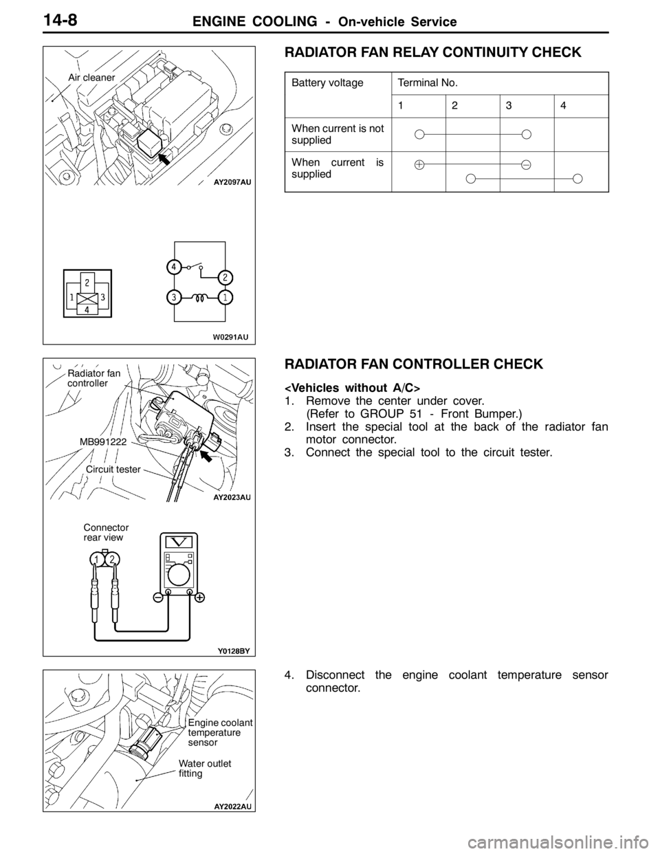
ENGINE COOLING -On-vehicle Service14-8
RADIATOR FAN RELAY CONTINUITY CHECK
Battery voltageTerminal No.
1234
When current is not
supplied
When current is
supplied
RADIATOR FAN CONTROLLER CHECK
1. Remove the center under cover.
(Refer to GROUP 51 - Front Bumper.)
2. Insert the special tool at the back of the radiator fan
motor connector.
3. Connect the special tool to the circuit tester.
4. Disconnect the engine coolant temperature sensor
connector.
Air cleaner
Radiator fan
controller
MB991222
Circuit tester
Connector
rear view
Water outlet
fitting
Engine coolant
temperature
sensor