Page 1084 of 1449

ABS <4WD> -Troubleshooting35B-14
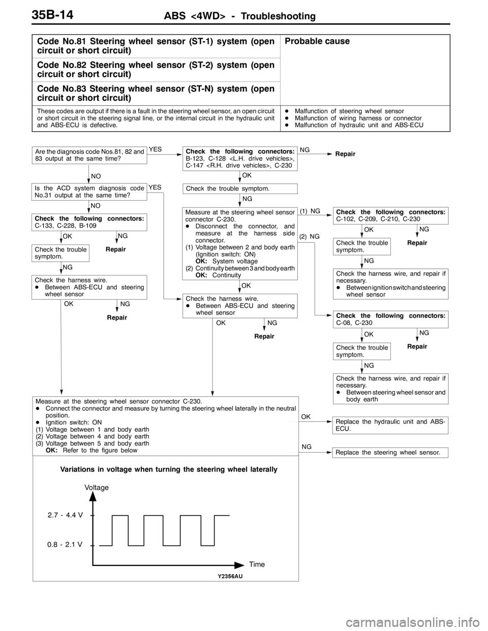
Code No.81 Steering wheel sensor (ST-1) system (open
circuit or short circuit)Probable cause
Code No.82 Steering wheel sensor (ST-2) system (open
circuit or short circuit)
Code No.83 Steering wheel sensor (ST-N) system (open
circuit or short circuit)
These codes are output if there is a fault in the steering wheel sensor, an open circuit
or short circuit in the steering signal line, or the internal circuit in the hydraulic unit
and ABS-ECU is defective.DMalfunction of steering wheel sensor
DMalfunction of wiring harness or connector
DMalfunction of hydraulic unit and ABS-ECU
NG
Repair
Replace the hydraulic unit and ABS-
ECU. OK NG YES
Repair
NOAre the diagnosis code Nos.81, 82 and
83 output at the same time?
OKCheck the following connectors:
B-123, C-128 ,
C-147 , C-230
YES
NO
Is the ACD system diagnosis code
No.31 output at the same time?
NG
Check the trouble symptom.
(1) NG
(2) NGNG
Repair
NG
OK
Check the trouble
symptom.
Check the following connectors:
C-102, C-209, C-210, C-230
Check the harness wire, and repair if
necessary.
DBetween ignition switch and steering
wheel sensor
NG
OK
Check the trouble
symptom.
Check the following connectors:
C-08, C-230
Check the harness wire, and repair if
necessary.
DBetween steering wheel sensor and
body earth
OK
Measure at the steering wheel sensor
connector C-230.
DDisconnect the connector, and
measure at the harness side
connector.
(1) Voltage between 2 and body earth
(Ignition switch: ON)
OK:System voltage
(2) Continuity between 3 and body earth
OK:Continuity
NG
RepairOK
Check the harness wire.
DBetween ABS-ECU and steering
wheel sensor NG
Repair
NG OK
Check the trouble
symptom.
Check the following connectors:
C-133, C-228, B-109
NG
Repair
Check the harness wire.
DBetween ABS-ECU and steering
wheel sensor
OK
Replace the steering wheel sensor. NG
Time Voltage
2.7 - 4.4 V
0.8 - 2.1 V
Variations in voltage when turning the steering wheel laterally
Measure at the steering wheel sensor connector C-230.
DConnect the connector and measure by turning the steering wheel laterally in the neutral
position.
DIgnition switch: ON
(1) Voltage between 1 and body earth
(2) Voltage between 4 and body earth
(3) Voltage between 5 and body earth
OK:Refer to the figure below
Page 1089 of 1449

ABS <4WD> -Troubleshooting35B-19
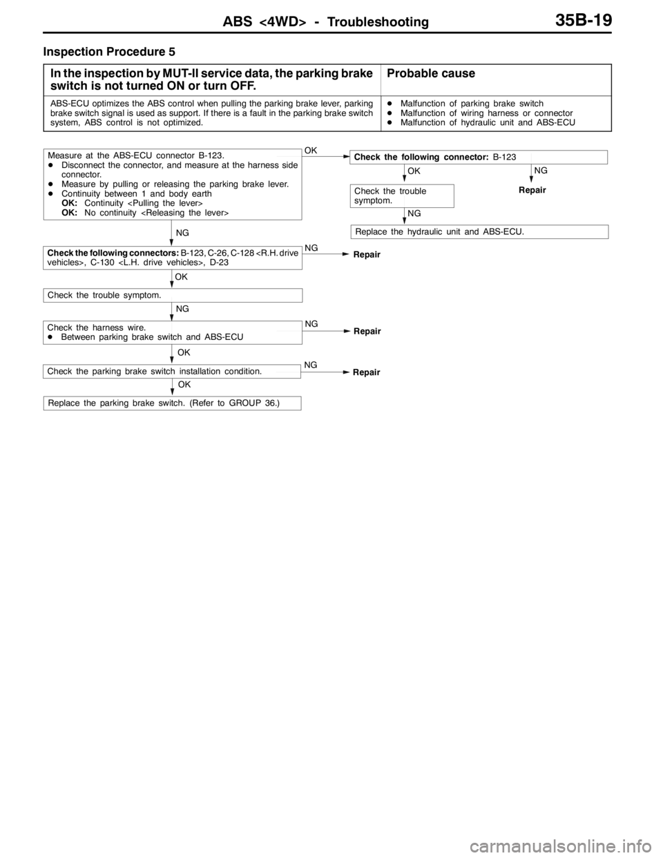
Inspection Procedure 5
In the inspection by MUT-II service data, the parking brake
switch is not turned ON or turn OFF.
Probable cause
ABS-ECU optimizes the ABS control when pulling the parking brake lever, parking
brake switch signal is used as support. If there is a fault in the parking brake switch
system, ABS control is not optimized.DMalfunction of parking brake switch
DMalfunction of wiring harness or connector
DMalfunction of hydraulic unit and ABS-ECU
OK
NG
NG
Check the harness wire.
DBetween parking brake switch and ABS-ECU
Replace the hydraulic unit and ABS-ECU.
OK
NG
OK
Check the trouble symptom.
Repair
NG
RepairCheck the following connectors:B-123, C-26, C-128
vehicles>, C-130 , D-23
Measure at the ABS-ECU connector B-123.
DDisconnect the connector, and measure at the harness side
connector.
DMeasure by pulling or releasing the parking brake lever.
DContinuity between 1 and body earth
OK:Continuity
OK:No continuity
NG
Repair
NG
OK
Check the trouble
symptom.
Check the following connector:B-123
OK
Replace the parking brake switch. (Refer to GROUP 36.)
NG
RepairCheck the parking brake switch installation condition.
Page 1096 of 1449
ABS <4WD> -Troubleshooting/On-vehicle Service35B-26
RESISTANCE AND CONTINUITY BETWEEN
HARNESS-SIDE CONNECTOR TERMINALS
1. Turn the ignition key to the “LOCK” (OFF) position.
2. Disconnect the ABS-ECU connector.
3. Check the resistance and continuity between the terminals
indicated in the table below.
4. The terminal layout is shown in the illustration.
ABS-ECU terminal No.SignalNormal condition
6-7Wheel speed sensor (rear left)1.24 - 1.64 kΩ
8-9Wheel speed sensor (rear right)
22 - 31Wheel speed sensor (front left)
29 - 30Wheel speed sensor (front right)
12 - Body earthEarthContinuity
34 - Body earthEarth
ON-VEHICLE SERVICE
WHEEL SPEED SENSOR OUTPUT VOLTAGE
CHECK
1. Lift up the vehicle and release the parking brake.
2. Move the lock lever of the ABS-ECU connector as shown
in the illustration, and then disconnect the ABS-ECU
connector.
3. Push up and unlock the hooks of the ABS-ECU connector
shown in the illustration, then remove the connector cover.
Lock lever
Page 1152 of 1449
BODY -Hood/Fender42-4
REMOVAL SERVICE POINTS
"AAHOOD HINGE BOLT INSTALLATION
Caution
Use the special parts as the aluminum hood uses special
coatings on the of the hood hinge bolt.
FENDER
SPECIAL TOOLS
ToolNumberNameUse
MB990784Ornament removerSide turn signal lamp removal
Page 1153 of 1449
BODY -Fender42-5
FENDER
REMOVAL AND INSTALLATION
Pre-removal and Post-installation OperationsDFront Bumper Removal and Installation (Refer to
GROUP 51.)DFront Deck Garnish Removal and Installation (Refer
to GROUP 51.)
13
2 4
5
Removal steps
DSide air dam (Refer to GROUP
51.)
1. Splash shield
AA""BA2. Side turn signal lamp (Refer to
GROUP 54A.)3. Deck garnish (Refer to GROUP
51-Windshield Wiper and Washer)
"AA4. Fender
5. Front fender bracket
Page 1154 of 1449
BODY -Fender42-6
REMOVAL SERVICE POINTS
AA"SIDE TURN SIGNAL LAMP REMOVAL
Use the special tool to release the claw part of the fender
panel and remove the side turn signal lamp.
INSTALLATION SERVICE POINT
"AAFENDER INSTALLATION
Caution
Use the special parts as the aluminum fender uses special
coatings on the fender mounting bolt and the washer.
"BASIDE TURN SIGNAL LAMP INSTALLATION
Engage the hook into the fender panel, and then install the
side turn signal lamp.
Claw part
A
Section A - A
A
Front of vehicle
Side turn signal lamp
Fender panel
MB990784
MB990784
Claw Hook
Fender
panel
Fender
panel
Front of vehicle
Page 1322 of 1449

54A-2
CHASSIS
ELECTRICAL
CONTENTS
BATTERY 4..............................
SERVICE SPECIFICATION 4....................
ON-VEHICLE SERVICE 4......................
Fluid Level and Specific Gravity Check 4........
Charging 4.................................
Battery Testing Procedure 5...................
IGNITION SWITCH AND IMMOBILIZER
SYSTEM 6...............................
SPECIAL TOOLS 6............................
TROUBLESHOOTING 6........................
IMMOBILIZER-ECU CHECK 10.................
IGNITION SWITCH 11..........................
COMBINATION METER 14................
SERVICE SPECIFICATIONS 14.................
SEALANT 14..................................
SPECIAL TOOLS 15...........................
TROUBLESHOOTING 15.......................
ON-VEHICLE SERVICE 19.....................Speedometer Check 19......................
Tachometer Check 20........................
Fuel Gauge Unit Check 20....................
Engine Coolant Temperature Gauge
Unit Check 21...............................
COMBINATION METER 22.....................
HEADLAMP ASSEMBLY 24...............
SERVICE SPECIFICATIONS 24.................
TROUBLESHOOTING 24.......................
ON-VEHICLE SERVICE 24.....................
Headlamp Aiming 24.........................
Headlamp Intensity Measurement 28...........
Headlamp Bulb(low beam)Replacement28 ....
Headlamp Bulb(high beam)Replacement29 ...
Position Lamp Bulb Replacement29 ...........
Front Turn Signal Lamp Bulb Replacement29 ...
Headlamp Auto Cut Adjustment Procedure29 ...
HeadlampAuto Cut Function Check 29.........
HEADLAMP ASSEMBLY 30....................
CONTINUED ON NEXT PAGE
Page 1323 of 1449

54A-3
SIDE TURN-SIGNAL LAMP 31............
SPECIAL TOOL 31............................
SIDE TURN-SIGNAL LAMP 31..................
ROOM LAMP 31.........................
TROUBLESHOOTING 31.......................
REAR COMBINATION LAMP 32...........
SPECIAL TOOL 32............................
TROUBLESHOOTING 32.......................
REAR COMBINATION LAMP 32................
HIGH-MOUNTED STOP LAMP 34.........
ON-VEHICLE SERVICE 34......................
High-mounted Stop Lamp Bulb Replacement 34.
HIGH-MOUNTED STOP LAMP 34................
LICENCE PLATE LAMP 35...............
ON-VEHICLE SERVICE 35.....................
License Plate Lamp Replacement 35...........
LICENCE PLATE LAMP 35.....................
HAZARD WARNING LAMP SWITCH 36....
SPECIAL TOOL 36............................
HAZARD WARNING LAMP SWITCH 36.........
HORN 37................................
CIGARETTE LIGHTER 37.................
COLUMN SWITCH 38....................
SPECIAL TOOL 38............................
COLUMN SWITCH 38..........................
CLOCK 40...............................
SPECIAL TOOL 40............................
CLOCK 40....................................
POLE ANTENNA 41......................
ROOF ANTENNA 42......................
DEFOGGER 42...........................
TROUBLESHOOTING 42......................
ON-VEHICLE SERVICE 43.....................
Printed Heater Check 43......................
Defogger Relay Continuity Check 43...........
DEFOGGER SWITCH 43.......................