2007 MITSUBISHI LANCER EVOLUTION turn signal
[x] Cancel search: turn signalPage 584 of 1449

MPI -Troubleshooting13A-52
INSPECTION CHART FOR TROUBLE SYMPTOMS
Inspection
procedureCheck itemsReference page
1Communication between MUT-IIand entire system is not possible.13A-54
2Only communication between MUT-IIand engine-ECU is not possible.13A-55
3Engine warning lamp does not illuminate immediately after ignition switch is set to ON position.13A-56
4Engine warning lamp stays illuminated and does not turn OFF.13A-57
5Starting disabled (Starter does not rotate.)13A-58
6Starting disabled (Starter rotates but initial combustion does not occur.)13A-59
7Starting disabled (Initial combustion occurs but is incomplete.)13A-61
Improper starting (Starting time is long.)
8Unstable idling (Rough idling, hunting)13A-63
Inappropriate idling speed (High or low idling speed)
Engine stalls (Die out) during idling
9Engine stalls when starting travel. (Pass out)13A-66
10Engine stalls during deceleration13A-67
11Pulsation (Hesitation, sag)13A-68
Poor acceleration
Stumbling
Surging
12Shock during acceleration13A-70
13Shock during deceleration13A-71
14Knocking13A-72
15Deviation of ignition interval13A-73
16Run on (Dieseling)13A-74
17Abnormal odor, white smoke, black smoke, high CO or HC concentration when idling13A-75
18Battery dies13A-77
19Overheating13A-79
20Abnormal radiator fan motor rotation13A-80
21A/C ineffective13A-81
22Engine-ECU power supply, engine control relay, ignition switch-IG1 system13A-82
23Fuel pump system13A-85
24Radiator fan control relay system13A-87
25Condenser fan relay system13A-89
26A/C switch system13A-92
27A/C compressor relay system13A-93
28A/C load signal system13A-95
29Secondary air control solenoid valve system13A-96
30Intercooler water spray circuit system13A-97
31Intercooler water spray lamp system13A-99
32Ignition coil (integrated power transistor) system13A-100
Page 596 of 1449

MPI -Troubleshooting13A-64
OK
To the next page
OK
Measure at the C-39 engine-ECU connector.
DMeasure the engine-ECU terminal voltage.
DEngine: Idling
DA/C switch: ON (A/C compressor driven state)
DVoltage between terminal No .24 and earth
(A/C setting temperature: Minimum temperature)
(Air volume: Maximum)
OK:1 V or less
(A/C setting temperature: indoor temperature)
(Air volume: Minimum)
OK:System voltageNGCheck the Inspection Procedure 28: A/C load signal system.
(Refer to P.13A-95.)
NG
Replace the alternator.
OK
Check the trouble symptoms.OKIntermittent malfunction
(Refer to GROUP 00 - Points to Note
for Intermittent Malfunctions.) NG
OK
Check the harness between the
alternator and engine-ECU.
DCheck for disconnection,
short-circuit and damage of the
output cable.Repair
OK
Measure at the C-40 engine-ECU
connector.
DMeasure the engine-ECU terminal
voltage.
DEngine: Idling (after warm-up)
DRadiator fan: Stopped
DVoltage between terminal No. 33
and earth
OK:Voltage rises 0.2 to 3.5 V when
headlamp is turned OFF and
ON.
DVoltage between terminal No. 41
and earth
OK:Voltage drops whenheadlamp
is turned OFF and ON.NGCheck the following connectors:
C-40, B-21, B-03NG
Repair
OK
Check the harness between the
engine-ECU and earth joint.
DCheck for disconnection and
damage of the earth cable.
(2) NGCheck the following connector:
C-39NG
Repair
NG
Replace the engine-ECU.
OK
Check the trouble symptoms.OKIntermittent malfunction
(Refer to GROUP 00 - Points to Note
for Intermittent Malfunctions.) NG
OK
Check the harness between the
engine-ECU and battery.
DCheck for disconnection,
short-circuit and damage of the
power cable.Repair
OK
Measure at the C-115 and C-126
engine-ECU connectors.
DMeasure the engine-ECU terminal
voltage.
(1) Voltage between terminal No. 80
and earth
OK:System voltage
(2) Voltage between terminal No. 13
and earth
Voltage between terminal No. 26
and earth
(Ignition switch: ON)
OK:0.5 V or less(1) NGCheck the following connectors:
C-115, C-129, C-05, C-135NG
Repair
OK
MUT-IIData list
DNo. 59: Oxygen sensor (rear)
(Refer to P.13A-105.)NGCheck the Code No. P0136: Oxygen sensor (rear) system.
(Refer to P.13A-27.)
From the previous page
Page 614 of 1449
MPI -Troubleshooting13A-82
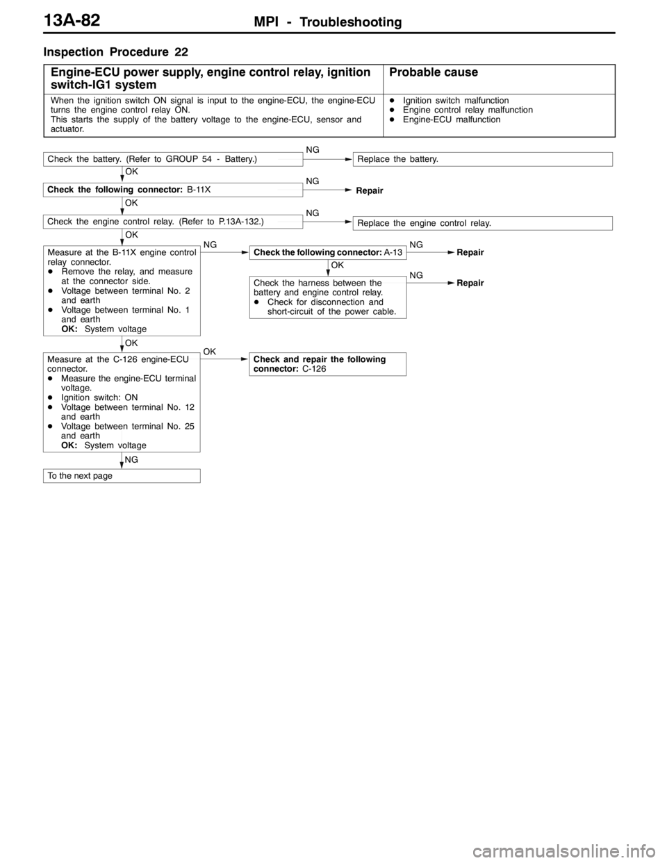
Inspection Procedure 22
Engine-ECU power supply, engine control relay, ignition
switch-IG1 system
Probable cause
When the ignition switch ON signal is input to the engine-ECU, the engine-ECU
turns the engine control relay ON.
This starts the supply of the battery voltage to the engine-ECU, sensor and
actuator.DIgnition switch malfunction
DEngine control relay malfunction
DEngine-ECU malfunction
OK
Check the engine control relay. (Refer to P.13A-132.)NGReplace the engine control relay.
OK
Check the following connector:B-11XNG
Check the battery. (Refer to GROUP 54 - Battery.)NGReplace the battery.
Repair
OK
OK
Measure at the B-11X engine control
relay connector.
DRemove the relay, and measure
at the connector side.
DVoltage between terminal No. 2
and earth
DVoltage between terminal No. 1
and earth
OK:System voltageNGCheck the following connector:A-13NG
OK
Check the harness between the
battery and engine control relay.
DCheck for disconnection and
short-circuit of the power cable.NGRepair
Repair
NGOK
Check and repair the following
connector:C-126Measure at the C-126 engine-ECU
connector.
DMeasure the engine-ECU terminal
voltage.
DIgnition switch: ON
DVoltage between terminal No. 12
and earth
DVoltage between terminal No. 25
and earth
OK:System voltage
To the next page
Page 619 of 1449
MPI -Troubleshooting13A-87
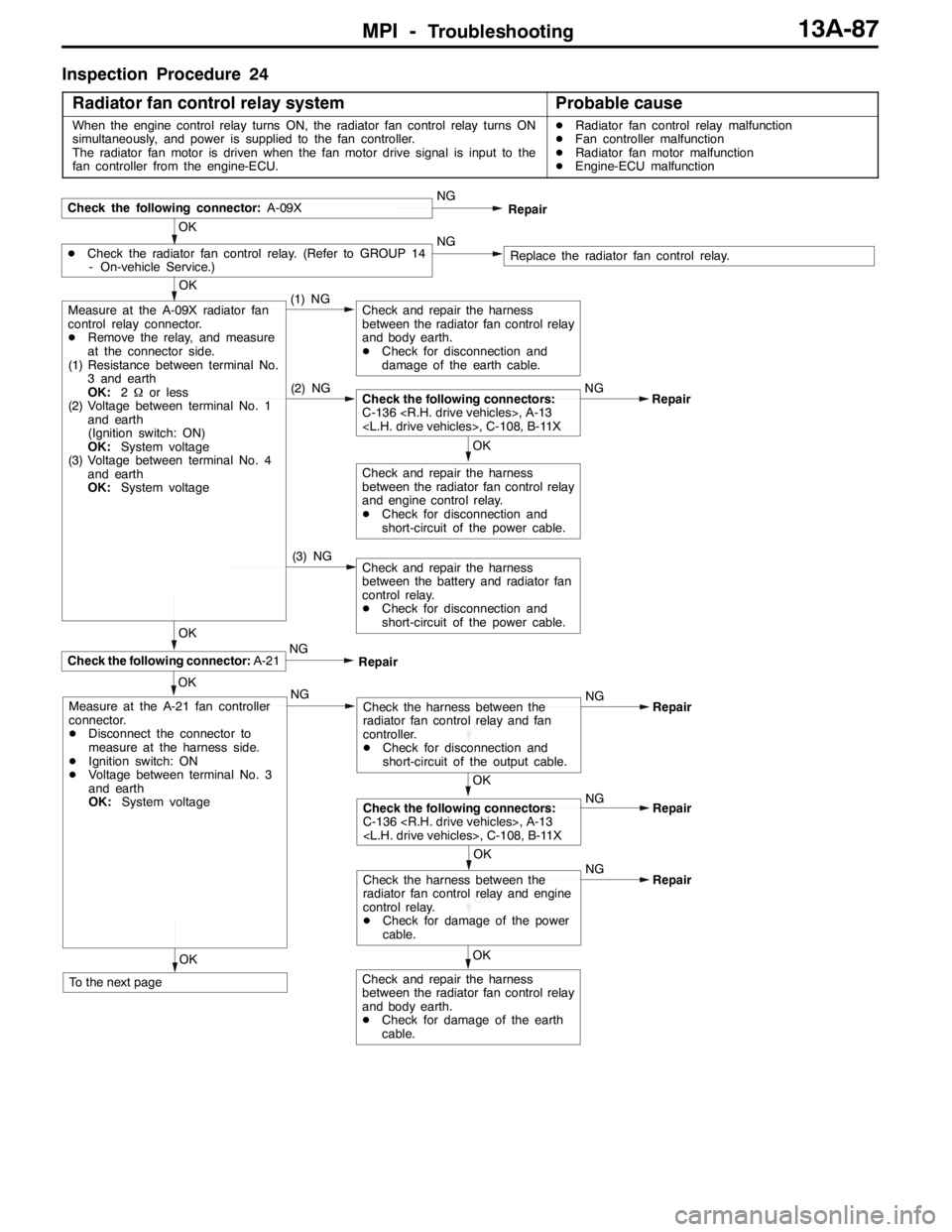
Inspection Procedure 24
Radiator fan control relay system
Probable cause
When the engine control relay turns ON, the radiator fan control relay turns ON
simultaneously, and power is supplied to the fan controller.
The radiator fan motor is driven when the fan motor drive signal is input to the
fan controller from the engine-ECU.DRadiator fan control relay malfunction
DFan controller malfunction
DRadiator fan motor malfunction
DEngine-ECU malfunction
OK
(1) NG
OK
DCheck the radiator fan control relay. (Refer to GROUP 14
- On-vehicle Service.)NGReplace the radiator fan control relay.
Check the following connector:A-09XNG
Repair
OK
OK
(2) NGCheck the following connectors:
C-136
OK
Check and repair the harness
between the radiator fan control relay
and body earth.
DCheck for disconnection and
damage of the earth cable.
Repair
OK
Check the following connector:A-21
Check and repair the harness
between the radiator fan control relay
and engine control relay.
DCheck for disconnection and
short-circuit of the power cable.
(3) NGCheck and repair the harness
between the battery and radiator fan
control relay.
DCheck for disconnection and
short-circuit of the power cable.
Measure at the A-09X radiator fan
control relay connector.
DRemove the relay, and measure
at the connector side.
(1) Resistance between terminal No.
3 and earth
OK:2Ωor less
(2) Voltage between terminal No. 1
and earth
(Ignition switch: ON)
OK:System voltage
(3) Voltage between terminal No. 4
and earth
OK:System voltage
NG
Repair
OK
Measure at the A-21 fan controller
connector.
DDisconnect the connector to
measure at the harness side.
DIgnition switch: ON
DVoltage between terminal No. 3
and earth
OK:System voltage
To the next pageNG
OK
Check the harness between the
radiator fan control relay and fan
controller.
DCheck for disconnection and
short-circuit of the output cable.NG
Repair
OK
Check the following connectors:
C-136
Repair
OK
OK
Check the harness between the
radiator fan control relay and engine
control relay.
DCheck for damage of the power
cable.NG
Repair
Check and repair the harness
between the radiator fan control relay
and body earth.
DCheck for damage of the earth
cable.
Page 621 of 1449
MPI -Troubleshooting13A-89
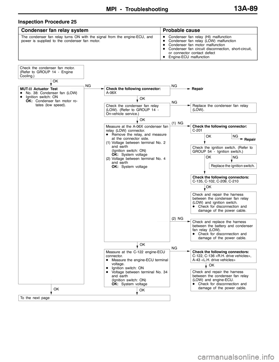
Inspection Procedure 25
Condenser fan relay system
Probable cause
The condenser fan relay turns ON with the signal from the engine-ECU, and
power is supplied to the condenser fan motor.DCondenser fan relay (HI) malfunction
DCondenser fan relay (LOW) malfunction
DCondenser fan motor malfunction
DCondenser fan circuit disconnection, short-circuit,
or connector contact defect
DEngine-ECU malfunction
OK
Check and repair the harness
between the condenser fan relay
(LOW) and engine-ECU.
DCheck for disconnection and
damage of the power cable.
(2) NG
OK
OK
Check the condenser fan motor.
(Refer to GROUP 14 - Engine
Cooling.)
OK
NG
OK
Check the following connector:
A-06X
OK
MUT-IIActuator Test
DNo. 38: Condenser fan (LOW)
DIgnition switch: ON
OK:Condenser fan motor ro-
tates (low speed).NG
OK
Measure at the C-122 engine-ECU
connector.
DMeasure the engine-ECU terminal
voltage.
DIgnition switch: ON
DVoltage between terminal No. 34
and earth
(Ignition switch: ON)
OK:System voltageRepair
NG
To the next page
NGReplace the condenser fan relay
(LOW).
OK
Check the condenser fan relay
(LOW). (Refer to GROUP 14 -
On-vehicle service.)
(1) NGMeasure at the A-06X condenser fan
relay (LOW) connector.
DRemove the relay, and measure
at the connector side.
(1) Voltage between terminal No. 2
and earth
(Ignition switch: ON)
OK:System voltage
(2) Voltage between terminal No. 4
and earth
OK:System voltage
NG
Repair OK
OK
Check the following connectors:
C-135, C-102, C-209, C-210
Check and repair the harness
between the condenser fan relay
(LOW) and ignition switch.
DCheck for disconnection and
damage of the power cable.
Check the following connectors:
C-122, C-136
A-43
Check the following connector:
C-201
NG
Check the ignition switch. (Refer to
GROUP 54 - Ignition switch.)
Replace the ignition switch.
Check and replace the harness
between the battery and condenser
fan relay (LOW).
DCheck for disconnection and
damage of the power cable.
Page 624 of 1449
MPI -Troubleshooting13A-92
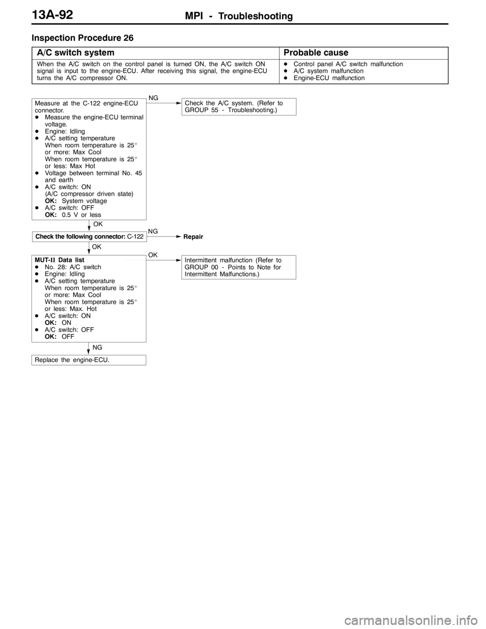
Inspection Procedure 26
A/C switch system
Probable cause
When the A/C switch on the control panel is turned ON, the A/C switch ON
signal is input to the engine-ECU. After receiving this signal, the engine-ECU
turns the A/C compressor ON.DControl panel A/C switch malfunction
DA/C system malfunction
DEngine-ECU malfunction
NG
Replace the engine-ECU.
Check the A/C system. (Refer to
GROUP 55 - Troubleshooting.)NG
OK
Intermittent malfunction (Refer to
GROUP 00 - Points to Note for
Intermittent Malfunctions.)MUT-IIData list
DNo. 28: A/C switch
DEngine: Idling
DA/C setting temperature
When room temperature is 25_
or more: Max Cool
When room temperature is 25_
or less: Max. Hot
DA/C switch: ON
OK:ON
DA/C switch: OFF
OK:OFFOK NG
OK
Check the following connector:C-122
Repair
Measure at the C-122 engine-ECU
connector.
DMeasure the engine-ECU terminal
voltage.
DEngine: Idling
DA/C setting temperature
When room temperature is 25_
or more: Max Cool
When room temperature is 25_
or less: Max Hot
DVoltage between terminal No. 45
and earth
DA/C switch: ON
(A/C compressor driven state)
OK:System voltage
DA/C switch: OFF
OK:0.5 V or less
Page 625 of 1449
MPI -Troubleshooting13A-93
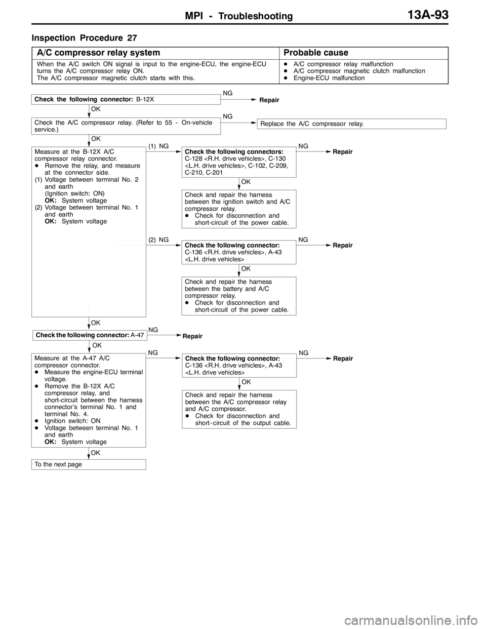
Inspection Procedure 27
A/C compressor relay system
Probable cause
When the A/C switch ON signal is input to the engine-ECU, the engine-ECU
turns the A/C compressor relay ON.
The A/C compressor magnetic clutch starts with this.DA/C compressor relay malfunction
DA/C compressor magnetic clutch malfunction
DEngine-ECU malfunction
OK
(2) NGCheck the following connector:
C-136
Check and repair the harness
between the battery and A/C
compressor relay.
DCheck for disconnection and
short-circuit of the power cable.
OK
Check the A/C compressor relay. (Refer to 55 - On-vehicle
service.)NGReplace the A/C compressor relay.
Check the following connector:B-12XNG
Repair
OK
OK
Measure at the B-12X A/C
compressor relay connector.
DRemove the relay, and measure
at the connector side.
(1) Voltage between terminal No. 2
and earth
(Ignition switch: ON)
OK:System voltage
(2) Voltage between terminal No. 1
and earth
OK:System voltage(1) NGCheck the following connectors:
C-128
C-210, C-201NG
OK
Check and repair the harness
between the ignition switch and A/C
compressor relay.
DCheck for disconnection and
short-circuit of the power cable.Repair
OKNG
Measure at the A-47 A/C
compressor connector.
DMeasure the engine-ECU terminal
voltage.
DRemove the B-12X A/C
compressor relay, and
short-circuit between the harness
connector’s terminal No. 1 and
terminal No. 4.
DIgnition switch: ON
DVoltage between terminal No. 1
and earth
OK:System voltage
To the next pageRepair
NG
OK
Check the following connector:A-47
Repair
OK
Check the following connector:
C-136
Check and repair the harness
between the A/C compressor relay
and A/C compressor.
DCheck for disconnection and
short - circuit of the output cable.Repair
Page 629 of 1449
MPI -Troubleshooting13A-97
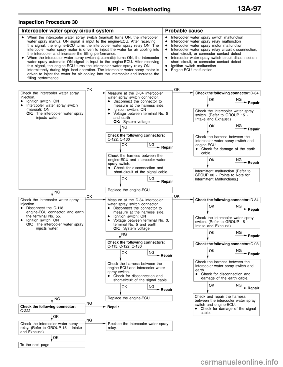
Inspection Procedure 30
Intercooler water spray circuit system
Probable cause
DWhen the intercooler water spray switch (manual) turns ON, the intercooler
water spray manual ON signal is input to the engine-ECU. After receiving
this signal, the engine-ECU turns the intercooler water spray relay ON. The
intercooler water spray motor is driven to inject the water for air cooling into
the intercooler and increase the filling performance.
DWhen the intercooler water spray switch (automatic) turns ON, the intercooler
water spray automatic ON signal is input to the engine-ECU. After receiving
this signal, the engine-ECU turns the intercooler water spray relay ON
intermittently during high - load operation. The intercooler water spray motor is
driven to inject the water for air cooling into the intercooler and increase the
filling performance.DIntercooler water spray switch malfunction
DIntercooler water spray relay malfunction
DIntercooler water spray motor malfunction
DIntercooler water spray relay circuit disconnection,
short - circuit, or connector contact defect
DIntercooler water spray switch circuit disconnection,
short - circuit, or connector contact defect
DIgnition switch malfunction
DEngine-ECU malfunction
NG
Repair OK
Replace the engine-ECU.
OK
NGOK
NG
Repair OK
Check the following connector:D-34
Check the intercooler water spray
switch. (Refer to GROUP 15 -
Intake and Exhaust.)
Check the intercooler water spray
injection.
DIgnition switch: ON
DIntercooler water spray switch
(manual): ON
OK:The intercooler water spray
injects water.
NG
Repair OK
Measure at the D-34 intercooler
water spray switch connector.
DDisconnect the connector to
measure at the harness side.
DIgnition switch: ON
DVoltage between terminal No. 5
and earth
OK:System voltage
NG
OK
Check the harness between the
engine-ECU and intercooler water
spray switch.
DCheck for disconnection and
short-circuit of the signal cable.
Repair
Intermittent malfunction (Refer to
GROUP 00 - Points to Note for
Intermittent Malfunctions.)
NG
OK
Check the harness between the
intercooler water spray switch and
engine-ECU.
DCheck for damage of the earth
cable.
Repair
NG
Repair OK
Replace the engine-ECU.
OK
NGOK
NG
Repair OK
Check the following connector:D-34
Check the intercooler water spray
switch. (Refer to GROUP 15 -
Intake and Exhaust.)
Check the intercooler water spray
injection.
DDisconnect the C-118
engine-ECU connector, and earth
the terminal No. 55.
DIgnition switch: ON
OK:The intercooler water spray
injects water.
NG
Repair OK
Measure at the D-34 intercooler
water spray switch connector.
DDisconnect the connector to
measure at the harness side.
DIgnition switch: ON
DVoltage between terminal No. 3,
terminal No. 5 and earth
OK:System voltage
NG
OK
Check the harness between the
engine-ECU and intercooler water
spray switch.
DCheck for disconnection and
short-circuit of the signal cable.
Repair
Check and repair the harness
between the intercooler water spray
switch and engine-ECU.
DCheck for damage of the signal
cable.
NG
OK
Check the harness between the
intercooler water spray switch and
earth.
DCheck for disconnection and
damage of the earth cable.
Repair
NG
Repair OK
Check the following connector:C-08
OK
Check the following connector:
C-222NG
Repair
OK
To the next page
NGReplace the intercooler water spray
relay.Check the intercooler water spray
relay. (Refer to GROUP 15 - Intake
and Exhaust.)
NG
Check the following connectors:
C-122, C-130
Check the following connectors:
C-115, C-122, C-130NG