2007 MITSUBISHI LANCER EVOLUTION check engine light
[x] Cancel search: check engine lightPage 841 of 1449

MANUAL TRANSMISSION - Troubleshooting
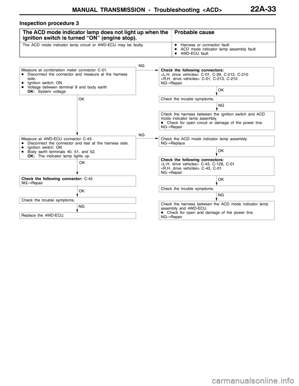
Inspection procedure 3
The ACD mode indicator lamp does not light up when the
ignition switch is turned “ON” (engine stop).
Probable cause
The ACD mode indicator lamp circuit or 4WD-ECU may be faulty.DHarness or connector fault
DACD mode indicator lamp assembly fault
D4WD-ECU fault
OK OK OKOK
NG
OK
NG
NG
NG
Check the harness between the ACD mode indicator lamp
assembly and 4WD-ECU.
DCheck for open and damage of the power line.
NG→Repair
Replace the 4WD-ECU.
Measure at 4WD-ECU connector C-43.
DDisconnect the connector and test at the harness side.
DIgnition switch: ON
DBody earth terminals 40, 51, and 52.
OK:The indicator lamp lights up.
Check the trouble symptoms.
Measure at combination meter connector C-01.
DDisconnect the connector and measure at the harness
side.
DIgnition switch: ON
DVoltage between terminal 9 and body earth
OK:System voltageCheck the following connectors:
NG→Repair
Check the trouble symptoms.
Check the ACD mode indicator lamp assembly.
NG→Replace
Check the harness between the ignition switch and ACD
mode indicator lamp assembly.
DCheck for open circuit or damage of the power line.
NG→Repair
Check the following connectors:
NG→Repair
OK
NG
Check the trouble symptoms.
Check the following connector:C-43
NG→Repair
Page 960 of 1449

REAR AXLE -Troubleshooting
INSPECTION CHART FOR TROUBLE SYMPTOMS
Trouble symptomInspection
procedure No.Reference
page
Communication between MUT-IIand the whole system is not possible.1Refer to
GROUP22
Communication between MUT-IIand 4WD-ECU is not possible.2
GROUP22.
3 ACD mode indicator lamps do not light up when the ignition key is turned to “ON”
(engine stationary).3
3 ACD mode indicator lamps remain lit up after the engine has started.4
AYC is inoperative.
Unable to start or accelerate on slippery road surfaces.527B-14
Rear tires are noisy during low-speed cornering.
Vehicle skews.627B-15
Noise is produced from the torque transfer differential during turning.727B-15
INSPECTION PROCEDURE FOR TROUBLE SYMPTOMS
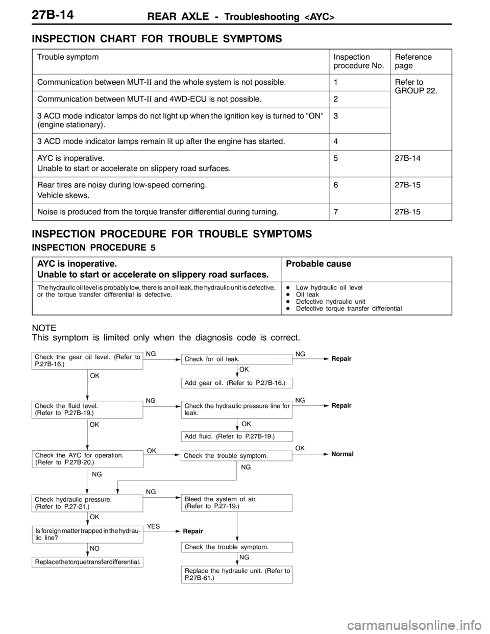
INSPECTION PROCEDURE 5
AYC is inoperative.
Unable to start or accelerate on slippery road surfaces.
Probable cause
The hydraulic oil level is probably low, there is an oil leak, the hydraulic unit is defective,
or the torque transfer differential is defective.DLow hydraulic oil level
DOil leak
DDefective hydraulic unit
DDefective torque transfer differential
NOTE
This symptom is limited only when the diagnosis code is correct.
NG
Replace the hydraulic unit. (Refer to
P.27B-61.)
NG
Add fluid. (Refer to P.27B-19.)
OKRepair
Check the trouble symptom.NO
Replace the torque transfer differential.
OK
Is foreign matter trapped in the hydrau-
lic line?YES
Repair
OK
Check the fluid level.
(Refer to P.27B-19.)Check the hydraulic pressure line for
leak.
OK
Add gear oil. (Refer to P.27B-16.)
OK
Check hydraulic pressure.
(Refer to P.27-21.)NGBleed the system of air.
(Refer to P.27-19.)
Check the gear oil level. (Refer to
P.27B-16.)NGCheck for oil leak.NG
Repair
Check the AYC for operation.
(Refer to P.27B-20.)Check the trouble symptom. OKOK
NGNormal
NGNG
Page 970 of 1449

REAR AXLE -On-vehicle Service27B-24
Torque transfer mechanism part
1. Remove the drive shaft. (Refer to P. 27B-29.)
2. Remove the oil seal from the differential carrier.
3. Using the special tool, drive a new oil seal all the way
into position.
4. Coat the oil seal lips and the drive shaft surface in contact
with the oil seal with the specified grease.
Specified grease: Vaseline
5. Replace the drive shaft circlip with a new one and mount
the drive shaft to the differential carrier. (Refer to P.
27B-29.)
6. Check for correct wheel alignment. (Refer to GROUP
34 – On-vehicle Service.)
ACTION WHEN BATTERY RUNS OUT
When the engine is started using a booster cable where the
battery has completely run down and you attempt to start
the vehicle without waiting for the battery to recover a certain
charge, the engine can misfire and you just cannot start to
move it. In such cases, charge the battery sufficiently; or,
remove the AYC battery cable from the battery fuse assembly
to make AYC inactive before attempting to start the vehicles.
When the battery cable is removed, the ACD mode indicator
lamp lights up. After the battery has been recharged, fit the
battery cable back again and start the engine to ensure that
the ACD mode indicator lamp is off.
MD998829
MD998813 MD998812
Battery fuse assembly
Battery cable
for AYC
Page 1050 of 1449

BASIC BRAKE SYSTEM -On-vehicle Service35A-8
2. If the brake pedal play is not within the standard value,
check the following, and adjust or replace if necessary:
DExcessive play between the brake pedal and the clevis
pin, or between the clevis pin and the brake booster
operating rod
DBrake pedal height
DInstallation position of the stop lamp switch, etc.
CLEARANCE BETWEEN BRAKE PEDAL AND FLOOR
BOARD
1. Turn up the carpet etc. under the brake pedal.
2. Start the engine, depress the brake pedal with
approximately 500 N of force, and measure the clearance
between the brake pedal and the floorboard.
Standard value (C): 90 mm or more
3. If the clearance is outside the standard value, check for
air trapped in the brake line and thickness of the disc
brake pad and dragging in the parking brake.
Adjust and replace defective parts as required.
4. Return the carpet, etc.
BRAKE BOOSTER OPERATING TEST
For simple checking of the brake booster operation, carry
out the following tests:
1. Run the engine for one or two minutes, and then stop
it.
If the pedal depresses fully the first time but gradually
becomes higher when depressed succeeding times, the
booster is operating properly. If the pedal height remains
unchanged, the booster is defective.
2. With the engine stopped, step on the brake pedal several
times.
Then start the engine while the brake pedal is stepped
on.
If the pedal moves downward slightly, the booster is in
good condition. If there is no change, the booster is
defective.
3. With the engine running, step on the brake pedal and
then stop the engine.
Hold the pedal depressed for 30 seconds. If the pedal
height does not change, the booster is in good condition.
If the pedal rises, the booster is defective.
If the above three tests are okay, the booster performance
can be determined as good.
If one of the above three tests is not okay at least, the check
valve, vacuum hose, or booster will be defective.
C
Good No good
When engine is
stoppedWhen engine is
started
GoodNo good
Page 1121 of 1449

STEERING -On-vehicle Service37A-7
ON-VEHICLE SERVICE
STEERING WHEEL FREE PLAY CHECK
1. With engine running (hydraulic operation), set front wheels
straight ahead.
2. Measure the play on steering wheel circumference before
wheels start to move when slightly moving steering wheel
in both directions.
Limit: 30 mm or less
3. When play exceeds the limit, check for play on steering
shaft connection and steering linkage. Correct or replace.
4. If the free play still exceeds the limit value, set steering
wheel straight ahead with engine stopped. Load 5 N
towards steering wheel circumference and check play.
Standard value: 0 - 10 mm
5. If the play exceeds the standard value, remove steering
gear box and check total pinion torque. (Refer to
P.37A-17.)
STEERING ANGLE CHECK
1. Locate front wheels on turning radius gauge and measure
steering angle.
Standard value:
Inner wheel31_45’±1_30’
Outer wheel
2. When the angle is not within the standard value, the
toe-in is probably incorrect. Adjust the toe-in.
Standard value: 0±2mm
Adjust the toe-in by undoing the clip and lock nut, and
turning the left and right tie rod turnbuckles by the same
amount (in opposite directions).
3. Recheck the steering angle.
TIE ROD END BALL JOINT TURNING TORQUE
CHECK
1. Disconnect tie rod and knuckle with special tool.
Caution
(1) Loosen the nut of the special tool, but do not
remove it. If it is removed, the ball joint thread
may be damaged.
(2) Tie the special tool with a cord so as not to fall
off.
Clip
Lock nut
Cord
Ball jointNutMB990635,
MB991113 or
MB991406
Page 1348 of 1449

CHASSIS ELECTRICAL -Headlamp Assembly54A-28
HEADLAMP INTENSITY MEASUREMENT
1. Using a photometer, and following its manufacture’s
instruction manual.
2. Maintain an engine speed of 2,000 r/min., with the battery
in the charging condition
3. Set the headlamps to high beam
4. Measure the headlamp centre intensity (a point of H line
and V line) and check to be sure that the limit value
is satisfied.
Limit:
High beam 30,000 cd or more per one headlamp
NOTE
1. There may be special local regulations pertaining to
headlamp intensity, be sure to make any adjustments
necessary to satisfy such regulations.
2. If an illuminometer is used to make the measurements,
convert its values to photometer values by using the
following formula.
I=Er
2Where:
I=intensity (cd)
E=illumination (lux)
r=distance (m) from headlamps to illuminometer
Caution
1. On the headlamp not yet adjusted, perform aiming
with connector removed and the lamps switched off,
if applicable. In addition, care should be taken to
prevent a change of optical axis when connector is
reconnected.
2. Plastic outer lens are equipped with headlamps. When
lens surface is covered with materials for not
penetrating light, headlamp operation time should be
within 3 minutes. In addition, masking such as taping
should not be performed.
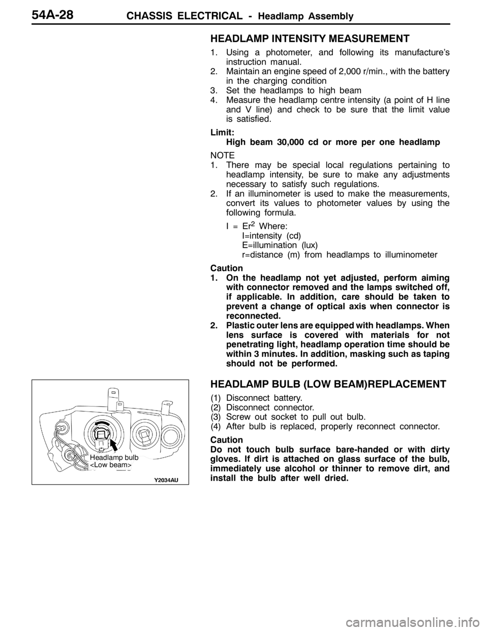
HEADLAMP BULB (LOW BEAM)REPLACEMENT
(1) Disconnect battery.
(2) Disconnect connector.
(3) Screw out socket to pull out bulb.
(4) After bulb is replaced, properly reconnect connector.
Caution
Do not touch bulb surface bare-handed or with dirty
gloves. If dirt is attached on glass surface of the bulb,
immediately use alcohol or thinner to remove dirt, and
install the bulb after well dried.
Headlamp bulb
Page 1414 of 1449

HEATER, AIR CONDITIONER AND VENTILATION-TroubleshootingHEATER, AIR CONDITIONER AND VENTILATION-Troubleshooting55-12
CHECK AT THE ENGINE-ECU TERMINAL
Terminal no.Check itemCheck whenNormal state
21Fan controller outputRadiator fan: ON0 - 0.3 Vp
Radiator fan: OFF0.7 V or more
22A/C compressor outputA/C compressor relay: OFF0Vpp
A/C compressor relay: ONBattery voltage
or temporarily
6V or more→
1V or less
24A/C-ECU input (A/C2)At A/C low loadBattery voltage
32Condenser fan motor relay (HI)Fan: OFF(engine coolant temperature:90_C
or lower)Battery voltage
Fan: ON(engine coolant tempera-
ture:105_C or lower)1V or more
34Condenser fan motor relay (LOW)Fan: OFF(engine coolant temperature:90_C
or lower)Battery voltage
Fan: ON(engine coolant tempera-
ture:105_C or lower)1V or more
45A/C-ECU input (A/C1)A/C ON (When dual pressure switch is ON)Battery voltage
CHECK AT THE A/C-ECU TERMINAL
Termi-
nal no.Check itemCheck whenNormal state
1Rear defogger switchDefogger switch: ON0Vgg
Defogger switch: OFFBattery voltage
2Inside/outside air changeover
dt(tidi)
When damper moved to inside circulation position0Vg
damper motor (outside air)When damper moved to outside air induction
positionBattery voltage
3Inside/outside air changeover
dt(i idi)
When damper moved to inside circulation positionBattery voltageg
damper motor (inside air)When damper moved to outside air induction
position0V
4Engine-ECU output (A/C1)When A/C OFF0Vgp()
A/C switch: ON, blower: ON (room temperature)Battery voltage
5Engine-ECU output (A/C2)At A/C low loadBattery voltagegp()
At A/C high load0V
6Illumination power supplyLighting switches: ONBattery voltage
7---
8Blower switch (LO)Blower switch: LOBattery voltage
Page 1415 of 1449

HEATER, AIR CONDITIONER AND VENTILATION-Troubleshooting55-13
Termi-
nal no.Normal state Check when Check item
9---
10Ignition switch (IG2) power supplyIgnition switch: ONBattery voltage
11Illumination earthAny time0V
12EarthAny time0V
13Air thermo sensorWhen temperature around sensor 25_C (1.5kΩ)2.2 V
14---
15---
16Air thermo sensor earthAny time0V
CHECK AT THE A/C-ECU TERMINAL
Termi-
nal no.Check itemCheck whenNormal state
1Engine-ECU output (A/C1)When A/C OFF0Vgp()
A/C switch: ON, blower: ON (room temperature)Battery voltage
2Engine-ECU output (A/C2)At A/C low loadBattery voltagegp()
At A/C high load0V
3EarthAny time0V
4Air thermo sensor earthAny time0V
5Illumination power supplyLighting switches: ONBattery voltage
6Air thermo sensorWhen temperature around sensor 25_C (1.5kΩ)2.2 V
7Ignition switch (IG2) power supplyIgnition switch: ONBattery voltage
8Blower switch (LO)Blower switch: LOBattery voltage
9Rear defogger switchDefogger switch: ON0Vgg
Defogger switch: OFFBattery voltage
10Inside/outside air changeover
dt(tidi)
When damper moved to inside circulation position0Vg
damper motor (outside air)When damper moved to outside air induction
positionBattery voltage
11Inside/outside air changeover
dt(i idi)
When damper moved to inside circulation positionBattery voltageg
damper motor (inside air)When damper moved to outside air induction
position0V
12Illumination earthAny time0V