2007 MITSUBISHI LANCER EVOLUTION check engine light
[x] Cancel search: check engine lightPage 643 of 1449

MPI -Troubleshooting13A-111
Terminal No.Normal condition Check condition (Engine condition) Check item
37Power steering fluid
pressure switchEngine: Idling after
warming upWhen steering wheel
is stationarySystem voltage
When steering wheel
is turned1 V or less
38Engine control relayIgnition switch: “LOCK” (OFF)System voltage
Ignition switch: “ON”1 V or less
39Fuel pump relay 3While engine is idling, suddenly depress the
accelerator pedal.Temporarily rises slightly
from 1 V or less.
41Alternator FR
terminalDEngine: After warm-up, idle operation
DRadiator fan: Not operating
DHead lamp: OFF→ON
DStop lamp: OFF→ON
DRear deffogger switch: OFF→ONVoltage decrease
44Intercooler water
spray switch (Auto)DIgnition switch: “ON”
DIntercooler water spray switch: ON1 V or less
DIgnition switch: “ON”
DIntercooler water spray switch: OFFSystem voltage
45A/C switchEngine: Idle operationTurn the A/C switch
OFF0.5 V or less
DA/C switch: ON
DA/C setting
temperature
When room tem-
perature is 25_C
or more: Max
Cool
When room tem-
perature is 25_C
or less: Max. HotSystem voltage
53Secondary air control
solenoid valveIgnition switch: “ON”System voltage
54Oxygen sensor
heater(Rear)
Engine: Idling after warming up1 V or less
heater(Rear)
Engine speed: 5,000r/minSystem voltage
55Intercooler water
sprayrelay
Ignition switch: “ON”System voltage
spray relay
Ignition switch: “LOCK” (OFF)1 V or less
58Tachometer signalEngine speed: 3,000r/min0.3 - 3.0 V
60Oxygen sensor
heater(front)
Engine: Idling after warming up1 V or less
heater(front)
Engine speed: 5,000r/minSystem voltage
71Ignition switch - STEngine: Cranking8 V or more
Page 654 of 1449

MPI -Troubleshooting13A-122
Wave Pattern Observation Points
Check that the standard wave pattern appears when the stepper motor is operating.
Point A: Presence or absence of induced electromotive force from the motor turning. (Refer to the abnormal
wave pattern.)
Contrast with standard wave patternProbable cause
Induced electromotive force does not appear or is extremely small.Motor is malfunctioning
Point B: Height of coil reverse electromotive force
Contrast with standard wave patternProbable cause
Coil reverse electromotive force does not appear or is extremely small.Short in the coil
Examples of Abnormal Wave Pattern
DExample 1
Cause of problem
Motor is malfunctioning. (Motor is not operating.)
Wave pattern characteristics
Induced electromotive force from the motor turning does
not appear.
DExample 2
Cause of problem
Open circuit in the line between the stepper motor and
the engine-ECU.
Wave pattern characteristics
Current is not supplied to the motor coil on the open
circuit side. (Voltage does not drop to 0 V.)
Furthermore, the induced electromotive force waveform
at the normal side is slightly different from the normal
waveform.
Open
circuit
side
Normal
side
Page 660 of 1449

MPI -On-vehicle Service13A-128
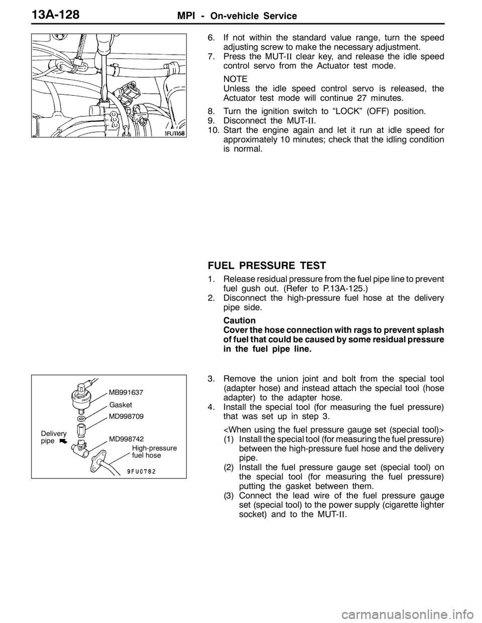
6. If not within the standard value range, turn the speed
adjusting screw to make the necessary adjustment.
7. Press the MUT-IIclear key, and release the idle speed
control servo from the Actuator test mode.
NOTE
Unless the idle speed control servo is released, the
Actuator test mode will continue 27 minutes.
8. Turn the ignition switch to “LOCK” (OFF) position.
9. Disconnect the MUT-II.
10. Start the engine again and let it run at idle speed for
approximately 10 minutes; check that the idling condition
is normal.
FUEL PRESSURE TEST
1. Release residual pressure from the fuel pipe line to prevent
fuel gush out. (Refer to P.13A-125.)
2. Disconnect the high-pressure fuel hose at the delivery
pipe side.
Caution
Cover the hose connection with rags to prevent splash
of fuel that could be caused by some residual pressure
in the fuel pipe line.
3. Remove the union joint and bolt from the special tool
(adapter hose) and instead attach the special tool (hose
adapter) to the adapter hose.
4. Install the special tool (for measuring the fuel pressure)
that was set up in step 3.
(1) Install the special tool (for measuring the fuel pressure)
between the high-pressure fuel hose and the delivery
pipe.
(2) Install the fuel pressure gauge set (special tool) on
the special tool (for measuring the fuel pressure)
putting the gasket between them.
(3) Connect the lead wire of the fuel pressure gauge
set (special tool) to the power supply (cigarette lighter
socket) and to the MUT-II.
MB991637
Gasket
MD998709
MD998742
High-pressure
fuel hose
Delivery
pipe
Page 661 of 1449

MPI -On-vehicle Service13A-129
(1) Install the fuel pressure gauge on the special tool
(for measuring the fuel pressure) putting a suitable
O-ring or gasket between them.
(2) Install the special tool which was set up in step (1)
between the high-pressure fuel hose and the delivery
pipe.
5. Connect the MUT-IIto the diagnosis connector.
6. Turn the ignition switch to “ON” position. (But do not start
the engine.)
7. Select “Item No. 07” from the MUT-IIActuator test to
drive the fuel pump. Check that there are no fuel leaks
from any parts.
8. Finish the actuator test or turn the ignition switch to “LOCK”
(OFF) position.
9. Start the engine and run at idle.
10. Measure fuel pressure while the engine is running at
idle.
Standard value: Approximately 230 kPa at cerb idle
11. Disconnect the vacuum hose from the fuel pressure
regulator and measure fuel pressure with the hose end
closed by a finger.
Standard value: 289 - 309 kPa at cerb idle
12. Check to see that fuel pressure at idle does not drop
even after the engine has been raced several times.
13. Racing the engine repeatedly, hold the fuel return hose
lightly with fingers to feel that fuel pressure is present
in the return hose.
NOTE
If the fuel flow rate is low, there will be no fuel pressure
in the return hose.Fuel pressure gauge set
O-ring or gasket
MD998709
MD998742
High-pressure
fuel hose
Delivery
pipe
Page 737 of 1449

ENGINE ELECTRICAL -Charging System16-5
(6) Reconnect the negative battery cable.
(7) Connect a tachometer or the MUT-II.
(Refer to GROUP 11 - On-vehicle Service.)
(8) Leave the hood open.
(9) Start the engine.
(10)With the engine running at 2,500 r/min, turn
the headlamps and other lamps on and off
to adjust the alternator load so that the value
displayed on the ammeter is slightly above 30
A.
Adjust the engine speed by gradually
decreasing it until the value displayed on the
ammeter is 30 A. Take a reading of the value
displayed on the voltmeter at this time.
Limit: max. 0.3 V
NOTE
When the alternator output is high and the value
displayed on the ammeter does not decrease
until 30 A, set the value to 40 A. Read the
value displayed on the voltmeter at this time.
When the value range is 40 A, the limit is max.
0.4 V.(11) If the value displayed on the voltmeter is above
the limit value, there is probably a malfunction
in the alternator output wire, so check the wiring
between the alternator “B” terminal and the
battery (+) terminal (including fusible link).
If a terminal is not sufficiently tight or if the
harness has become discolored due to
overheating, repair and then test again.
(12)After the test, run the engine at idle.
(13)Turn off all lamps and the ignition switch.
(14)Remove the tachometer or the MUT-II.
(15)Disconnect the negative battery cable.
(16)Disconnect the ammeter and voltmeter.
(17)Connect the alternator output wire to the
alternator “B” terminal.
(18)Connect the negative battery cable.
OUTPUT CURRENT TEST
Charging warning lampVoltmeter
Ammeter
Ignition switch
Alternator relayLoad
Battery
Engine-ECUAlternatorFR
L
S
G
+ -+-
B
Page 738 of 1449

ENGINE ELECTRICAL -Charging System16-6
This test determines whether the alternator output
current is normal.
(1) Before the test, always be sure to check the
following.
DAlternator installation
DBattery (Refer to GROUP 54 - Battery.)
NOTE
The battery should be slightly discharged.
The load needed by a fully-charged battery
is insufficient for an accurate test.
DAlternator drive belt tension
(Refer to GROUP 11 - On-vehicle Service.)
DFusible link
DAbnormal noise from the alternator while
the engine is running.
(2) Turn the ignition switch to the “LOCK” (OFF)
position.
(3) Disconnect the negative battery cable.
(4) Disconnect the alternator output wire from the
alternator “B” terminal. Connect a DC test
ammeter with a range of 0 - 100 A in series
between the “B” terminal and the disconnected
output wire. (Connect the (+) lead of the
ammeter to the “B” terminal. Connect the ( - )
lead of the ammeter to the disconnected output
wire.)
Caution
Never use clips but tighten bolts and nuts
to connect the line. Otherwise loose
connections (e.g. using clips) will lead to
a serious accident because of high current.
NOTE
An inductive-type ammeter which enables
measurements to be taken without
disconnecting the alternator output wire should
be recommended.
(5) Connect a voltmeter with a range of 0 - 20 V
between the alternator “B” terminal and the
earth. (Connect the (+) lead of the voltmeter
to the “B” terminal, and then connect the ( - )
lead of the voltmeter to the earth.)
(6) Connect the negative battery cable.
(7) Connect a tachometer or the MUT-II.
(Refer to GROUP 11 - On-vehicle Service.)
(8) Leave the hood open.
(9) Check that the reading on the voltmeter is equal
to the battery voltage.
NOTE
If the voltage is 0 V, the cause is probably
an open circuit in the wire or fusible link between
the alternator “B” terminal and the battery (+)
terminal.(10)Turn the light switch on to turn on headlamps
and then start the engine.
(11) Immediately after setting the headlamps to high
beam and turning the heater blower switch to
the high revolution position, increase the engine
speed to 2,500 r/min and read the maximum
current output value displayed on the ammeter.
Limit: 70 % of normal current output
NOTE
DFor the nominal current output, refer to the
Alternator Specifications.
DBecause the current from the battery will
soon drop after the engine is started, the
above step should be carried out as quickly
as possible in order to obtain the maximum
current output value.
DThe current output value will depend on
the electrical load and the temperature of
the alternator body.
DIf the electrical load is small while testing,
the specified level of current may not be
output even though the alternator is normal.
In such cases, increase the electrical load
by leaving the headlamps turned on for
some time to discharge the battery or by
using the lighting system in another vehicle,
and then test again.
DThe specified level of current also may not
be output if the temperature of the alternator
body or the ambient temperature is too
high. In such cases, cool the alternator and
then test again.
(12)The reading on the ammeter should be above
the limit value. If the reading is below the limit
value and the alternator output wire is normal,
remove the alternator from the engine and
check the alternator.
(13)Run the engine at idle after the test.
(14)Turn the ignition switch to the “LOCK” (OFF)
position.
(15)Remove the tachometer or the MUT-II.
(16)Disconnect the negative battery cable.
(17)Disconnect the ammeter and voltmeter.
(18)Connect the alternator output wire to the
alternator “B” terminal.
(19)Connect the negative battery cable.
Page 776 of 1449

ENGINE AND EMISSION CONTROL -Emission Control System17-6
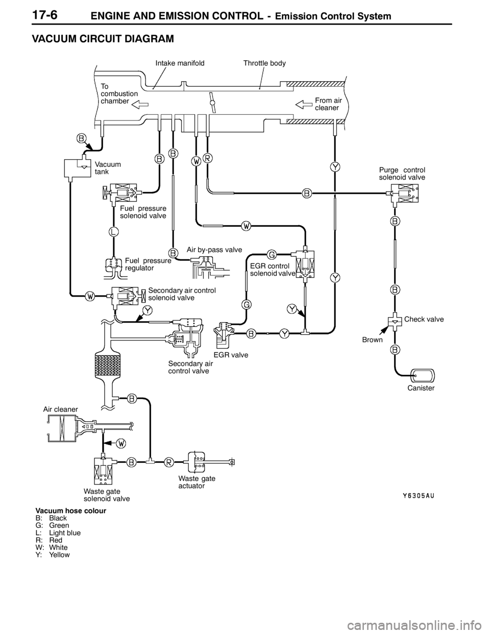
VACUUM CIRCUIT DIAGRAM
Vacuum hose colour
B: Black
G: Green
L: Light blue
R: Red
W: White
Y: YellowFrom air
cleaner
Intake manifoldThrottle body
To
combustion
chamber
Fuel pressure
regulator
EGR control
solenoid valve
Canister
EGR valve
Brown
Check valve Vacuum
tank
Fuel pressure
solenoid valve
Air by-pass valve
Secondary air control
solenoid valve
Secondary air
control valvePurge control
solenoid valve
Air cleaner
Waste gate
solenoid valveWaste gate
actuator
Page 839 of 1449

MANUAL TRANSMISSION - Troubleshooting
INSPECTION CHART FOR TROUBLE SYMPTOMS
Trouble symptomInspection
procedure No.Reference
page
No communication possible between MUT-IIand all systems.122A-31
No communication possible between MUT-IIand 4WD-ECU.222A-32
ACD mode indicator lamp does not light up when the ignition switch is set to ”ON“
(engine is stopped).322A-33
More than two ACD mode indicator lamps remain lit even after the engine is started422A-34
The ACD does not operate (no diagnostic code).522A-34
The AYC does not operate (no diagnostic code).6Refer to
GROUPThe rear tire sounds when turning at low speed corners (vehicle slows down)7GROUP
27B.
Noise is produced from the torque transfer differential during turning.8
27B.
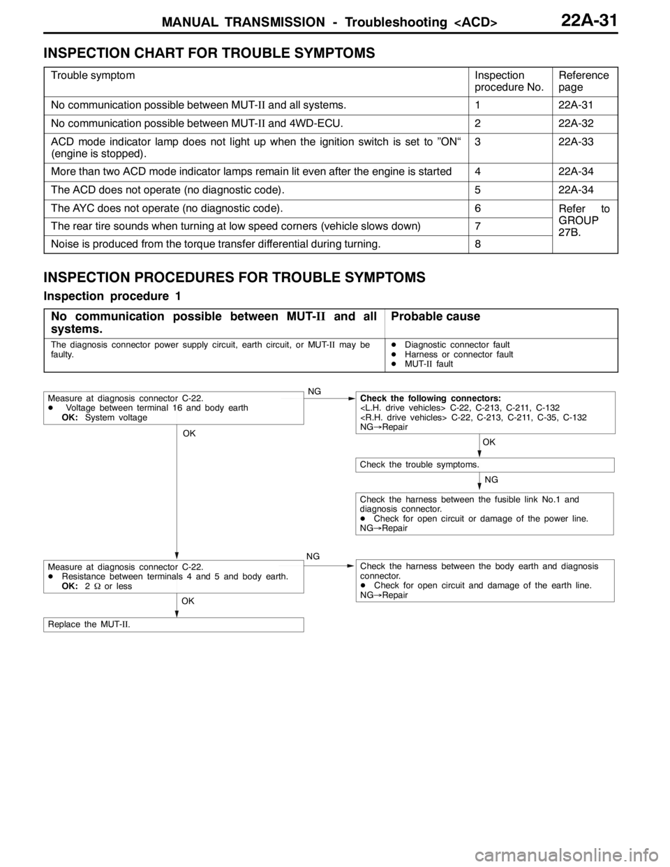
INSPECTION PROCEDURES FOR TROUBLE SYMPTOMS
Inspection procedure 1
No communication possible between MUT-IIand all
systems.
Probable cause
The diagnosis connector power supply circuit, earth circuit, or MUT-IImay be
faulty.DDiagnostic connector fault
DHarness or connector fault
DMUT-IIfault
OK
NG
NG
Check the harness between the fusible link No.1 and
diagnosis connector.
DCheck for open circuit or damage of the power line.
NG→Repair
OK
Check the trouble symptoms.
Measure at diagnosis connector C-22.
DVoltage between terminal 16 and body earth
OK:System voltageNGCheck the following connectors:
NG→Repair
Check the harness between the body earth and diagnosis
connector.
DCheck for open circuit and damage of the earth line.
NG→Repair
OK
Replace the MUT-II.
Measure at diagnosis connector C-22.
DResistance between terminals 4 and 5 and body earth.
OK:2Ωor less