Page 1030 of 1449

FRONT SUSPENSION -Special Tools/On-vehicle Service33A-4
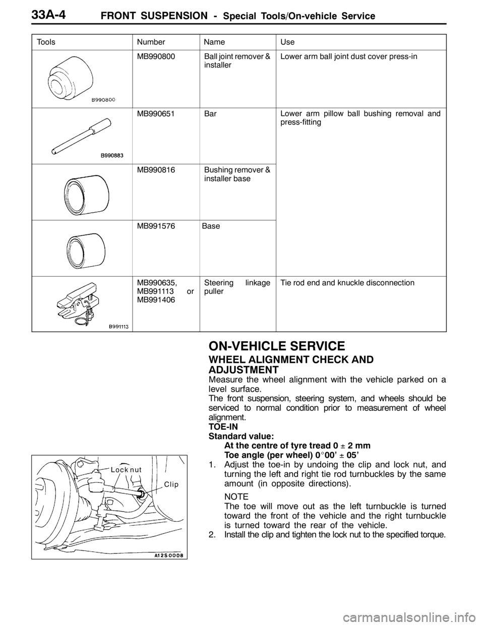
Tools UseName Number
MB990800Ball joint remover &
installerLower arm ball joint dust cover press-in
MB990651BarLower arm pillow ball bushing removal and
press-fitting
MB990816Bushing remover &
installer base
MB991576Base
MB990635,
MB991113 or
MB991406Steering linkage
pullerTie rod end and knuckle disconnection
ON-VEHICLE SERVICE
WHEEL ALIGNMENT CHECK AND
ADJUSTMENT
Measure the wheel alignment with the vehicle parked on a
level surface.
The front suspension, steering system, and wheels should be
serviced to normal condition prior to measurement of wheel
alignment.
TOE-IN
Standard value:
At the centre of tyre tread 0±2mm
Toe angle (per wheel) 0_00’±05’
1. Adjust the toe-in by undoing the clip and lock nut, and
turning the left and right tie rod turnbuckles by the same
amount (in opposite directions).
NOTE
The toe will move out as the left turnbuckle is turned
toward the front of the vehicle and the right turnbuckle
is turned toward the rear of the vehicle.
2. Install the clip and tighten the lock nut to the specified torque.
Clip
Lock nut
Page 1031 of 1449

FRONT SUSPENSION -On-vehicle Service33A-5
Tightening torque: 52±2 N·m
3. Confirm that the toe-in is at the standard value.
4. Use a turning radius gauge to check that the steering
angle is at the standard value.
Standard value:
Inner wheels31_45’±1_30’
Outer wheels (for reference)27_15’
TOE-OUT ANGLE ON TURNS
To check the steering linkage, especially after the vehicle
has been involved in an accident or if an accident is presumed,
it is advisable to check the toe-out angle on turns in addition
to the wheel alignment.
Conduct this test on the left turn as well as on the right turn.
Standard value:
ItemsSpecifications
Toe-out angle on turns
(inner wheel when outer wheel at 20_)22_00’±1_30’
CAMBER, CASTER AND KINGPIN INCLINATION
Standard value:
ItemsSpecifications
Camber
(Selectable from 2 options)-1_00’±30’* or - 2_00’±30’*
Caster3_55’±30’*
Kingpin inclination13_45’±1_30’
NOTE
1. *: difference between right and left wheels must be less
than 30’
2. Caster and kingpin inclination are preset at the factory
and cannot be adjusted.
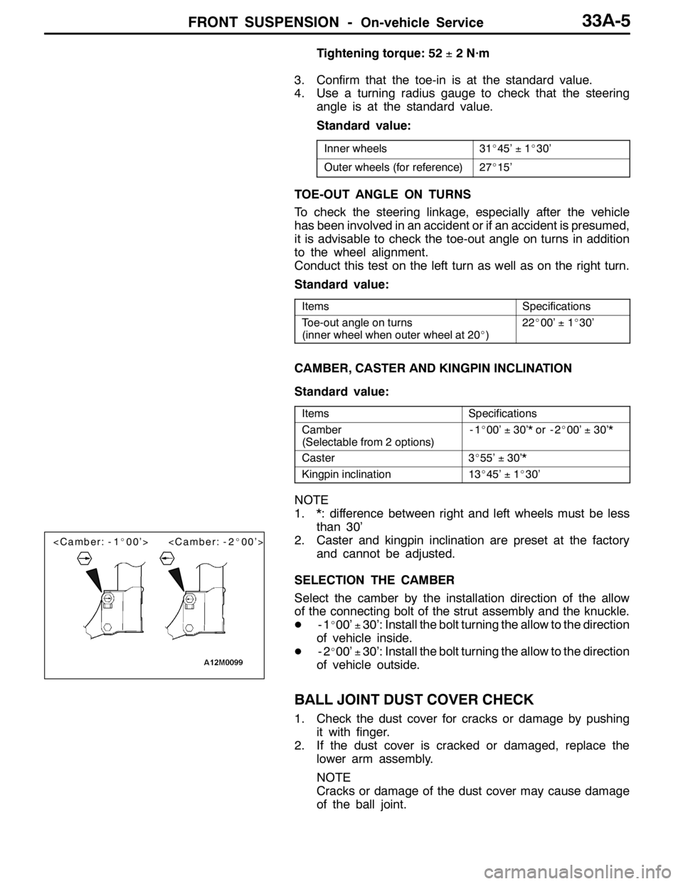
SELECTION THE CAMBER
Select the camber by the installation direction of the allow
of the connecting bolt of the strut assembly and the knuckle.
D-1
_00’±30’: Install the bolt turning the allow to the direction
of vehicle inside.
D-2
_00’±30’: Install the bolt turning the allow to the direction
of vehicle outside.
BALL JOINT DUST COVER CHECK
1. Check the dust cover for cracks or damage by pushing
it with finger.
2. If the dust cover is cracked or damaged, replace the
lower arm assembly.
NOTE
Cracks or damage of the dust cover may cause damage
of the ball joint.
Page 1032 of 1449
FRONT SUSPENSION -Strut Assembly33A-6
STRUT ASSEMBLY
REMOVAL AND INSTALLATION
Post-installation Operation
Wheel alignment check and adjustment (Refer to
P.33A-4.)
44±5N·m
3
21
167±9N·m
4
5
Removal steps
1. Front wheel speed sensor harness
bracket
2. Brake hose bracket3. Knuckle connection
4. Strut mounting nut
5. Strut assembly
Page 1035 of 1449
FRONT SUSPENSION -Lower Arm Assembly33A-9
LOWER ARM ASSEMBLY
REMOVAL AND INSTALLATION
Caution
1. If the vehicle is equipped with the Brembo disc brake, during maintenance, take care not to
contact the parts or tools to the caliper because the paint of caliper will be scratched. And
if there is brake fluid on the caliper, wipe out quickly.
2. *: To prevent bushings from breakage, the parts indicated by * should be temporarily tightened,
and then fully tightened with the vehicle on the ground in the unladen condition.
Post-installation Operation
DCheck the dust cover for cracks or damage by
pushing it with finger.
DWheel alignment check and adjustment
(Refer to P.33A-4.)
72
5
186±10 N·m*
3167±9N·m
5
1
3
4
108±10 N·m
39±5N·m
39±5N·m
Removal steps
1. Stabilizer link nut
2. Lower arm and knuckle connection
AA"3. Lower arm and crossmember
connection4. Stabilizer bracket
5. Lower arm assembly
Page 1039 of 1449

FRONT SUSPENSION -Stabilizer Bar33A-13
Pre-removal Operation
DSteering Wheel and Air Bag Module Assembly
Removal (Refer to GROUP 37A.)
DClock Spring Removal (Refer to GROUP 52B.)
DCrossmember Bar Removal (Refer to P.33A-15.)
DCentermember Removal (Refer to GROUP 32.)
DFront Exhaust Pipe Removal (Refer to GROUP 15.)Post-installation Operation
DFront Exhaust Pipe Installation (Refer to GROUP
15.)
DCentermember Installation (Refer to GROUP 32.)
DCrossmember Bar Installation (Refer to P.33A-15.)
DClock Spring Installation (Refer to GROUP 52B.)
DSteering Wheel and Air Bag Module Assembly
Installation (Refer to GROUP 37A.)
DCheck the Dust Cover for Cracks or Damage by
Pushing it with Finger.
DChecking Steering Wheel Position with Wheels
Straight Ahead
DFront Wheel Alignment Check and Adjustment
(Refer to P.33A-4.)
3
4
10
21±4N·m
51
1
2
25±5N·m
18±2N·m
108±10 N·m
52±7N·m*
49±10 N·m
167±9N·m
7
8
9
6
39±5N·m
39±5N·m
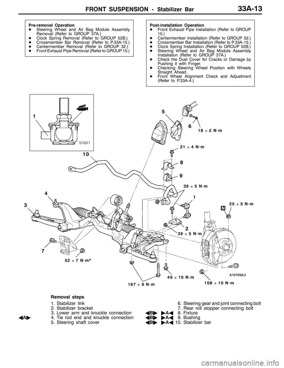
Removal steps
1. Stabilizer link
2. Stabilizer bracket
3. Lower arm and knuckle connection
AA"4. Tie rod end and knuckle connection
5. Steering shaft cover6. Steering gear and joint connecting bolt
7. Rear roll stopper connecting bolt
AB""AA8. Fixture
AB""AA9. Bushing
AB""AA10. Stabilizer bar
Page 1287 of 1449

SRS - SRS Maintenance52B-43
AIR BAG MODULES, STEERING WHEEL AND CLOCK
SPRING AND SEAT BELT WITH PRE-TENSIONER
1. Remove the air bag modules, steering wheel and clock
spring. (Refer to P.52B-52.)
Caution
The removed air bag modules should be stored in
a clean, dry place with the cover face up.
2. Check cover for dents, cracks or deformation.
3. Check connector for damage, terminals deformities, and
harness for binds.
4. Check air bag inflator case for dents, cracks or deformities.
5. Check harness and connectors for damage, and terminals
for deformation.
6. Check clock spring connectors and protective tube for
damage, and terminals for deformation.
7. Visually check the clock spring case for damage.
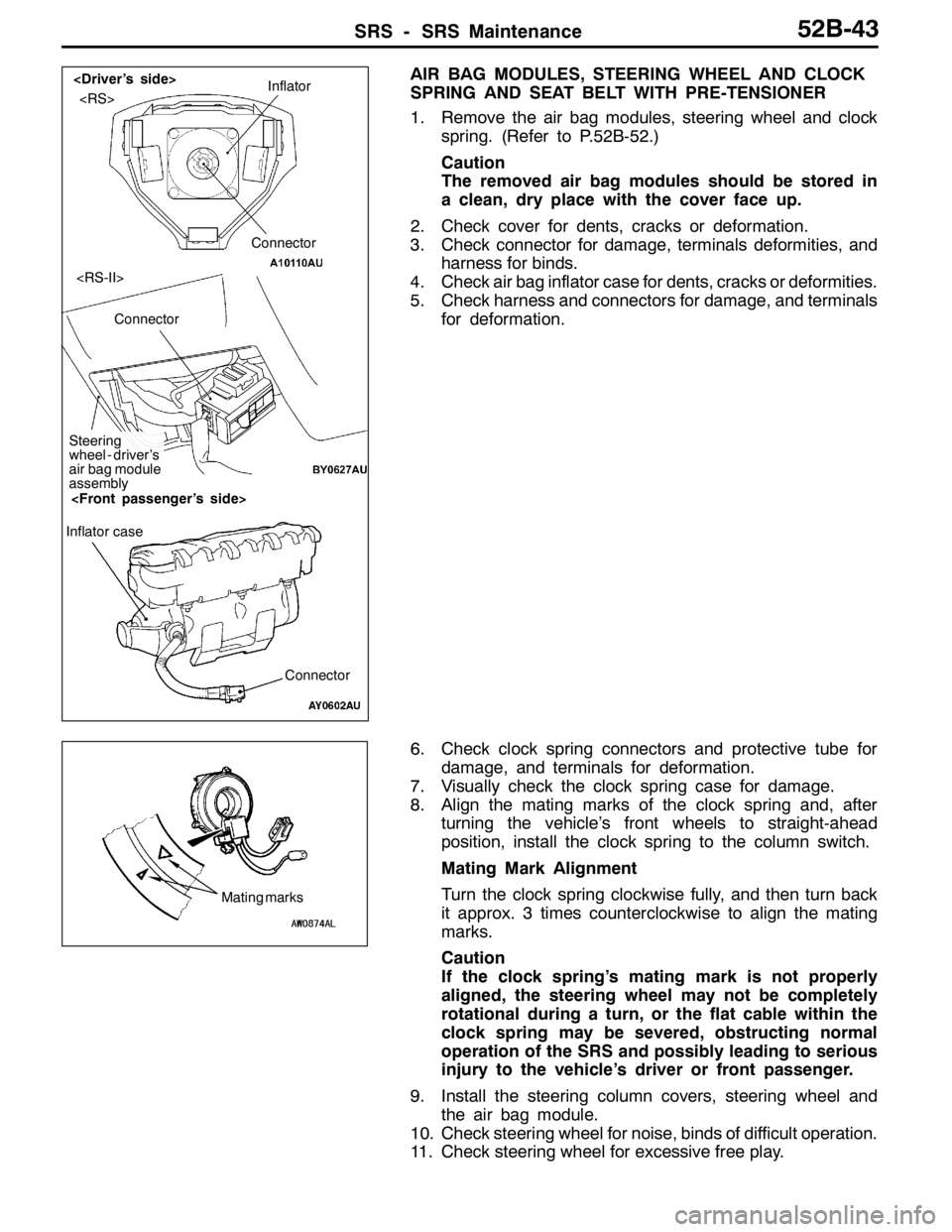
8. Align the mating marks of the clock spring and, after
turning the vehicle’s front wheels to straight-ahead
position, install the clock spring to the column switch.
Mating Mark Alignment
Turn the clock spring clockwise fully, and then turn back
it approx. 3 times counterclockwise to align the mating
marks.
Caution
If the clock spring’s mating mark is not properly
aligned, the steering wheel may not be completely
rotational during a turn, or the flat cable within the
clock spring may be severed, obstructing normal
operation of the SRS and possibly leading to serious
injury to the vehicle’s driver or front passenger.
9. Install the steering column covers, steering wheel and
the air bag module.
10. Check steering wheel for noise, binds of difficult operation.
11. Check steering wheel for excessive free play.Inflator
Connector
Connector
Steering
wheel - driver’s
air bag module
assembly
Connector Inflator case
Mating marks