Page 1014 of 1449

WHEEL AND TYRE -On-vehicle Service/Wheel and Tyre31-6
ON-VEHICLE SERVICE
TYRE INFLATION PRESSURE CHECK
NOTE
For information on tyre inflation pressure, refer to the label
attached near the driver’s side door striker.
TYRE WEAR CHECK
Measure the tread depth of tyres.
Limit: 1.6 mm
If the remaining tread depth is less than the limit, replace
the tyre.
NOTE
When the tread depth of tyres is reduced to 1.6 mm or less,
wear indicators will appear.
WHEEL RUNOUT CHECK
Jack up the vehicle so that the wheels are clear of the floor.
While slowly turning the wheel, measure wheel runout with
a dial indicator.
Limit:
ItemSteel wheelAluminium wheel
Radial runout mm1.21.0
Lateral runout mm1.21.0
If wheel runout exceeds the limit, replace the wheel.
WHEEL AND TYRE
Caution
If the vehicle is equipped with the Brembo disc brake,
during maintenance, take care not to contact the parts
or tools to the caliper because the paint of caliper will
be scratched.
INSTALLATION SERVICE POINT
Tighten the wheel nut to the specified torque.
Tightening torque: 98�¶10 N·m
Radial
Lateral
Page 1053 of 1449

BASIC BRAKE SYSTEM -On-vehicle Service35A-11
BRAKE FLUID LEVEL SENSOR CHECK
The brake fluid level sensor is in good condition if there is
no continuity when the float surface is above “MIN” and if
there is continuity when the float surface is below “MIN”.
DISC BRAKE PAD CHECK AND REPLACEMENT
NOTE
The wear indicator contacts the brake disc when the brake
pad thickness reaches approximately 2 mm and emit a
squealing sound to warn the driver.
1. Check the brake pad thickness through the caliper body
check port.
Standard value: 10.0 mm
Limit: 2.0 mm
2. When the thickness is less than the limit, always replace
the pads at an axle set.
3. Remove the pin bolt. Pivot the caliper assembly and hold
it with wires.
Caution
Do not wipe off the special grease that is on the pin
or allow it to contaminate the pin.
4. Remove the following parts from the caliper support.
1. Pad and wear indicator assembly
2. Pad assembly
3. Clip
4. Outer shim
5. In order to measure the brake drag force after pad
installation, measure the rotary-sliding resistance of the
hub with the pads removed. (Refer to P.35A-21.)
6. Install the pads and caliper assembly, and then check
the brake drag force. (Refer to P.35A-21.)
14Z0017
Front Rear
Front Rear
Front Rear
12 34
3
1
2 3
4
3
Page 1054 of 1449

BASIC BRAKE SYSTEM -On-vehicle Service35A-12
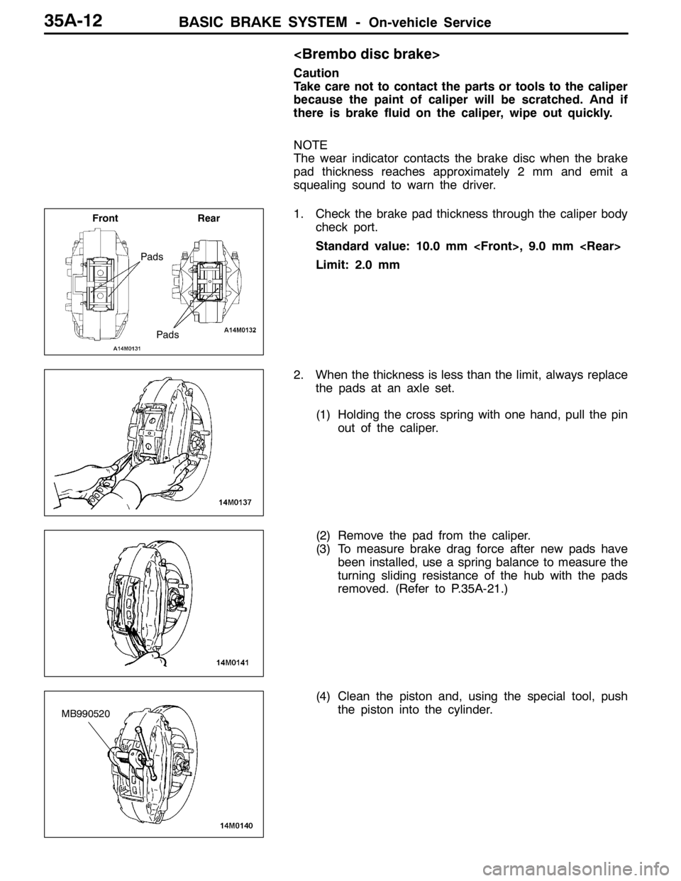
Caution
Take care not to contact the parts or tools to the caliper
because the paint of caliper will be scratched. And if
there is brake fluid on the caliper, wipe out quickly.
NOTE
The wear indicator contacts the brake disc when the brake
pad thickness reaches approximately 2 mm and emit a
squealing sound to warn the driver.
1. Check the brake pad thickness through the caliper body
check port.
Standard value: 10.0 mm , 9.0 mm
Limit: 2.0 mm
2. When the thickness is less than the limit, always replace
the pads at an axle set.
(1) Holding the cross spring with one hand, pull the pin
out of the caliper.
(2) Remove the pad from the caliper.
(3) To measure brake drag force after new pads have
been installed, use a spring balance to measure the
turning sliding resistance of the hub with the pads
removed. (Refer to P.35A-21.)
(4) Clean the piston and, using the special tool, push
the piston into the cylinder.
Pads
Front Rear
Pads
MB990520
Page 1055 of 1449

BASIC BRAKE SYSTEM -On-vehicle Service35A-13
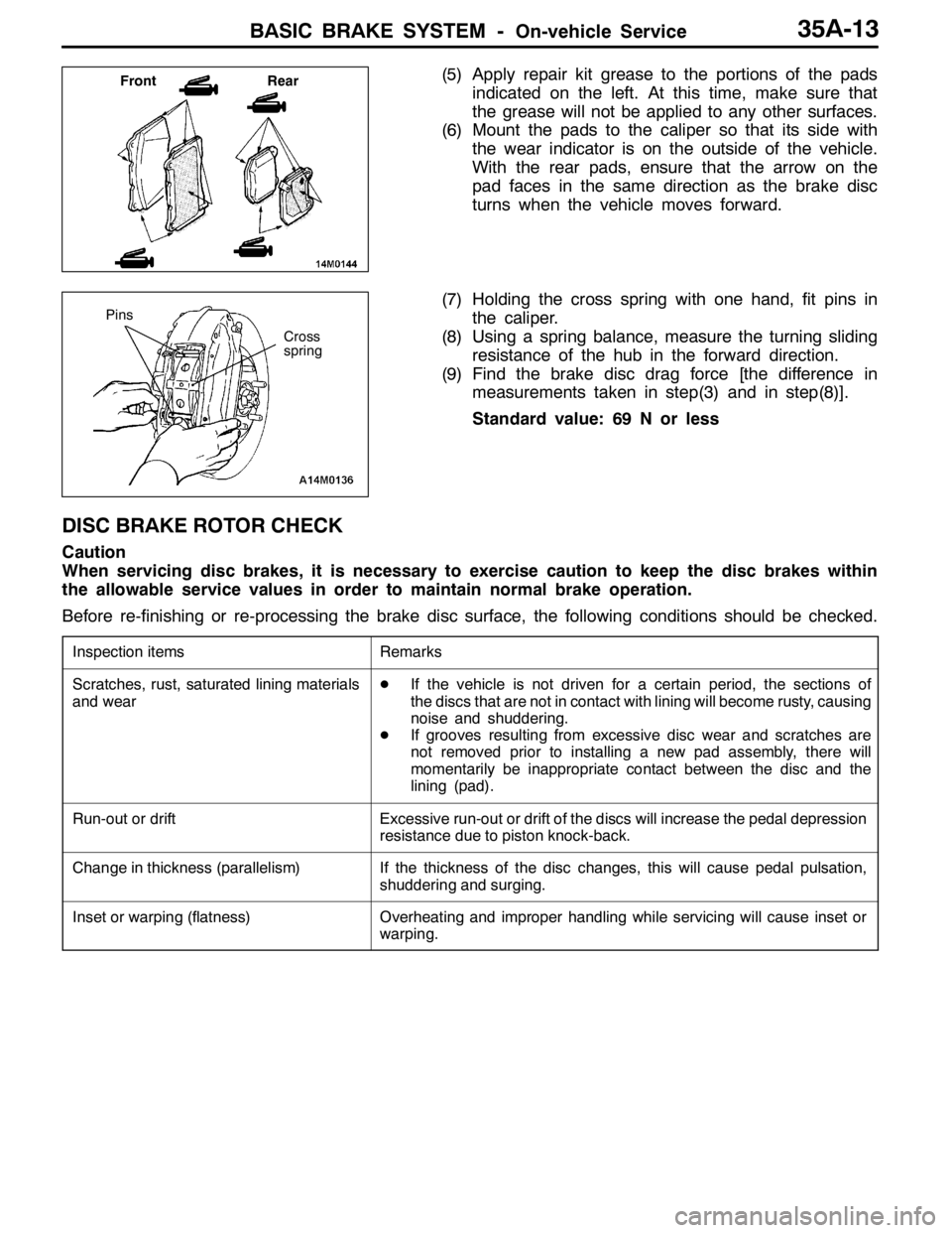
(5) Apply repair kit grease to the portions of the pads
indicated on the left. At this time, make sure that
the grease will not be applied to any other surfaces.
(6) Mount the pads to the caliper so that its side with
the wear indicator is on the outside of the vehicle.
With the rear pads, ensure that the arrow on the
pad faces in the same direction as the brake disc
turns when the vehicle moves forward.
(7) Holding the cross spring with one hand, fit pins in
the caliper.
(8) Using a spring balance, measure the turning sliding
resistance of the hub in the forward direction.
(9) Find the brake disc drag force [the difference in
measurements taken in step(3) and in step(8)].
Standard value: 69 N or less
DISC BRAKE ROTOR CHECK
Caution
When servicing disc brakes, it is necessary to exercise caution to keep the disc brakes within
the allowable service values in order to maintain normal brake operation.
Before re-finishing or re-processing the brake disc surface, the following conditions should be checked.
Inspection itemsRemarks
Scratches, rust, saturated lining materials
and wearDIf the vehicle is not driven for a certain period, the sections of
the discs that are not in contact with lining will become rusty, causing
noise and shuddering.
DIf grooves resulting from excessive disc wear and scratches are
not removed prior to installing a new pad assembly, there will
momentarily be inappropriate contact between the disc and the
lining (pad).
Run-out or driftExcessive run-out or drift of the discs will increase the pedal depression
resistance due to piston knock-back.
Change in thickness (parallelism)If the thickness of the disc changes, this will cause pedal pulsation,
shuddering and surging.
Inset or warping (flatness)Overheating and improper handling while servicing will cause inset or
warping.
Front Rear
Cross
spring
Pins
Page 1339 of 1449

CHASSIS ELECTRICAL -Combination MeterCHASSIS ELECTRICAL -Combination Meter54A-19
Inspection procedure 5All meters inoperative
Probable cause
When individual indicators and warning lamps are properly operated, harness
from power source (IG1) to combination meter is normal.D Meter assembly fault
D Harness or connector fault
NG Repair
NG
OK
Check trouble symptom. Repair
OK
Check the following connectors:
C-01, C-29, C-213
C-01, C-213
NG
Check harness from ignition switch (IG1) to combination meter.
Replace meter assembly. Repair
NG
OK
Check the following connectors:
C-01
NG
RepairCheck harness from combination meter to body earth.
ON-VEHICLE SERVICE
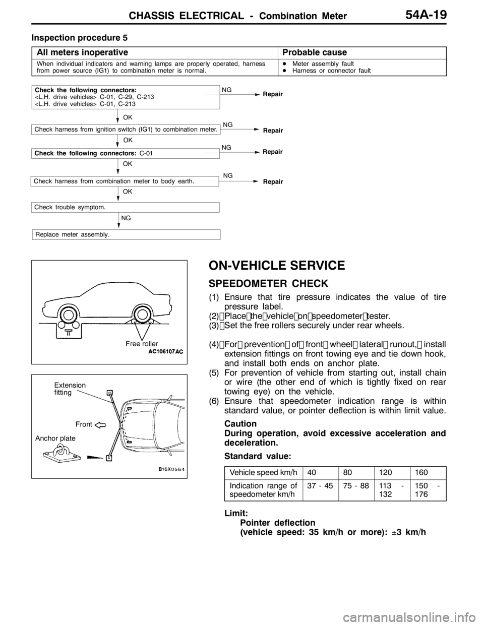
SPEEDOMETER CHECK
(1) Ensure that tire pressure indicates the value of tirepressure label.
(2) Place the vehicle on speedometer teste r.
(3)
(4) For prevention of front wheel lateral runout, install
extension fittings on front towing eye and tie down hook,
and install both ends on anchor plate.
(5) For prevention of vehicle from starting out, install chain or wire (the other end of which is tightly fixed on rear
towing eye) on the vehicle.
(6) Ensure that speedometer indication range is within standard value, or pointer deflection is within limit value.
Caution
During operation, avoid excessive acceleration and
deceleration.
Standard value:
Vehicle speed km/h4080120160
Indication range of
speedometer km/h37 - 4575 - 8811 3 -
132150 -
176
Limit:
Pointer deflection
(vehicle speed: 35 km/h or more): ±3 km/h
Extension
fitting
Front
Anchor plate
OK
Set the free rollers securely under rear wheels.