Page 1016 of 1449
POWER PLANT MOUNT - General Information32-2
GENERAL INFORMATION
Inertia principal axes system is incorporated into
the engine mount system.Upper installation of roll mount reduces engine
rolling, and increase of insulator bore also reduces
idle vibration.
CONSTRUCTION DIAGRAM
Transmission mount Engine mount
Rear roll rod bracket
Front roll stopper
Front roll mount bracketRear roll mount bracket
Crossmember
Crossmember bar
CentermemberRear roll rod assembly
Page 1018 of 1449
POWER PLANT MOUNT - Engine Mounting32-4
ENGINE MOUNTING
REMOVAL AND INSTALLATION
Caution
*: Indicates parts which should be initially tightened, and then fully tightened after placing the
vehicle horizontally and loading the full weight of the engine on the vehicle body.
Pre-removal and Post-installation Operation
DUnder Cover Removal and Installation (Refer to
GROUP 51 - Front Bumper.)DRaise the engine and transmission assembly until
its weight is not applied to the insulator, and support
it securely.
98±10 N·m*
67±7 N·m*
1
2
12±2 N·m
3 44
Removal steps
1. Power steering pressure hose as-
sembly
2. Engine mounting connecting bolt3. Engine mounting bracket
"AA4. Engine mounting insulator
INSTALLATION SERVICE POINT
"AAENGINE MOUNTING INSULATOR INSTALLATION
Arrow marks on the engine mount insulator should face the
shown direction.
NOTE
Disregard F and R stamped as a shared part.
Engine sideEngine side
Engine mounting insulator
>
Page 1019 of 1449

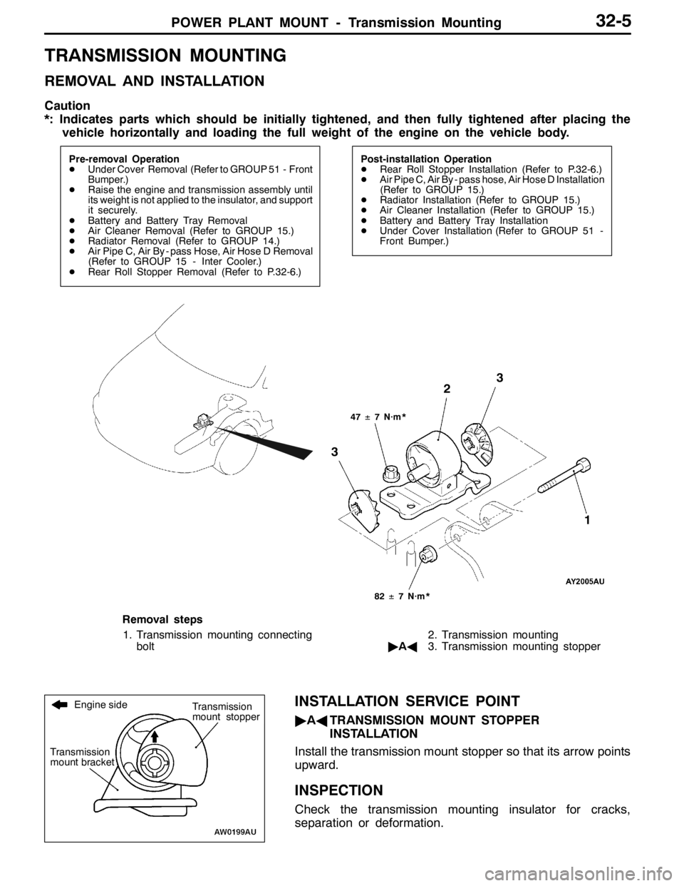
POWER PLANT MOUNT - Transmission Mounting32-5
TRANSMISSION MOUNTING
REMOVAL AND INSTALLATION
Caution
*: Indicates parts which should be initially tightened, and then fully tightened after placing the
vehicle horizontally and loading the full weight of the engine on the vehicle body.
Pre-removal Operation
DUnder Cover Removal (Refer to GROUP 51 - Front
Bumper.)
DRaise the engine and transmission assembly until
its weight is not applied to the insulator, and support
it securely.
DBattery and Battery Tray Removal
DAir Cleaner Removal (Refer to GROUP 15.)
DRadiator Removal (Refer to GROUP 14.)
DAir Pipe C, Air By - pass Hose, Air Hose D Removal
(Refer to GROUP 15 - Inter Cooler.)
DRear Roll Stopper Removal (Refer to P.32-6.)Post-installation Operation
DRear Roll Stopper Installation (Refer to P.32-6.)
DAir Pipe C, Air By - pass hose, Air Hose D Installation
(Refer to GROUP 15.)
DRadiator Installation (Refer to GROUP 15.)
DAir Cleaner Installation (Refer to GROUP 15.)
DBattery and Battery Tray Installation
DUnder Cover Installation (Refer to GROUP 51 -
Front Bumper.)
47±7 N·m*
3
3
82±7 N·m*
2
1
Removal steps
1. Transmission mounting connecting
bolt2. Transmission mounting
"AA3. Transmission mounting stopper
INSTALLATION SERVICE POINT
"AATRANSMISSION MOUNT STOPPER
INSTALLATION
Install the transmission mount stopper so that its arrow points
upward.
INSPECTION
Check the transmission mounting insulator for cracks,
separation or deformation.
Engine side
Transmission
mount bracketTransmission
mount stopper
Page 1025 of 1449

POWER PLANT MOUNT - Crossmember32-11
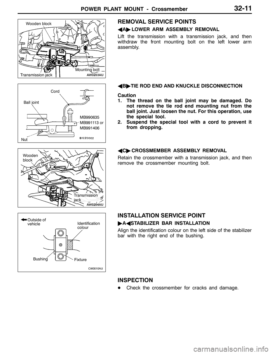
REMOVAL SERVICE POINTS
AA"LOWER ARM ASSEMBLY REMOVAL
Lift the transmission with a transmission jack, and then
withdraw the front mounting bolt on the left lower arm
assembly.
AB"TIE ROD END AND KNUCKLE DISCONNECTION
Caution
1. The thread on the ball joint may be damaged. Do
not remove the tie rod end mounting nut from the
ball joint.Just loosen the nut. For this operation, use
the special tool.
2. Suspend the special tool with a cord to prevent it
from dropping.
AC"CROSSMEMBER ASSEMBLY REMOVAL
Retain the crossmember with a transmission jack, and then
remove the crossmember mounting bolt.
INSTALLATION SERVICE POINT
"AASTABILIZER BAR INSTALLATION
Align the identification colour on the left side of the stabilizer
bar with the right end of the bushing.
INSPECTION
DCheck the crossmember for cracks and damage.
Wooden block
Transmission jack
Mounting bolt
Cord
Ball joint
MB990635
MB991113 or
MB991406
Nut
Wooden
block
Transmission
jack
Identification
colourOutside of
vehicle
BushingFixture
Page 1036 of 1449

FRONT SUSPENSION -Lower Arm Assembly33A-10
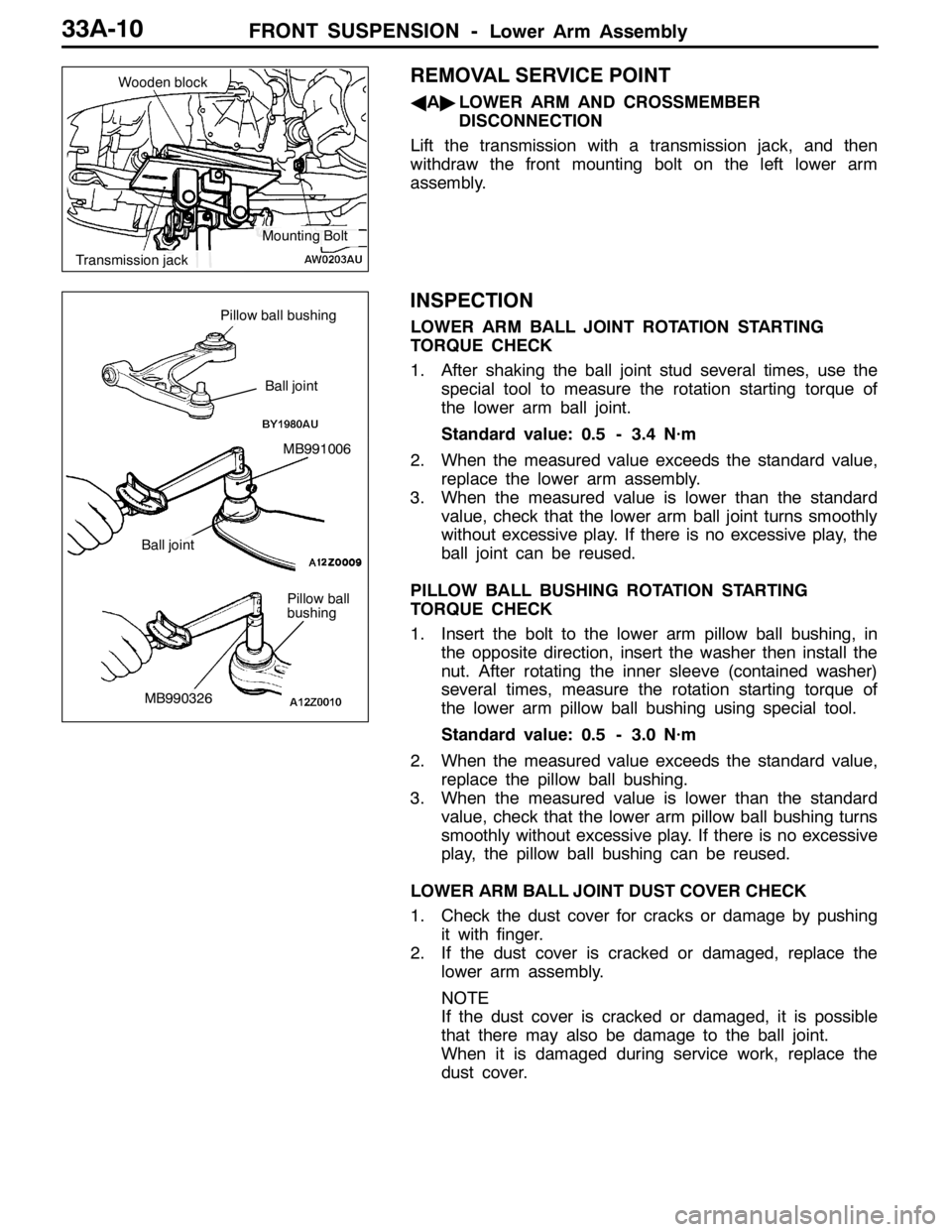
REMOVAL SERVICE POINT
AA"LOWER ARM AND CROSSMEMBER
DISCONNECTION
Lift the transmission with a transmission jack, and then
withdraw the front mounting bolt on the left lower arm
assembly.
INSPECTION
LOWER ARM BALL JOINT ROTATION STARTING
TORQUE CHECK
1. After shaking the ball joint stud several times, use the
special tool to measure the rotation starting torque of
the lower arm ball joint.
Standard value: 0.5 - 3.4 N·m
2. When the measured value exceeds the standard value,
replace the lower arm assembly.
3. When the measured value is lower than the standard
value, check that the lower arm ball joint turns smoothly
without excessive play. If there is no excessive play, the
ball joint can be reused.
PILLOW BALL BUSHING ROTATION STARTING
TORQUE CHECK
1. Insert the bolt to the lower arm pillow ball bushing, in
the opposite direction, insert the washer then install the
nut. After rotating the inner sleeve (contained washer)
several times, measure the rotation starting torque of
the lower arm pillow ball bushing using special tool.
Standard value: 0.5 - 3.0 N·m
2. When the measured value exceeds the standard value,
replace the pillow ball bushing.
3. When the measured value is lower than the standard
value, check that the lower arm pillow ball bushing turns
smoothly without excessive play. If there is no excessive
play, the pillow ball bushing can be reused.
LOWER ARM BALL JOINT DUST COVER CHECK
1. Check the dust cover for cracks or damage by pushing
it with finger.
2. If the dust cover is cracked or damaged, replace the
lower arm assembly.
NOTE
If the dust cover is cracked or damaged, it is possible
that there may also be damage to the ball joint.
When it is damaged during service work, replace the
dust cover.
Wooden block
Transmission jack
Mounting Bolt
Pillow ball
bushing
MB991006
Pillow ball bushing
Ball joint
Ball joint
MB990326
Page 1040 of 1449

FRONT SUSPENSION -Stabilizer Bar33A-14
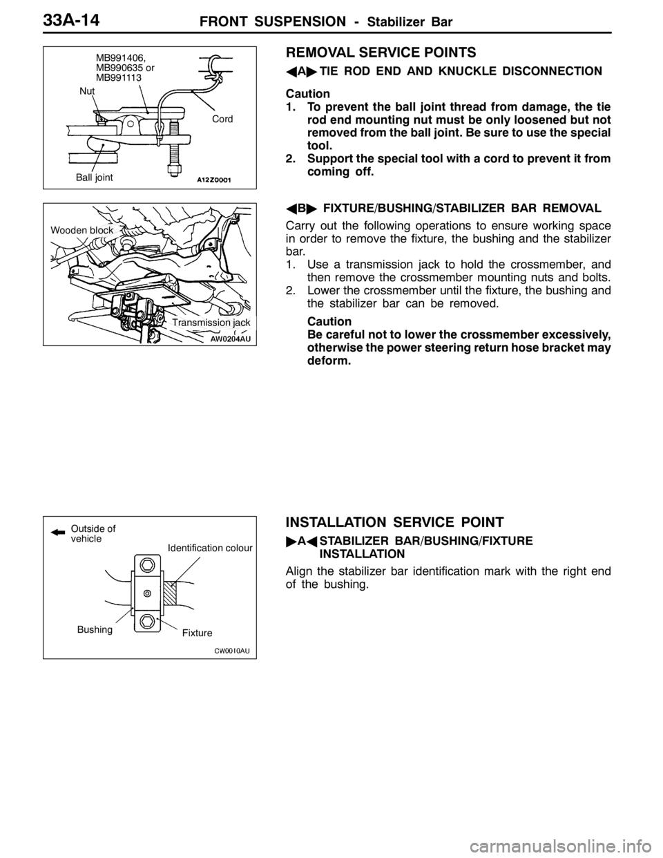
REMOVAL SERVICE POINTS
AA"TIE ROD END AND KNUCKLE DISCONNECTION
Caution
1. To prevent the ball joint thread from damage, the tie
rod end mounting nut must be only loosened but not
removed from the ball joint. Be sure to use the special
tool.
2. Support the special tool with a cord to prevent it from
coming off.
AB"FIXTURE/BUSHING/STABILIZER BAR REMOVAL
Carry out the following operations to ensure working space
in order to remove the fixture, the bushing and the stabilizer
bar.
1. Use a transmission jack to hold the crossmember, and
then remove the crossmember mounting nuts and bolts.
2. Lower the crossmember until the fixture, the bushing and
the stabilizer bar can be removed.
Caution
Be careful not to lower the crossmember excessively,
otherwise the power steering return hose bracket may
deform.
INSTALLATION SERVICE POINT
"AASTABILIZER BAR/BUSHING/FIXTURE
INSTALLATION
Align the stabilizer bar identification mark with the right end
of the bushing.
Cord
Ball jointNut
MB991406,
MB990635 or
MB991113
Transmission jack
Woodenblock
Identification colour
BushingFixture
Outside of
vehicle
Page 1116 of 1449

STEERING -General Information37A-2
GENERAL INFORMATION
The system has been equipped with the MOMO
leather 3-spoke-type steering wheel with built-in
SRS airbag.
The steering column is equipped with tilt steering
mechanism.
The power steering is an integral rack and piniontype that combines the steering gear and linkage
into one light-weight and compact assembly.
The steering system uses a vane oil pump with
a fluid flow control system, so that steering effort
varies with engine speed.
ItemLancer EVOLUTION-
Steering wheelTypeMOMO 3-spoke typeg
Outside diameter mm380 ,
365
Maximum number of turns2.1
Steering columnColumn mechanismTilt steering
Power steering typeIntegral type
Oil pumpTypeVariable capacity type (vane pump)pp
Basic discharge amount cm3/rev.9.6
Relief pressure MPa8.3 - 9.0
Reservoir typeSeparate type
Pressure switchEquipped
Steering gear and linkageTypeRack and pinionggg
Stroke ratio (Rack stroke/Steering wheel
Maximum turning radius)68.61
Rack stroke mm146
Steering angleInner wheel32°gg
Outer wheel (for reference)27°
Power steering fluidSpecified lubricantsAutomatic transmission fluid DEXRON IIg
Quantity LApproximately 1.0
Page 1118 of 1449

STEERING -Service Specifications/Lubricants/Sealant/Special Tools37A-4
SERVICE SPECIFICATIONS
ItemsStandard valueLimit
Steering wheel free play mmwhen engine running-30 or less
with engine stopped0-10-
Steering angleInner wheel31_45’±1_30’-
Outer wheel 27_15’-
Ball joint turning torque N·m1.0 - 3.0-
Stationary steering effort NSteering effort32 or less-
Fluctuation allowance6.0 or less-
Oil pump relief pressure MPa8.4 - 9.0-
Pressure under no-load conditions MPa0.2 - 0.8-
Steering gear retention hydraulic pressure MPa8.4 - 9.0-
Oil pressure switch operating
pressureMPa
OFF→ON1.8 - 2.4-
pressure MPaON→OFF1.0 - 2.4-
Total pinion torque N·mTotal rotation torque0.8 - 1.8-
Torque variation0.49 or less-
Tie rod joint swing resistance N (Tie rod joint swing torque N·m)8 - 27 (1.5 - 4.9)-
Opening dimension of special tool (MB991561) mm2.9-
Band crimped width mm2.4 - 2.8-
LUBRICANTS
ItemsSpecified lubricantQuantity
Power steering fluidAutomatic transmission fluid DEXRONIIApprox. 1.0 L
Tie rod bellowsSilicone greaseAs required
Pinion and valve assemblyRepair kit greaseAs required
Rack assembly
SEALANT
ItemsSpecified sealantRemarks
Toe boad (steering shaft cover
mounting bolt hole)3M ATD Part No. 8513 or equivalentDrying sealant
Rack support cover end plug3M ATD Part No. 8661, 8663 or equivalentSemi-drying sealant
SPECIAL TOOLS
ToolNumberNameUse
MB990635,
MB991113 or
MB991406Steering linkage
pullerDisconnection of tie rod end