Page 146 of 1575
6.The MICRO 570 will detect the amount of ripple from the charging system to the battery. Excessive ripple usually
means the stator is damaged or that one or more generator diodes have failed.
7.The MICRO 570 will prompt you to turn on accessary loads. It will then test at idle and prompt you to rev the
engine. The analyzer will determine if the charging system can provide enough current for the demands of the
vehicle's electrical system.
When asked to turn of the accessory loads, turn of the blower to high(heater), the high beam beadlights, and
rear defogger. DO NOT use cyclical loads such as air conditioning or wind- shield wipers.
8. After the test, the MICRO 570 will display the idle voltage, load voltage and the state results.
Page 1016 of 1575
a.Make sure the connector is plugged in properly.
b. Make sure the tailgate opens properly and locks securely.
REAR WIPER REPLACEMENT
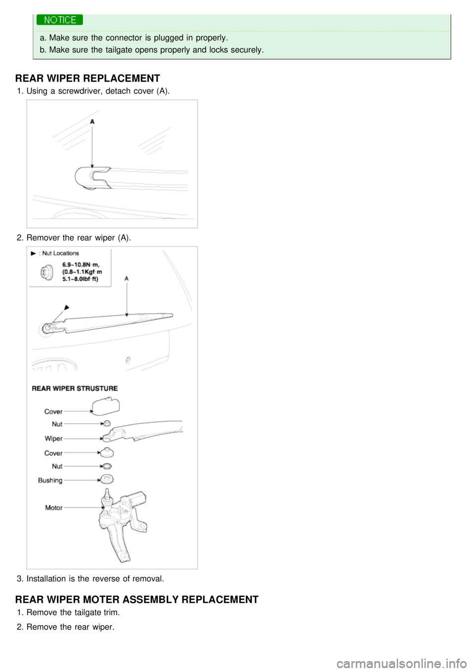
1.Using a screwdriver, detach cover (A).
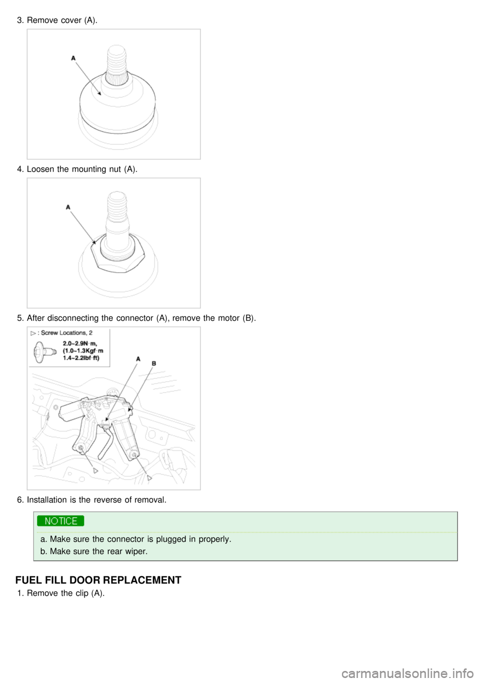
2.Remover the rear wiper (A).
3.Installation is the reverse of removal.
REAR WIPER MOTER ASSEMBLY REPLACEMENT
1.Remove the tailgate trim.
2. Remove the rear wiper.
Page 1017 of 1575
3.Remove cover (A).
4.Loosen the mounting nut (A).
5.After disconnecting the connector (A), remove the motor (B).
6.Installation is the reverse of removal.
a.Make sure the connector is plugged in properly.
b. Make sure the rear wiper.
FUEL FILL DOOR REPLACEMENT
1.Remove the clip (A).
Page 1211 of 1575
2007 > 2.7L V6 GASOLINE >
DESCRIPTION
All modules are linked a low speed CAN network.
The input information for the modules is coming from both the CAN network and the hardware components
(actuatorsand sensors).
a. FAM (Front Area Module)
a. Headlamp low/high beam control (with DRL)
b. Park lamp control
c. Front fog lamp control
d. Front turn signal lamp control
e. Windshield wiper control
f. Windshield deicer
g. Diagnostics
b. IPM (In - Panel Module)
a. RKE (Remote Keyless Control)
b. VAS (Voice Alarm System)
c. Ignition key hole illumination
d. Switch indicators control
e. Panel light control
f. Seat belt warning
g. Auto light/DRL control (Logic)
h. Windshield/Rear wiper control (Logic)
i. Turn and Hazard lamp control (Logic)
j. Central door lock (Logic)
k. Windshield deicer timer
l. Rear glass defog timer
m. Gateway for ISO- 9141 (K- Line)
c. RAM (Rear Area Module)
a. Tail lamp control
b. Turn and Hazard lamp control
c. Back up lamp control
d. Rea fog lamp control
e. Stop lamp outage detection
f. Sliding door power window/Quarter glass control
g. Room lamp control
h. Rear wiper control
i. Rear glass defog
j. Fuel filler door open solenoid control
d. ADM (Assist Drive Module)
e. DDM (Driver Drive Module)
MODULE INTRODUCTION
FAM/IPM/RAM consists of a power board and an electronic board. The power board contains circuit protection devices
and switching devices. The electronic board uses Intelligent Power Switching (IPS) for HS/LS load control, logic
functions and CAN/K- Line communication. The power board and electronic board are connected with pin blocks for
the Front Area Module (FAM) and VCD (Variable Connection Displacement) for the In- Panel Module (IPM) and the
Rear Area Module (RAM).
Page 1222 of 1575
Dimmable Backlighting
1.Working Conditions
The Dimmable backlighting is directly managed by the rheostat.
Power Seat Switch Illumination
1.Working Conditions
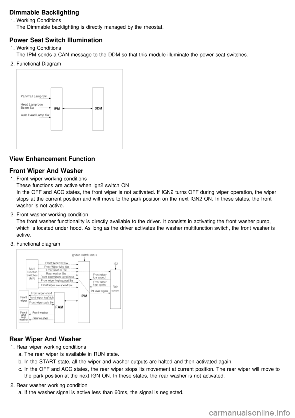
The IPM sends a CAN message to the DDM so that this module illuminate the power seat switches.
2. Functional Diagram
View Enhancement Function
Front Wiper And Washer
1.Front wiper working conditions
These functions are active when Ign2 switch ON
In the OFF and ACC states, the front wiper is not activated. If IGN2 turns OFF during wiper operation, the wiper
stops at the current position and will move to the park position on the next IGN2 ON. In these states, the front
washer is not active.
2. Front washer working condition
The front washer functionality is directly available to the driver. It consists in activating the front washer pump,
which is located under hood. As long as the driver activates the washer multifunction switch, the front washer is
active.
3. Functional diagram
Rear Wiper And Washer
1.Rear wiper working conditions
a. The rear wiper is available in RUN state.
b. In the START state, all the wiper and washer outputs are halted and then activated again.
c. In the OFF and ACC states, the rear wiper stops its movement at current position. The rear wiper will move to
the park position at the next IGN ON. In these states, the rear washer is not activated.
2. Rear washer working condition
a. If the washer signal is active less than 60ms, the signal is neglected.
Page 1223 of 1575
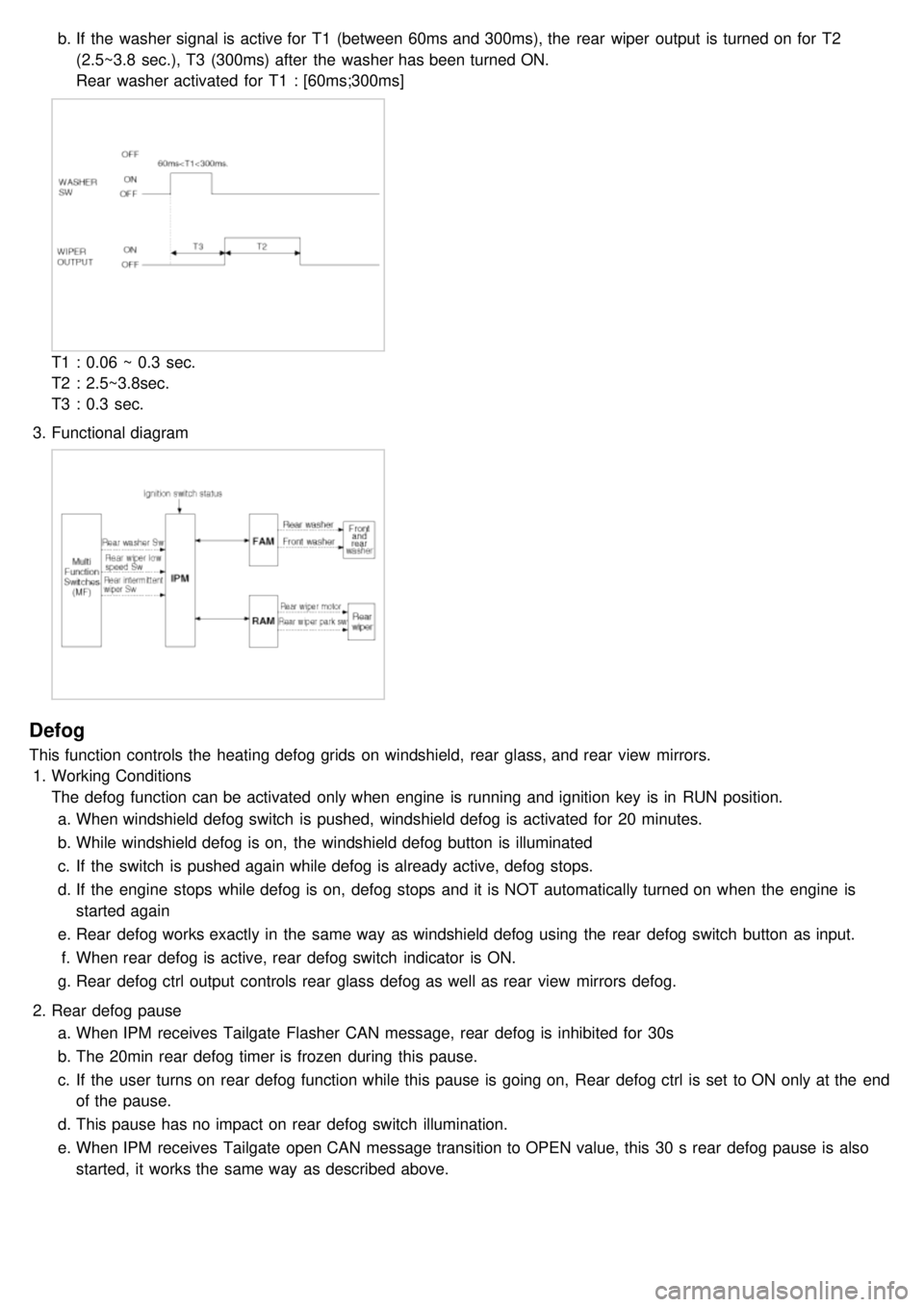
b.If the washer signal is active for T1 (between 60ms and 300ms), the rear wiper output is turned on for T2
(2.5~3.8 sec.), T3 (300ms) after the washer has been turned ON.
Rear washer activated for T1 : [60ms;300ms]
T1 : 0.06 ~ 0.3 sec.
T2 : 2.5~3.8sec.
T3 : 0.3 sec.
3. Functional diagram
Defog
This function controls the heating defog grids on windshield, rear glass, and rear view mirrors.
1. Working Conditions
The defog function can be activated only when engine is running and ignition key is in RUN position.
a. When windshield defog switch is pushed, windshield defog is activated for 20 minutes.
b. While windshield defog is on, the windshield defog button is illuminated
c. If the switch is pushed again while defog is already active, defog stops.
d. If the engine stops while defog is on, defog stops and it is NOT automatically turned on when the engine is
started again
e. Rear defog works exactly in the same way as windshield defog using the rear defog switch button as input.
f. When rear defog is active, rear defog switch indicator is ON.
g. Rear defog ctrl output controls rear glass defog as well as rear view mirrors defog.
2. Rear defog pause
a. When IPM receives Tailgate Flasher CAN message, rear defog is inhibited for 30s
b. The 20min rear defog timer is frozen during this pause.
c. If the user turns on rear defog function while this pause is going on, Rear defog ctrl is set to ON only at the end
of the pause.
d. This pause has no impact on rear defog switch illumination.
e. When IPM receives Tailgate open CAN message transition to OPEN value, this 30 s rear defog pause is also
started, it works the same way as described above.
Page 1241 of 1575
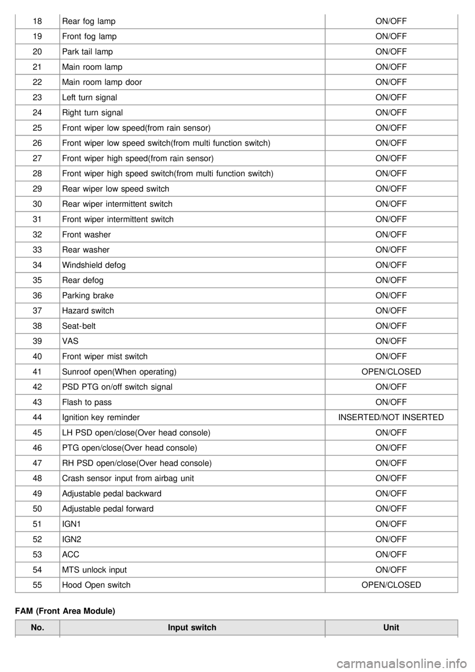
18Rear fog lamp ON/OFF
19 Front fog lamp ON/OFF
20 Park tail lamp ON/OFF
21 Main room lamp ON/OFF
22 Main room lamp door ON/OFF
23 Left turn signal ON/OFF
24 Right turn signal ON/OFF
25 Front wiper low speed(from rain sensor) ON/OFF
26 Front wiper low speed switch(from multi function switch) ON/OFF
27 Front wiper high speed(from rain sensor) ON/OFF
28 Front wiper high speed switch(from multi function switch) ON/OFF
29 Rear wiper low speed switch ON/OFF
30 Rear wiper intermittent switch ON/OFF
31 Front wiper intermittent switch ON/OFF
32 Front washer ON/OFF
33 Rear washer ON/OFF
34 Windshield defog ON/OFF
35 Rear defog ON/OFF
36 Parking brake ON/OFF
37 Hazard switch ON/OFF
38 Seat- belt ON/OFF
39 VAS ON/OFF
40 Front wiper mist switch ON/OFF
41 Sunroof open(When operating) OPEN/CLOSED
42 PSD PTG on/off switch signal ON/OFF
43 Flash to pass ON/OFF
44 Ignition key reminder INSERTED/NOT INSERTED
45 LH PSD open/close(Over head console) ON/OFF
46 PTG open/close(Over head console) ON/OFF
47 RH PSD open/close(Over head console) ON/OFF
48 Crash sensor input from airbag unit ON/OFF
49 Adjustable pedal backward ON/OFF
50 Adjustable pedal forward ON/OFF
51 IGN1 ON/OFF
52 IGN2 ON/OFF
53 ACC ON/OFF
54 MTS unlock input ON/OFF
55 Hood Open switch OPEN/CLOSED
FAM (Front Area Module) No. Input switch Unit
Page 1242 of 1575
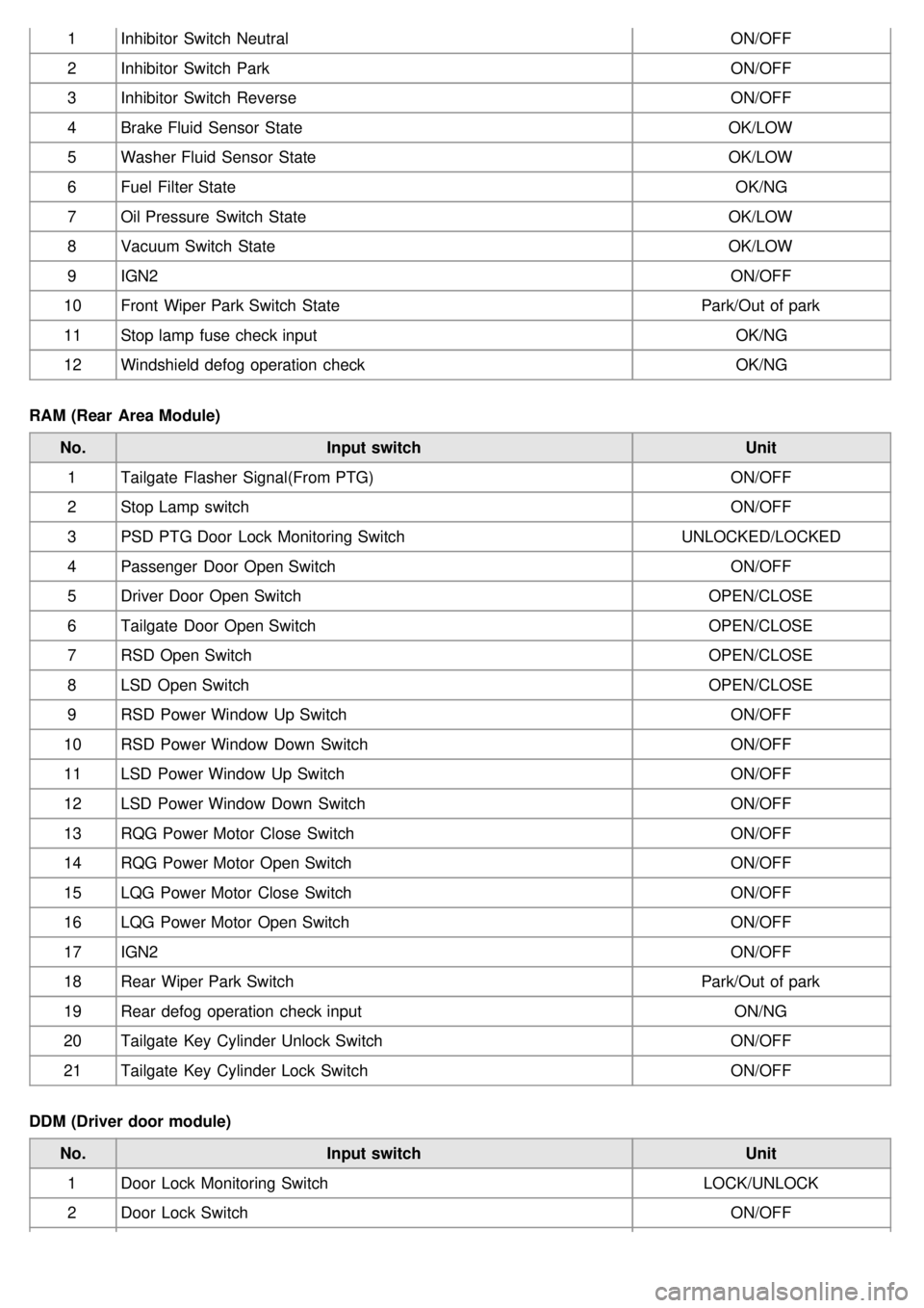
1Inhibitor Switch Neutral ON/OFF
2 Inhibitor Switch Park ON/OFF
3 Inhibitor Switch Reverse ON/OFF
4 Brake Fluid Sensor State OK/LOW
5 Washer Fluid Sensor State OK/LOW
6 Fuel Filter State OK/NG
7 Oil Pressure Switch State OK/LOW
8 Vacuum Switch State OK/LOW
9 IGN2 ON/OFF
10 Front Wiper Park Switch State Park/Out of park
11 Stop lamp fuse check input OK/NG
12 Windshield defog operation check OK/NG
RAM (Rear Area Module) No. Input switch Unit
1 Tailgate Flasher Signal(From PTG) ON/OFF
2 Stop Lamp switch ON/OFF
3 PSD PTG Door Lock Monitoring Switch UNLOCKED/LOCKED
4 Passenger Door Open Switch ON/OFF
5 Driver Door Open Switch OPEN/CLOSE
6 Tailgate Door Open Switch OPEN/CLOSE
7 RSD Open Switch OPEN/CLOSE
8 LSD Open Switch OPEN/CLOSE
9 RSD Power Window Up Switch ON/OFF
10 RSD Power Window Down Switch ON/OFF
11 LSD Power Window Up Switch ON/OFF
12 LSD Power Window Down Switch ON/OFF
13 RQG Power Motor Close Switch ON/OFF
14 RQG Power Motor Open Switch ON/OFF
15 LQG Power Motor Close Switch ON/OFF
16 LQG Power Motor Open Switch ON/OFF
17 IGN2 ON/OFF
18 Rear Wiper Park Switch Park/Out of park
19 Rear defog operation check input ON/NG
20 Tailgate Key Cylinder Unlock Switch ON/OFF
21 Tailgate Key Cylinder Lock Switch ON/OFF
DDM (Driver door module) No. Input switch Unit
1 Door Lock Monitoring Switch LOCK/UNLOCK
2 Door Lock Switch ON/OFF