2007 KIA CARNIVAL key
[x] Cancel search: keyPage 1333 of 1575
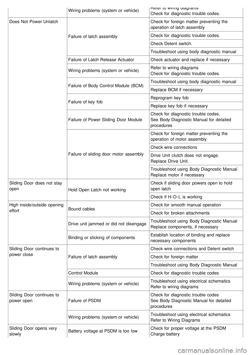
Wiring problems (system or vehicle)Refer to wiring diagrams
Check for diagnostic trouble codes.
Does Not Power Unlatch
Failure of latch assembly Check for foreign matter preventing the
operation of latch assembly
Check for diagnostic trouble codes.
Check Detent switch.
Troubleshoot using body diagnostic manual
Failure of Latch Release Actuator Check actuator and replace if necessary
Wiring problems (system or vehicle) Refer to wiring diagrams
Check for diagnostic trouble codes.
Failure of Body Control Module (BCM) Troubleshoot using body diagnostic manual
Replace BCM if necessary
Failure of key fob Reprogram key fob
Replace key fob if necessary
Failure of Power Sliding Door Module Check for diagnostic trouble codes.
See Body Diagnostic Manual for detailed
procedures
Failure of sliding door motor assembly Check for foreign matter preventing the
operation of motor assembly
Check wire connections
Drive Unit clutch does not engage.
Replace Drive Unit.
Troubleshoot using Body Diagnostic Manual
Replace motor if necessary
Sliding Door does not stay
open Hold Open Latch not working Check if sliding door powers open to hold
open latch
Check if H- O - L is working
High inside/outside opening
effort Bound cables Check for smooth manual operation
Check for broken attachments
Drive unit jammed or did not disengage Troubleshoot using Body Diagnostic Manual
Replace components, if necessary
Binding or sticking of components Establish location of binding and replace
necessary components
Sliding Door continues to
power close Failure of latch assembly Check wire connections and Detent switch
Check for foreign matter
Troubleshoot using Body Diagnostic Manual
Control Module Check for diagnostic trouble codes
Wiring problems (system or vehicle) Troubleshoot using electrical schematics
Refer to wiring diagrams
Sliding Door continues to
power open Failure of PSDM Check for diagnostic trouble codes
See Body Diagnostic Manual for detailed
procedures
Wiring problems (system or vehicle) Troubleshoot using electrical schematics
Refer to Wiring Diagrams
Sliding Door opens very
slowly Battery voltage at PSDM is too low
Check for proper voltage at the PSDM
Charge battery
Page 1367 of 1575
2007 > 2.7L V6 GASOLINE >
DESCRIPTION
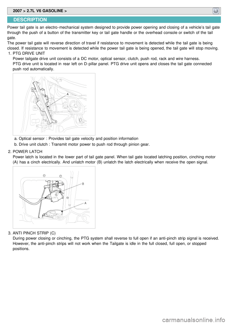
Power tail gate is an electro - mechanical system designed to provide power opening and closing of a vehicle’s tail gate
through the push of a button of the transmitter key or tail gate handle or the overhead console or switch of the tail
gate.
The power tail gate will reverse direction of travel if resistance to movement is detected while the tail gate is being
closed. If resistance to movement is detected while the power tail gate is being opened, the tail gate will stop moving.
1. PTG DRIVE UNIT
Power tailgate drive unit consists of a DC motor, optical sensor, clutch, push rod, rack and wire harness.
PTG drive unit is located in rear left on D- pillar panel. PTG drive unit opens and closes the tail gate connected
push rod automatically.
a.Optical sensor : Provides tail gate velocity and position information
b. Drive unit clutch : Transmit motor power to push rod through pinion gear.
2. POWER LATCH
Power latch is located in the lower part of tail gate panel. When tail gate located latching position, cinching motor
(A) has a cinch electrically. And unlatch motor (B) unlatch the latch electrically when receive the open signal.
3.ANTI PINCH STRIP (C)
During power closing or cinching, the PTG system shall reverse to full open if an anti- pinch strip signal is received.
However, the anti- pinch strips will not work when the Tailgate is idle in the full closed, full open, or stopped
positions.
Page 1368 of 1575
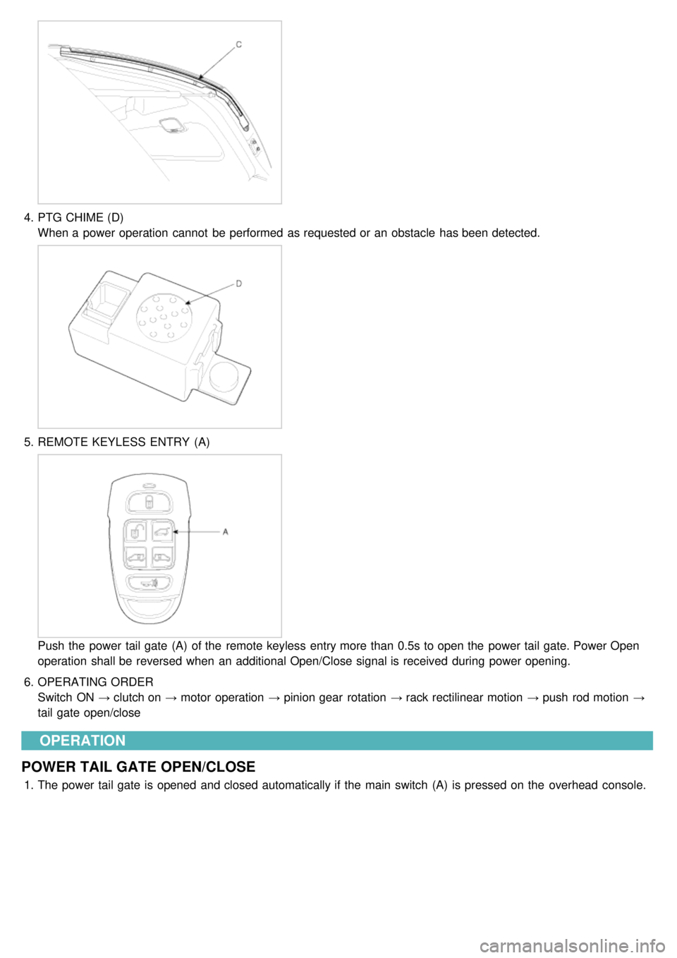
4.PTG CHIME (D)
When a power operation cannot be performed as requested or an obstacle has been detected.
5.REMOTE KEYLESS ENTRY (A)
Push the power tail gate (A) of the remote keyless entry more than 0.5s to open the power tail gate. Power Open
operation shall be reversed when an additional Open/Close signal is received during power opening.
6. OPERATING ORDER
Switch ON → clutch on → motor operation → pinion gear rotation → rack rectilinear motion → push rod motion →
tail gate open/close
OPERATION
POWER TAIL GATE OPEN/CLOSE
1. The power tail gate is opened and closed automatically if the main switch (A) is pressed on the overhead console.
Page 1373 of 1575
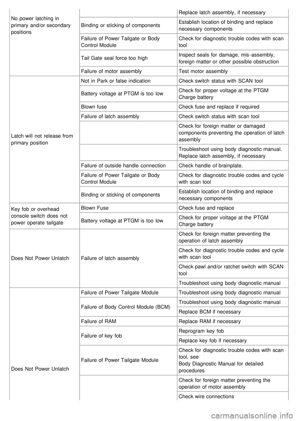
No power latching in
primary and/or secondary
positionsReplace latch assembly, if necessary
Binding or sticking of components Establish location of binding and replace
necessary components
Failure of Power Tailgate or Body
Control Module Check for diagnostic trouble codes with scan
tool
Tail Gate seal force too high Inspect seals for damage, mis - assembly,
foreign matter or other possible obstruction
Failure of motor assembly Test motor assembly
Latch will not release from
primary position Not in Park or false indication
Check switch status with SCAN tool
Battery voltage at PTGM is too low Check for proper voltage at the PTGM
Charge battery
Blown fuse Check fuse and replace if required
Failure of latch assembly Check switch status with scan tool
Check for foreign matter or damaged
components preventing the operation of latch
assembly
Troubleshoot using body diagnostic manual.
Replace latch assembly, if necessary
Failure of outside handle connection Check handle of brainplate.
Failure of Power Tailgate or Body
Control Module Check for diagnostic trouble codes and cycle
with scan tool
Binding or sticking of components Establish location of binding and replace
necessary components
Key fob or overhead
console switch does not
power operate tailgate Blown Fuse
Check fuse and replace
Battery voltage at PTGM is too low Check for proper voltage at the PTGM
Charge battery
Does Not Power Unlatch Failure of latch assembly Check for foreign matter preventing the
operation of latch assembly
Check for diagnostic trouble codes and cycle
with scan tool
Check pawl and/or ratchet switch with SCAN
tool
Troubleshoot using body diagnostic manual
Does Not Power Unlatch Failure of Power Tailgate Module
Troubleshoot using body diagnostic manual
Failure of Body Control Module (BCM) Troubleshoot using body diagnostic manual
Replace BCM if necessary
Failure of RAM Replace RAM if necessary
Failure of key fob Reprogram key fob
Replace key fob if necessary
Failure of Power Tailgate Module Check for diagnostic trouble codes with scan
tool, see
Body Diagnostic Manual for detailed
procedures
Check for foreign matter preventing the
operation of motor assembly
Check wire connections
Page 1387 of 1575
2007 > 2.7L V6 GASOLINE >
INPECTION
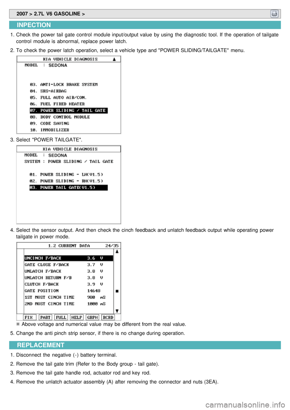
1.Check the power tail gate control module input/output value by using the diagnostic tool. If the operation of tailgate
control module is abnormal, replace power latch.
2. To check the power latch operation, select a vehicle type and "POWER SLIDING/TAILGATE" menu.
3.Select "POWER TAILGATE".
4.Select the sensor output. And then check the cinch feedback and unlatch feedback output while operating power
tailgate in power mode.
※ Above voltage and numerical value may be different from the real value.
5. Change the anti pinch strip sensor, if there is no change during operation.
REPLACEMENT
1.Disconnect the negative ( - ) battery terminal.
2. Remove the tail gate trim (Refer to the Body group - tail gate).
3. Remove the tail gate handle rod, actuator rod and key rod.
4. Remove the unlatch actuator assembly (A) after removing the connector and nuts (3EA).
Page 1420 of 1575
2007 > 2.7L V6 GASOLINE >
INSPECTION
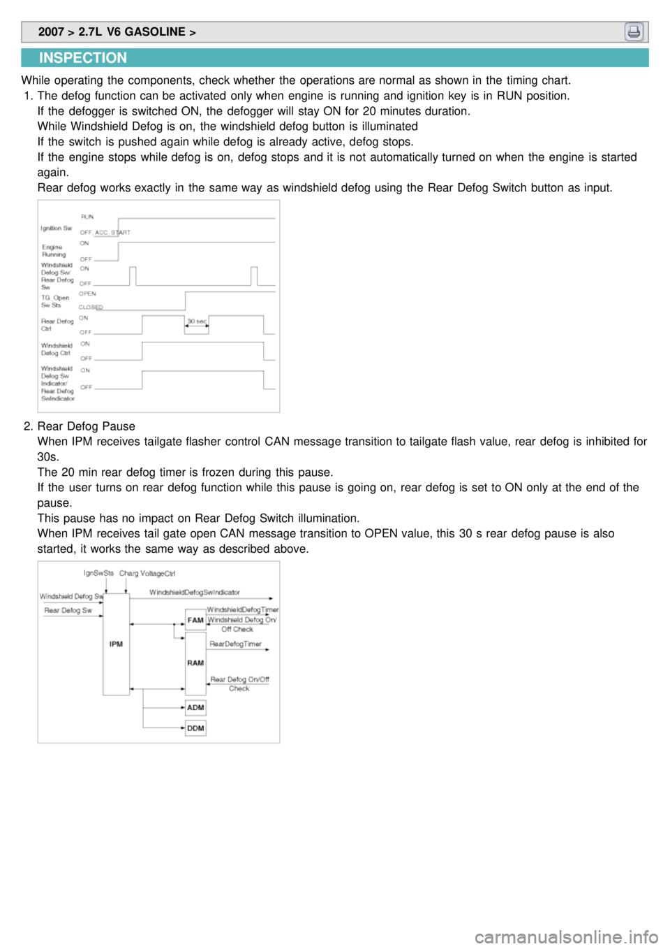
While operating the components, check whether the operations are normal as shown in the timing chart.
1. The defog function can be activated only when engine is running and ignition key is in RUN position.
If the defogger is switched ON, the defogger will stay ON for 20 minutes duration.
While Windshield Defog is on, the windshield defog button is illuminated
If the switch is pushed again while defog is already active, defog stops.
If the engine stops while defog is on, defog stops and it is not automatically turned on when the engine is started
again.
Rear defog works exactly in the same way as windshield defog using the Rear Defog Switch button as input.
2.Rear Defog Pause
When IPM receives tailgate flasher control CAN message transition to tailgate flash value, rear defog is inhibited for
30s.
The 20 min rear defog timer is frozen during this pause.
If the user turns on rear defog function while this pause is going on, rear defog is set to ON only at the end of the
pause.
This pause has no impact on Rear Defog Switch illumination.
When IPM receives tail gate open CAN message transition to OPEN value, this 30 s rear defog pause is also
started, it works the same way as described above.
Page 1434 of 1575
2007 > 2.7L V6 GASOLINE >
DESCRIPTION
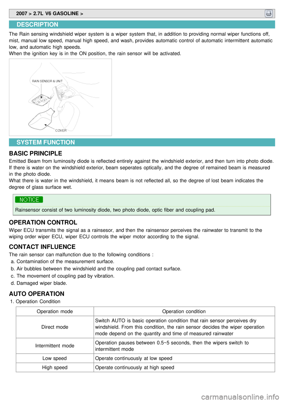
The Rain sensing windshield wiper system is a wiper system that, in addition to providing normal wiper functions off,
mist, manual low speed, manual high speed, and wash, provides automatic control of automatic intermittent automatic
low, and automatic high speeds.
When the ignition key is in the ON position, the rain sensor will be activated.
SYSTEM FUNCTION
BASIC PRINCIPLE
Emitted Beam from luminosity diode is reflected entirely against the windshield exterior, and then turn into photo diode.
If there is water on the windshield exterior, beam seperates optically, and the degree of remained beam is measured
in the photo diode.
What there is water in the windshield, it means beam is not reflected all, so the degree of lost beam indicates the
degree of glass surface wet.
Rainsensor consist of two luminosity diode, two photo diode, optic fiber and coupling pad.
OPERATION CONTROL
Wiper ECU transmits the signal as a rainsesor, and then the rainsensor perceives the rainwater to transmit to the
wiping order wiper ECU, wiper ECU controls the wiper motor according to the signal.
CONTACT INFLUENCE
The rain sensor can malfunction due to the following conditions : a. Contamination of the measurement surface.
b. Air bubbles between the windshield and the coupling pad contact surface.
c. The movement of coupling pad by vibration.
d. Damaged wiper blade.
AUTO OPERATION
1.Operation Condition
Operation mode Operation condition
Direct mode Switch AUTO is basic operation condition that rain sensor perceives dry
windshield. From this condition, the rain sensor decides the wiper operation
mode depend on the quantity and time of measured rainwater
Intermittent mode Operation pauses between 0.5~5 seconds, then the wipers switch to
intermittent mode
Low speed Operate continuously at low speed
High speed Operate continuously at high speed
Page 1448 of 1575
2007 > 2.7L V6 GASOLINE >
INSPECTION
Check it by the procedure below to see if the function of the ECM is normal.
1. Turn the ignition key to the "ON" position.
2. Cover the front sensor to stop functioning.
3. Shine a light at the rear sensor.
4. The ECM should be darkened as soon as the rear sensor detects the light.
If this test is performed in daytime, the mirror may be darkened as soon as the looking sensor is covered.
5. When the reverse gear is engaged, the ECM should not be darkened.
REPLACEMENT
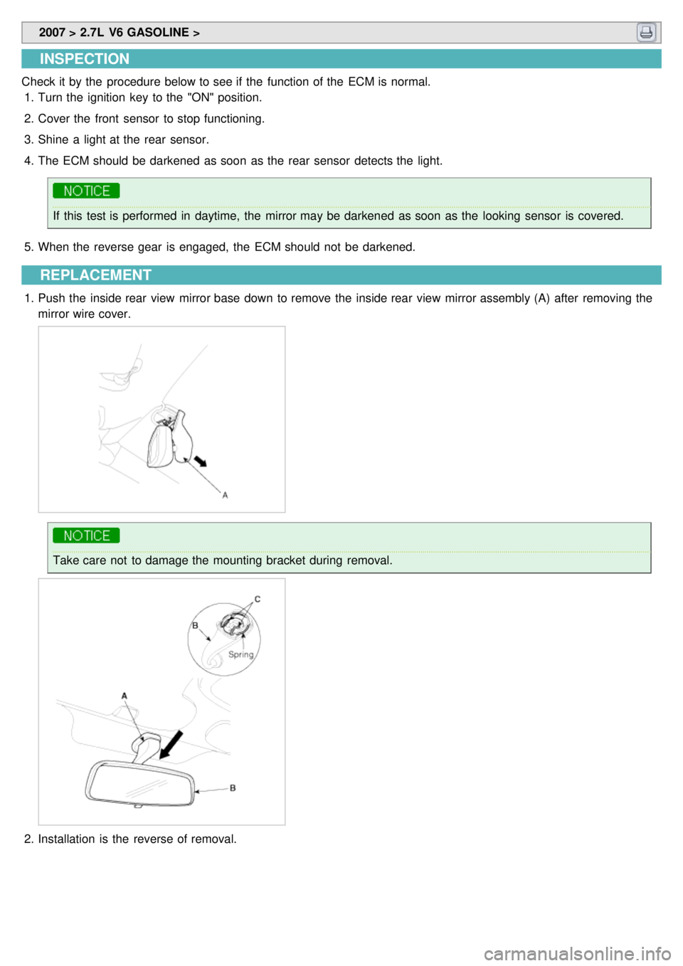
1.Push the inside rear view mirror base down to remove the inside rear view mirror assembly (A) after removing the
mirror wire cover.
Take care not to damage the mounting bracket during removal.
2.Installation is the reverse of removal.