2007 KIA CARNIVAL key
[x] Cancel search: keyPage 1259 of 1575
2007 > 2.7L V6 GASOLINE >
DESCRIPTION
An optimal seat position set by a driver can be memorized in P/seat unit by memory SW and position SW, which
enables restoration of seat position set by the driver despite seat adjustments.
Furthermore, data is transmitted between P/seat and IPM, DDM, ADM, RAM, FAM, CLUSTER through CAN BUS.
Seat position presets cannot be recalled while driving. An emergency stop function is provided; additional functions are
described below.
1. It conducts manual operation of seat by CAN BUS data transmitted by DDM as well as that of adjustable pedal by
CAN BUS data transmitted by IPM received when operating SW manually.
2. Manual SW behavior when communication stops (back- up behavior)
a. Slide front/rear
b. Recline front/rear
c. Position control of slide motor is possible by manual SW even in case of congestion in CPU or removal of a
fuse for P/seat unit B.
3. 2 memory locations are provided for storing seat, outside mirror, and adjustable pedal presets.
4. The driver seat can be set to slide rearward when the ignition key is removed, and forward when the key is
inserted.
5. 2 additional presets for seat, mirror, and adjustable pedal position can be stored with the RKE transmitter.
OPERATION
MANUAL OPERATION
Manual operation of the driver seat and adjustable pedals is possible provided the transaxle is in 'P' range and the
vehicle speed is 0 MPH. Operation of the manual controls overrides any automatic operation commanded via CAN.
MEMORY OPERATION
1. Pressing the 'M' button on the control panel will place the system into memory storage mode and will result in a
single pulse from the output buzzer.
2. If one of the memory location buttons is pressed and held within 5 seconds of pressing the 'M' button, the output
buzzer will pulse twice to indicate successful storage of seat, mirror, and adjustable pedal positions.
3. The ignition switch must be in the RUN or START position, the vehicle speed must be 0 MPH, and the transaxle
must be in 'P' range to store memory presets.
4. Pressing the 'M' button while recalling a stored preset will halt the preset recall operation.
5. Memory will be cleared if battery is removed.
MEMORY REPLAY OPERATION
1.Pressing one of the memory location buttons will result in the driver seat, outside mirrors, and adjustable pedals
being positioned based on the stored preset data.
2. The ignition switch must be in the RUN position, the transaxle must be in 'P' range, the vehicle speed must be 0
MPH, and the manual functions must not be in operation to recall stored presets.
3. Others
a. Play operation not recorded in the position switch will not be conducted and there will be no buzzer output.
b. If other data is received during preset recall operation, the most recent preset recall signal will take
precedence.
c. If engine is started during preset recall operation, halt preset recall operation, and resume it toward target
position 100ms after Ignition switch is returned to "RUN". However, if the START state lasts over 5 sec., it will
not resume even after returning to RUN.
d. If preset recall order is received during engine start, preset recall operation is inhibited.
e. If input from manual switch for seat and adjust pedal occurs during preset recall operation of seat and adjust
pedal, halt all their preset recall operations.
f. If an error occurs during manual operation of seat and adjust pedal, delete Memory.
Page 1260 of 1575
4.Operation control
a. Prioritization of operations
Motor starting is delayed for 100ms respectively in case of auto control to prevent rush current from overlap
when motors are running, and it follows the following order.
Slide > recline > front height > rear height > adjust pedal
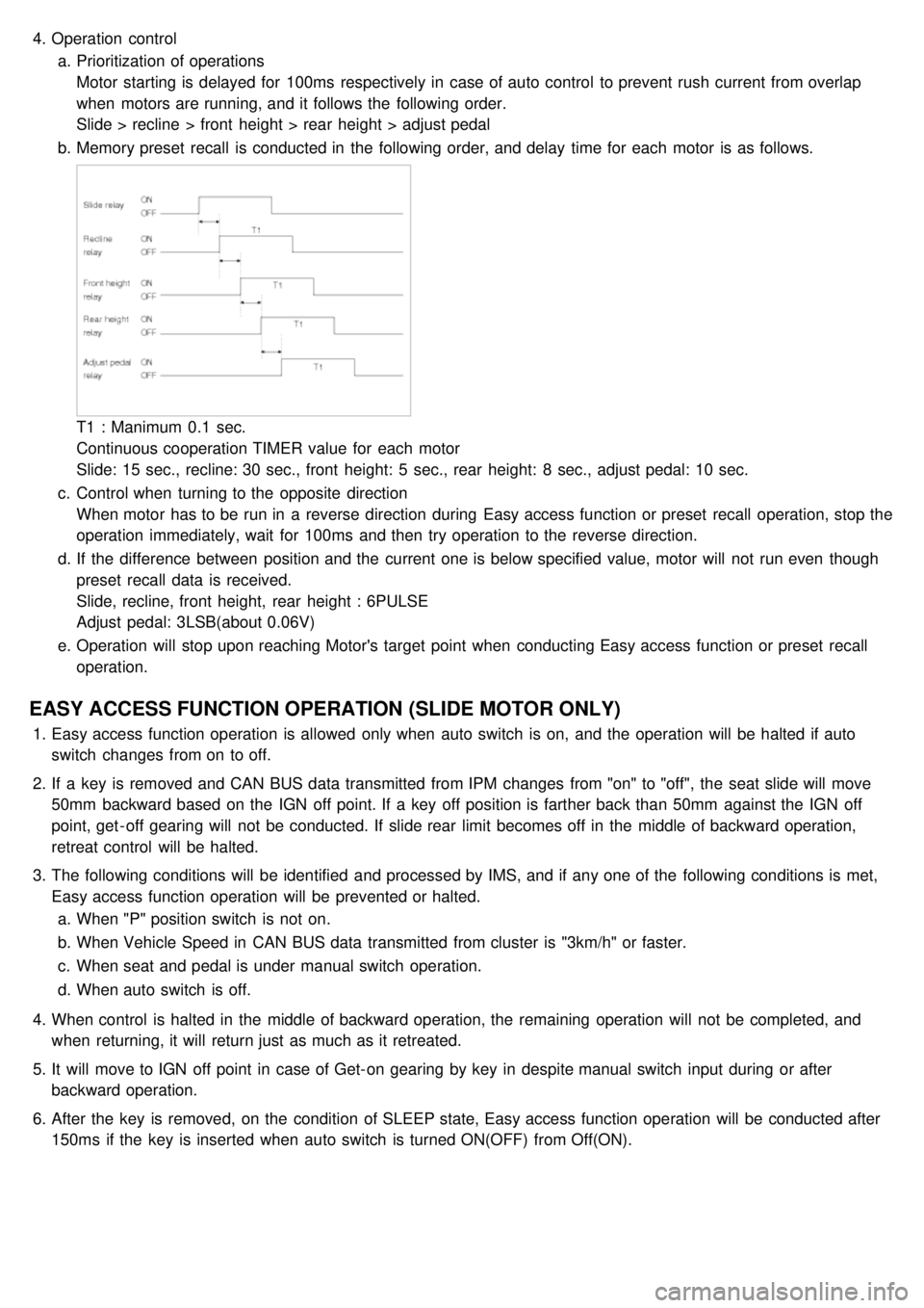
b. Memory preset recall is conducted in the following order, and delay time for each motor is as follows.
T1 : Manimum 0.1 sec.
Continuous cooperation TIMER value for each motor
Slide: 15 sec., recline: 30 sec., front height: 5 sec., rear height: 8 sec., adjust pedal: 10 sec.
c. Control when turning to the opposite direction
When motor has to be run in a reverse direction during Easy access function or preset recall operation, stop the
operation immediately, wait for 100ms and then try operation to the reverse direction.
d. If the difference between position and the current one is below specified value, motor will not run even though
preset recall data is received.
Slide, recline, front height, rear height : 6PULSE
Adjust pedal: 3LSB(about 0.06V)
e. Operation will stop upon reaching Motor's target point when conducting Easy access function or preset recall
operation.
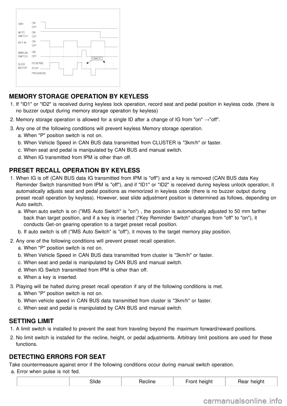
EASY ACCESS FUNCTION OPERATION (SLIDE MOTOR ONLY)
1.Easy access function operation is allowed only when auto switch is on, and the operation will be halted if auto
switch changes from on to off.
2. If a key is removed and CAN BUS data transmitted from IPM changes from "on" to "off", the seat slide will move
50mm backward based on the IGN off point. If a key off position is farther back than 50mm against the IGN off
point, get - off gearing will not be conducted. If slide rear limit becomes off in the middle of backward operation,
retreat control will be halted.
3. The following conditions will be identified and processed by IMS, and if any one of the following conditions is met,
Easy access function operation will be prevented or halted.
a. When "P" position switch is not on.
b. When Vehicle Speed in CAN BUS data transmitted from cluster is "3km/h" or faster.
c. When seat and pedal is under manual switch operation.
d. When auto switch is off.
4. When control is halted in the middle of backward operation, the remaining operation will not be completed, and
when returning, it will return just as much as it retreated.
5. It will move to IGN off point in case of Get- on gearing by key in despite manual switch input during or after
backward operation.
6. After the key is removed, on the condition of SLEEP state, Easy access function operation will be conducted after
150ms if the key is inserted when auto switch is turned ON(OFF) from Off(ON).
Page 1261 of 1575
MEMORY STORAGE OPERATION BY KEYLESS
1.If "ID1" or "ID2" is received during keyless lock operation, record seat and pedal position in keyless code. (there is
no buzzer output during memory storage operation by keyless)
2. Memory storage operation is allowed for a single ID after a change of IG from "on" →"off".
3. Any one of the following conditions will prevent keyless Memory storage operation.
a. When "P" position switch is not on.
b. When Vehicle Speed in CAN BUS data transmitted from CLUSTER is "3km/h" or faster.
c. When seat and pedal is manipulated by CAN BUS and manual switch.
d. When IG transmitted from IPM is other than off.
PRESET RECALL OPERATION BY KEYLESS
1.When IG is off (CAN BUS data IG transmitted from IPM is "off") and a key is removed (CAN BUS data Key
Reminder Switch transmitted from IPM is "off"), and if "ID1" or "ID2" is received during keyless unlock operation, it
automatically adjusts seat and pedal positions as memorized in keyless code (there is no buzzer output during
preset recall operation by keyless). However, seat slide adjustment position is determined as follows, depending on
Auto switch.
a. When auto switch is on ("IMS Auto Switch" is "on") , the position is automatically adjusted to 50 mm farther
back than target position, and if a key is inserted ("Key Reminder Switch" changes from "off" to "on"), it
conducts Get- on gearing operation to a target preset recall position.
b. If auto switch is off ("IMS Auto Switch" is "off"), it moves to the target memory play position.
2. Any one of the following conditions will prevent preset recall operation.
a. When "P" position switch is not on.
b. When Vehicle Speed in CAN BUS data transmitted from cluster is "3km/h" or faster.
c. When seat and pedal is manipulated by CAN BUS and manual switch.
d. When IG Switch transmitted from IPM is other than off.
e. When a key is inserted.
3. Playing will be halted during preset recall operation if any of the following conditions is met.
a. When "P" position switch is not on.
b. When vehicle speed in CAN BUS data transmitted from cluster is "3km/h" or faster.
c. When seat and pedal is manipulated by CAN BUS and manual switch.
SETTING LIMIT
1.A limit switch is installed to prevent the seat from traveling beyond the maximum forward/reward positions.
2. No limit switch is installed for the recline, height, or pedal adjustments. Arbitrary limit positions are used for these
functions.
DETECTING ERRORS FOR SEAT
Take countermeasure against error if the following conditions occur during manual switch operation.
a. Error when pulse is not fed.
SlideReclineFront height Rear height
Page 1302 of 1575
2007 > 2.7L V6 GASOLINE >
INSPECTION
FRONT BLOWER
Check for continuity between the terminals. 1. There should be continuity between the No.1 in the ICM- A and No.10 in the ICM- B terminals when power and
ground are connected to the No.7 in the ICM- A and No.13 terminals in the ICM- B terminals.
2. There should be no continuity between the No.1 in the ICM- A and No.10 terminals in the ICM- B terminals when
power is disconnected.
REAR BLOWER
Check for continuity between the terminals.
1. There should be continuity between the No.4 in the ICM- A and No.12 in the ICM- B terminals when power and
ground are connected to the No.2 in the ICM- A and No.14 terminals in the ICM- B terminals.
2. There should be no continuity between the No.4 in the ICM- A and No.12 in the ICM- B terminals when power is
disconnected.
SEAT HEATER RELAYS
Check for continuity between the terminals.
1. There should be continuity between the No.9 and No.6 terminals when power and ground are connected to the
No.7 and No.8 terminals in the ICM- B.
2. There should be no continuity between the No.9 and No.6 terminals when power is disconnected.
KEY INTERLOCK
Check for continuity between the terminals.
1. There should be continuity between the No.2 and No.3 terminals when power and ground are connected to the
No.4 and No.5 terminals in the ICM- B.
2. There should be no continuity between the No.2 and No.3 terminals when power is disconnected.
Page 1318 of 1575
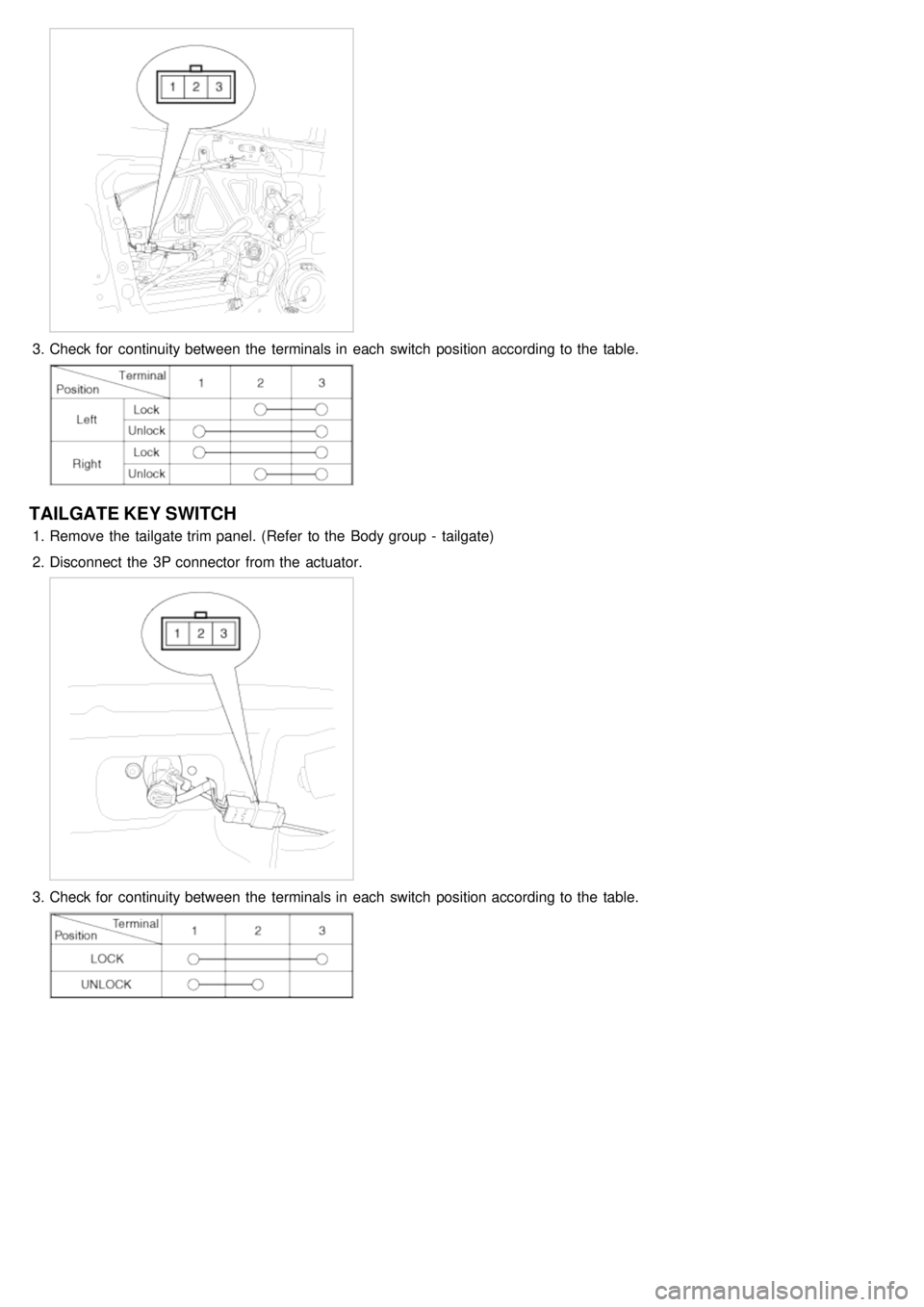
3.Check for continuity between the terminals in each switch position according to the table.
TAILGATE KEY SWITCH
1.Remove the tailgate trim panel. (Refer to the Body group - tailgate)
2. Disconnect the 3P connector from the actuator.
3.Check for continuity between the terminals in each switch position according to the table.
Page 1323 of 1575
2007 > 2.7L V6 GASOLINE >
DESCRIPTION
Power Sliding Door is an electro - mechanical system designed to provide power opening and closing of a vehicle's
sliding door through the push of a button of the transmitter key or the main control buttons on the overhead console
or the sub control buttons on the center pillar trim or inside/outside door handle switch.
The power sliding door will reverse direction of travel if resistance to movement is detected while the door is being
closed. If resistance to movement is detected while the power sliding door is being opened, the door will stop moving.
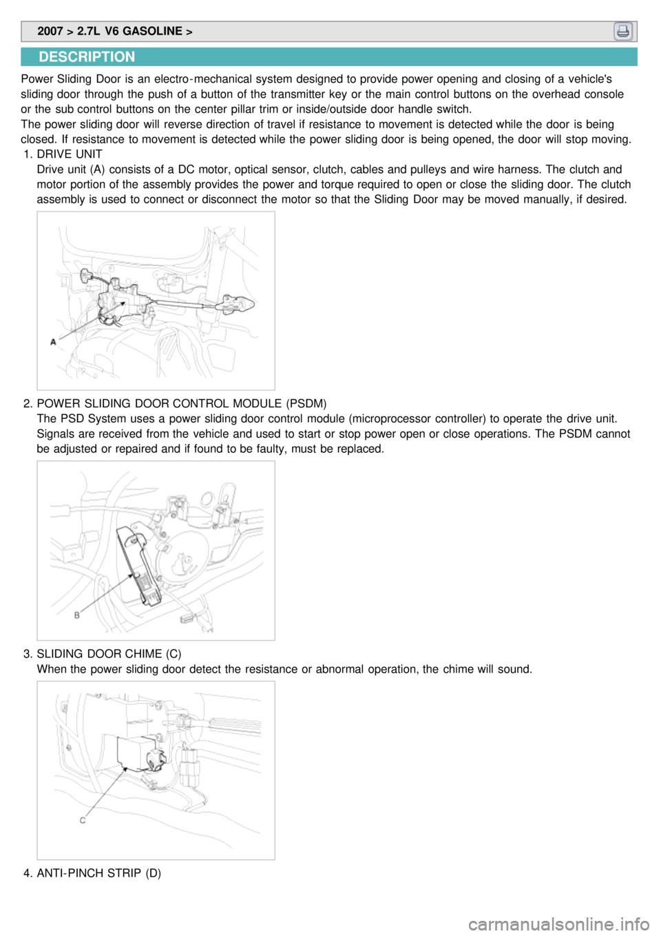
1. DRIVE UNIT
Drive unit (A) consists of a DC motor, optical sensor, clutch, cables and pulleys and wire harness. The clutch and
motor portion of the assembly provides the power and torque required to open or close the sliding door. The clutch
assembly is used to connect or disconnect the motor so that the Sliding Door may be moved manually, if desired.
2.POWER SLIDING DOOR CONTROL MODULE (PSDM)
The PSD System uses a power sliding door control module (microprocessor controller) to operate the drive unit.
Signals are received from the vehicle and used to start or stop power open or close operations. The PSDM cannot
be adjusted or repaired and if found to be faulty, must be replaced.
3.SLIDING DOOR CHIME (C)
When the power sliding door detect the resistance or abnormal operation, the chime will sound.
4.ANTI- PINCH STRIP (D)
Page 1324 of 1575

Secondary Obstacle Detection is provided by means of a contact type strip. Strip is composed of two conductive
zones separated by an air gap. When strip is compressed, conductive zones make contact, activating the switch
signal.
Copper wire is extruded through conductive material to prevent resistive buildup. Terminating resistor is molded into
end of strip to detect failures of strip.
5.OVERHEAD CONSOLE AND REMOTE CONTROL SWITCH (A)
The power sliding doors can be opened and closed automatically with the RKE and the main control button on the
overhead console.
6.DOOR LATCH (B)
The door latch contains a detent switch [C] used to detect the latch state and report the latch state to the power
sliding door module.
7.KEYLESS ENTRY (A)
Power sliding doors can be opened and closed by pressing the button on the RKE more than 0.5 sec. Open
operation shall be reserved when an additional open/close signal is received during power opening.
Page 1332 of 1575
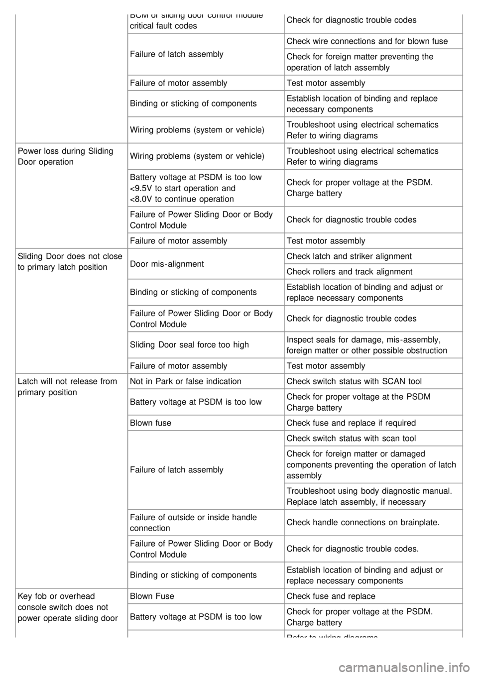
BCM or sliding door control module
critical fault codesCheck for diagnostic trouble codes
Failure of latch assembly Check wire connections and for blown fuse
Check for foreign matter preventing the
operation of latch assembly
Failure of motor assembly Test motor assembly
Binding or sticking of components Establish location of binding and replace
necessary components
Wiring problems (system or vehicle) Troubleshoot using electrical schematics
Refer to wiring diagrams
Power loss during Sliding
Door operation Wiring problems (system or vehicle)
Troubleshoot using electrical schematics
Refer to wiring diagrams
Battery voltage at PSDM is too low
<9.5V to start operation and
<8.0V to continue operation Check for proper voltage at the PSDM.
Charge battery
Failure of Power Sliding Door or Body
Control Module Check for diagnostic trouble codes
Failure of motor assembly Test motor assembly
Sliding Door does not close
to primary latch position Door mis - alignment Check latch and striker alignment
Check rollers and track alignment
Binding or sticking of components Establish location of binding and adjust or
replace necessary components
Failure of Power Sliding Door or Body
Control Module Check for diagnostic trouble codes
Sliding Door seal force too high Inspect seals for damage, mis - assembly,
foreign matter or other possible obstruction
Failure of motor assembly Test motor assembly
Latch will not release from
primary position Not in Park or false indication
Check switch status with SCAN tool
Battery voltage at PSDM is too low Check for proper voltage at the PSDM
Charge battery
Blown fuse Check fuse and replace if required
Failure of latch assembly Check switch status with scan tool
Check for foreign matter or damaged
components preventing the operation of latch
assembly
Troubleshoot using body diagnostic manual.
Replace latch assembly, if necessary
Failure of outside or inside handle
connection Check handle connections on brainplate.
Failure of Power Sliding Door or Body
Control Module Check for diagnostic trouble codes.
Binding or sticking of components Establish location of binding and adjust or
replace necessary components
Key fob or overhead
console switch does not
power operate sliding door Blown Fuse
Check fuse and replace
Battery voltage at PSDM is too low Check for proper voltage at the PSDM.
Charge battery
Refer to wiring diagrams