Page 668 of 1575
2007 > 2.7L V6 GASOLINE >
INSPECTION
1.Check the condenser fins for clogging and damage. If clogged, clean them with water, and blow them with
compressed air. If bent, gently bend them using a screwdriver or pliers.
2. Check the condenser connections for leakage, and repair or replace it, if required.
REPLACEMENT
CONDENSER ASSEMBLY
1. Recover the refrigerant with a recovery/ recycling/ charging station (Refer to HA - 8).
2. Disconnect the negative ( - ) battery terminal.
3. Remove the radiator. (Refer to EM group)
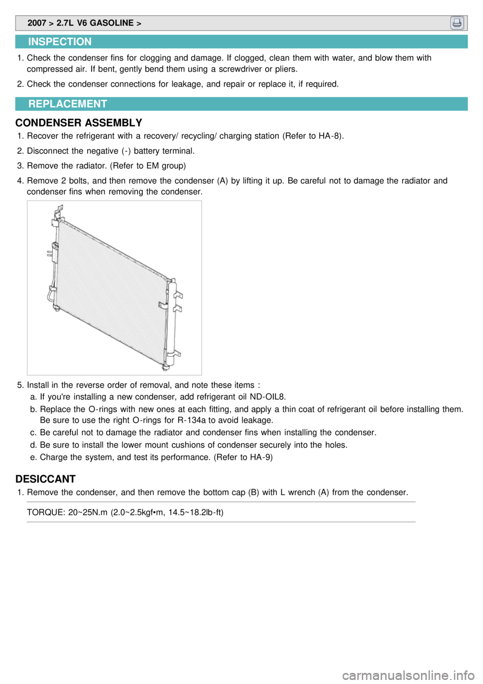
4. Remove 2 bolts, and then remove the condenser (A) by lifting it up. Be careful not to damage the radiator and
condenser fins when removing the condenser.
5.Install in the reverse order of removal, and note these items :
a. If you're installing a new condenser, add refrigerant oil ND- OIL8.
b. Replace the O - rings with new ones at each fitting, and apply a thin coat of refrigerant oil before installing them.
Be sure to use the right O - rings for R- 134a to avoid leakage.
c. Be careful not to damage the radiator and condenser fins when installing the condenser.
d. Be sure to install the lower mount cushions of condenser securely into the holes.
e. Charge the system, and test its performance. (Refer to HA - 9)
DESICCANT
1.Remove the condenser, and then remove the bottom cap (B) with L wrench (A) from the condenser.
TORQUE: 20~25N.m (2.0~2.5kgf•m, 14.5~18.2lb - ft)
Page 681 of 1575
3.Disconnect the evaporator sensor connector (A).
4. Loosen 2 screws and then remove the evaporator sensor cover(B).
5. Remove the evaporator sensor.
Take care that evaporator core pins are not bent.
6. Installation is the reverse order of removal.
Page 685 of 1575
2007 > 2.7L V6 GASOLINE >
INSPECTION
1.Ignition "ON"
2. Blow air with changing temperature to the in car sensor air inlet. Measure sensor resistance between 2 and 4
terminals.
Specification
Temperature [°C(°F)] Resistance between terminals 2and 4 (kΩ)
0 (32) 97.83 ± 2.61%
15 (59) 47.12 ± 1.45%
25 (77) 30.00 ± 1.20%
35 (95) 19.60 ± 1.44%
50 (122) 10.82 ± 2.26%
In car sensor is negative type thermistor that resistance will rise with lower temperature, and reduce with
higher temperature.
REPLACEMENT
1.Disconnect the negative ( - ) battery terminal.
2. Remove the A/C control pannel. (Refer to BD group).
3. Disconnect the connector of in - car sensor (A).Loosen the mounting 2 screws and then remove the in - car sensor
(B).
4.Installation is the reverse order of removal.
Page 689 of 1575
2007 > 2.7L V6 GASOLINE >
INSPECTION
1.Ignition "ON"
2. Using the scan tool.
3. Emit intensive light toward photo sensor using a lamp, and check the output voltage change.
4. The voltage will rise with higher intensive light and reduce with lower intensive light.
REPLACEMENT
1.Disconnect the negative ( - ) battery terminal.
2. With the ( - ) driver, remove the photo sensor (B) from the center of defrost nozzle (A).
3.Install in the reverse order of removal.
Page 694 of 1575
4.Installation is the reverse order of removal.
Take care that wire of water temperature sensor is not to be damaged
Page 698 of 1575
2007 > 2.7L V6 GASOLINE >
INSPECTION
1.Ignition "OFF"
2. Disconnect ambient temperature sensor.
3. Check the resistance of ambient temperature sensor between terminals 1 and 2 whether it is changed by changing
of the ambient temperature.
Specification
Ambient temperature [°C(°F)] Resistance between terminals 1and 2 (kΩ)
- 10(14) 164 ± 3%
0 (32) 97.5 ± 3%
10 (50) 59.6 ± 3%
20 (68) 37.5 ± 3%
4.If the measured resistance is not specification, substitute with a known- good ambient temperature sensor and
check for proper operation.
5. If the problem is corrected, replace the ambient temperature sensor.
REPLACEMENT
1.Disconnect the negative ( - ) battery terminal.
2. Remove the front bumper. (Refer to BD group)
3. Remove the ambient temperature sensor (A).
4.Installation is the reverse order of removal.
Page 702 of 1575

2007 > 2.7L V6 GASOLINE >
INSPECTION
1.Ignition "ON"
2. Using the scan tool.
3. Check the output voltage of AQS between terminals 2 and 3.
Specification
Condition Output signal Fresh/recirculation
Normal condition 4 ~ 5VFresh
Hazardous gas detection 0 ~ 1VRecirculation
4.AQS diagnosis and fail safe
Detect the open of signal for 7 seconds without choosing the AQS switch when IG on.
If 2.5V or more is detected for 3.5 seconds or more among 7 seconds, be judged the open of AQS signal.
Operate as below fail safe function, while choosing AQS.
Fail safe: Release the AQS (AQS cannot be selected), Fresh/recirculation maintains previous situation of AQS
selection.
When IG is turned ON, AQS heats for 34±5 seconds, it will output below 1.0 voltage during this time.
REPLACEMENT
1.Disconnect the negative ( - ) battery terminal.
2. Remove the front bumper (Refer to BD group).
3. Remove the AQS (A) after loosening the mounting screws (B).
4.Installation is the reverse order of removal.
Page 706 of 1575
2007 > 2.7L V6 GASOLINE >
INSPECTION
1.Ignition "ON"
2. Using the scan tool.
3. Check the frequency of humidity sensor between terminals 2 and 3.
Humidity (%) Frequency between terminals 2and 3 (Hz)
30 6976 ± 5%
50 6728 ± 5%
60 6600 ± 5%
70 6468 ± 5%
80 6330 ± 5%
90 6186 ± 5%
4. If the measured resistance is not specification, substitute with a known- good humidity sensor and check for proper
operation.
5. If the problem is corrected, replace the Humidity sensor.
REPLACEMENT
1.Disconnect the negative ( - ) battery terminal.
2. Remove the center facia lower panel (A). (Refer to BD group)
3. Disconnect the humidity sensor connector (A).
4. Loosen 2 screws and then remove the humidity sensor (B).
5.Installation is the reverse order of removal.


