Page 83 of 1575

C-
(0.0588 ~ 0.0589in.)
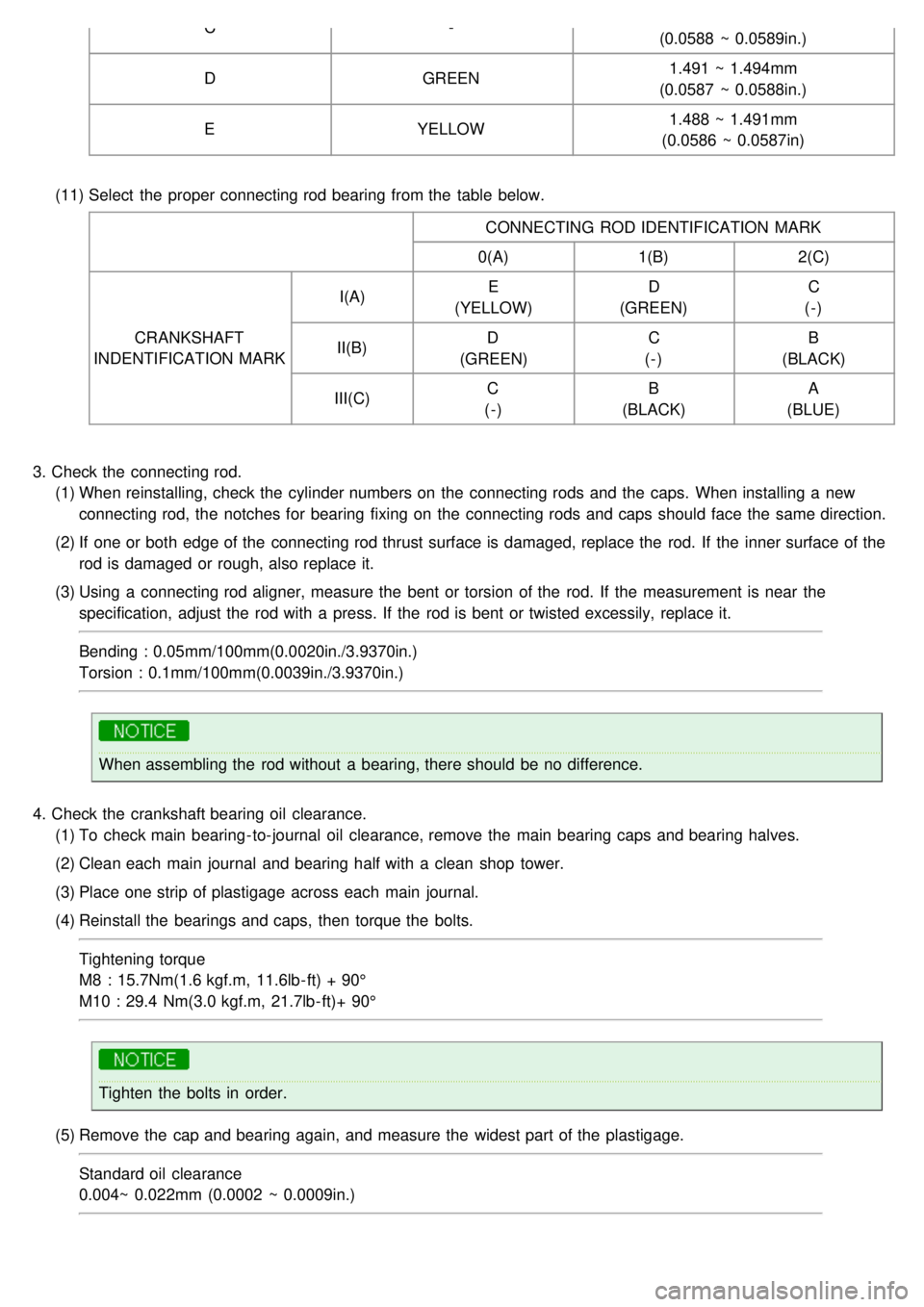
D GREEN 1.491 ~ 1.494mm
(0.0587 ~ 0.0588in.)
E YELLOW 1.488 ~ 1.491mm
(0.0586 ~ 0.0587in)
(11) Select the proper connecting rod bearing from the table below.
CONNECTING ROD IDENTIFICATION MARK
0(A) 1(B)2(C)
CRANKSHAFT
INDENTIFICATION MARK I(A)
E
(YELLOW) D
(GREEN) C
(-)
II(B) D
(GREEN) C
(-) B
(BLACK)
III(C) C
(-) B
(BLACK) A
(BLUE)
3. Check the connecting rod.
(1) When reinstalling, check the cylinder numbers on the connecting rods and the caps. When installing a new
connecting rod, the notches for bearing fixing on the connecting rods and caps should face the same direction.
(2) If one or both edge of the connecting rod thrust surface is damaged, replace the rod. If the inner surface of the
rod is damaged or rough, also replace it.
(3) Using a connecting rod aligner, measure the bent or torsion of the rod. If the measurement is near the
specification, adjust the rod with a press. If the rod is bent or twisted excessily, replace it.
Bending : 0.05mm/100mm(0.0020in./3.9370in.)
Torsion : 0.1mm/100mm(0.0039in./3.9370in.)
When assembling the rod without a bearing, there should be no difference.
4. Check the crankshaft bearing oil clearance.
(1) To check main bearing- to- journal oil clearance, remove the main bearing caps and bearing halves.
(2) Clean each main journal and bearing half with a clean shop tower.
(3) Place one strip of plastigage across each main journal.
(4) Reinstall the bearings and caps, then torque the bolts.
Tightening torque
M8 : 15.7Nm(1.6 kgf.m, 11.6lb- ft) + 90°
M10 : 29.4 Nm(3.0 kgf.m, 21.7lb- ft)+ 90°
Tighten the bolts in order.
(5) Remove the cap and bearing again, and measure the widest part of the plastigage.
Standard oil clearance
0.004~ 0.022mm (0.0002 ~ 0.0009in.)
Page 93 of 1575
When reassembling the connecting rods and the caps, ensure the front marks on them.
4. Install the CKP sensor(A).
Tightening torque
6.9 ~ 9.8Nm(0.7 ~ 1.0kgf.m, 5.1 ~ 7.2lb - ft)
5.Install main bearings.
Upper bearings have the oil grooves of the oil holes; Lower bearings do not.
(1) Aligning the bearing claw with the claw groove of the cylinder block, push in the 4 upper bearings(A).
Page 94 of 1575
(2)Aligning the bearing claw with the claw groove of the main bearing cap, push in the 4 lower bearings(B) on the
bearing caps(A).
6.Install thrust bearings.
Install the 2 thrust bearings(A) under the No.3 journal position of the cylinder block with the oil grooves facing
outward.
7.Place crankshaft(A) on the cylinder block.
8.Place main bearing caps on cylinder block.
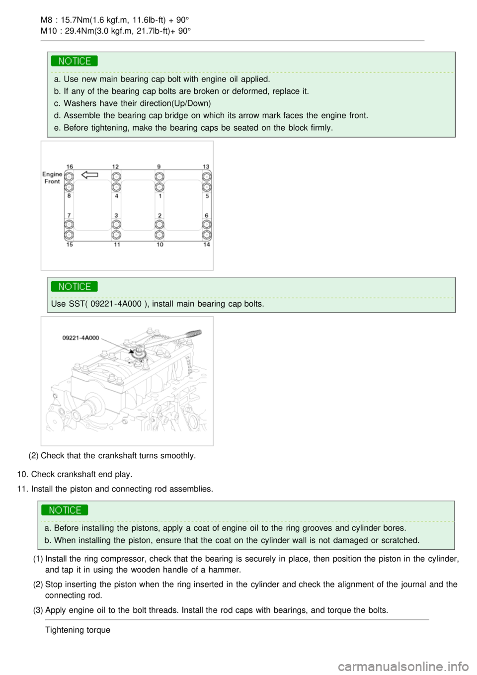
9. Install main bearing cap bolts.
(1) Install and uniformly tighten the bearing cap bolts, in two steps, in the sequence shown.
Tightening torque
Page 95 of 1575

M8 : 15.7Nm(1.6 kgf.m, 11.6lb- ft) + 90°
M10 : 29.4Nm(3.0 kgf.m, 21.7lb- ft)+ 90°
a.Use new main bearing cap bolt with engine oil applied.
b. If any of the bearing cap bolts are broken or deformed, replace it.
c. Washers have their direction(Up/Down)
d. Assemble the bearing cap bridge on which its arrow mark faces the engine front.
e. Before tightening, make the bearing caps be seated on the block firmly.
Use SST( 09221 - 4A000 ), install main bearing cap bolts.
(2) Check that the crankshaft turns smoothly.
10. Check crankshaft end play.
11. Install the piston and connecting rod assemblies.
a.Before installing the pistons, apply a coat of engine oil to the ring grooves and cylinder bores.
b. When installing the piston, ensure that the coat on the cylinder wall is not damaged or scratched.
(1) Install the ring compressor, check that the bearing is securely in place, then position the piston in the cylinder,
and tap it in using the wooden handle of a hammer.
(2) Stop inserting the piston when the ring inserted in the cylinder and check the alignment of the journal and the
connecting rod.
(3) Apply engine oil to the bolt threads. Install the rod caps with bearings, and torque the bolts.
Tightening torque
Page 96 of 1575
19.6Nm (2.0kgf.m, 14.46lb- ft) + 90°
a.Always use new connecting rod bolts.
b. Maintain downward force on the ring compressor to prevent the rings from expanding before entering
the cylinder bore.
c.Use SST(09221- 4A000), install connecting rod bearing cap bolts.
12. Install the rear oil seal case.
Tightening torque
9.80 ~ 11.76Nm (1.0 ~ 1.2kgf.m, 7.23 ~ 8.67lb- ft)
Page 98 of 1575

a.Clean the sealing face before assembling two parts.
b. Remove harmful foreign materials on the sealing face before applying sealant.
c. When applying sealant gasket, sealant must not protrude into the inside of oil pan.
d. To prevent leakage of oil, apply sealant gasket to the inner threads of the bolt holes.
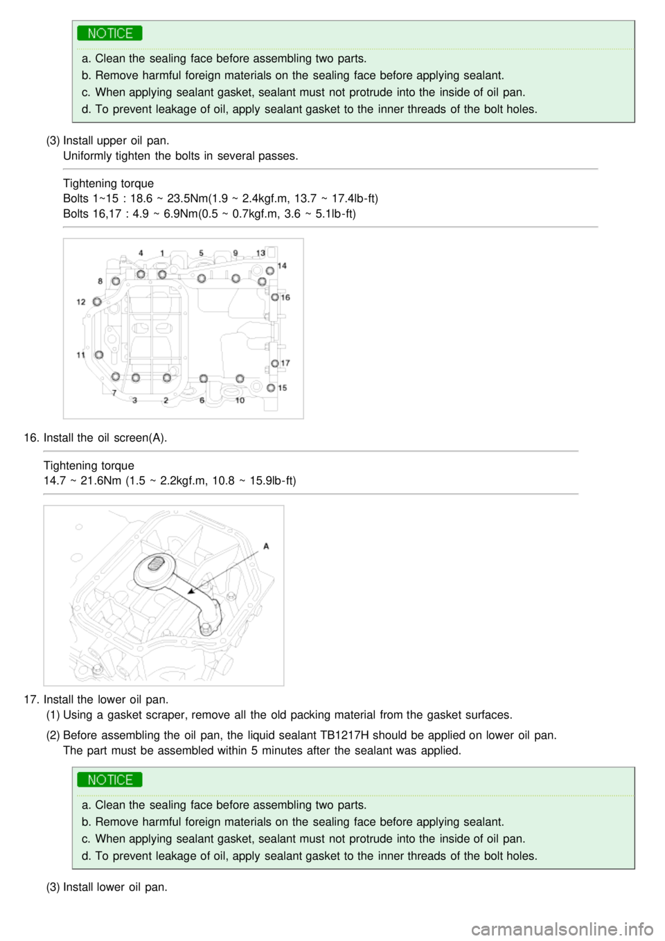
(3) Install upper oil pan.
Uniformly tighten the bolts in several passes.
Tightening torque
Bolts 1~15 : 18.6 ~ 23.5Nm(1.9 ~ 2.4kgf.m, 13.7 ~ 17.4lb- ft)
Bolts 16,17 : 4.9 ~ 6.9Nm(0.5 ~ 0.7kgf.m, 3.6 ~ 5.1lb - ft)
16. Install the oil screen(A).
Tightening torque
14.7 ~ 21.6Nm (1.5 ~ 2.2kgf.m, 10.8 ~ 15.9lb- ft)
17.Install the lower oil pan.
(1) Using a gasket scraper, remove all the old packing material from the gasket surfaces.
(2) Before assembling the oil pan, the liquid sealant TB1217H should be applied on lower oil pan.
The part must be assembled within 5 minutes after the sealant was applied.
a.Clean the sealing face before assembling two parts.
b. Remove harmful foreign materials on the sealing face before applying sealant.
c. When applying sealant gasket, sealant must not protrude into the inside of oil pan.
d. To prevent leakage of oil, apply sealant gasket to the inner threads of the bolt holes.
(3) Install lower oil pan.
Page 99 of 1575
Uniformly tighten the bolts in several passes.
Tightening torque
9.8 ~ 11.8Nm (1.0 ~ 1.2kgf.m, 7.2 ~ 8.7lb - ft)
18. Install the air conditioning compressor bracket(A). (Refer to 'HA' group)
19.Install the power steering pump bracket(A) and the knock sensor(B).
Tightening torque
18.6 ~ 23.5Nm (1.9 ~ 2.4kgf.m, 13.7 ~ 17.4lb- ft)
a.On Bank 1, the black knock sensor connector should be installed and on Bank 2, the gray one should.
Page 107 of 1575
7.Remove the radiator bracket(A, B) and the bleeder hose(C).
LH
RH
8.Separate the condenser from the radiator assembly by removing the bolts.
9. Remove the radiator assembly.
10. Remove the radiator cooling fan.
INSTALLATION
WATER PUMP
1. Install the water pump(A) and a new gasket(B) with the bolts.
Tightening torque
14.7 ~ 21.6Nm (1.5 ~ 2.2kgf.m, 10.8 ~ 15.9lb- ft)