Page 256 of 1575
![KIA CARNIVAL 2007 Workshop Manual 23Sensor Shield Knock Sensor (KS) [Bank 1], Knock Sensor (KS)
[Bank 2]
24 Camshaft Position Sensor [Bank 2] signal input Camshaft Position Sensor (CMPS) [Bank 2]
25 Camshaft Position Se KIA CARNIVAL 2007 Workshop Manual 23Sensor Shield Knock Sensor (KS) [Bank 1], Knock Sensor (KS)
[Bank 2]
24 Camshaft Position Sensor [Bank 2] signal input Camshaft Position Sensor (CMPS) [Bank 2]
25 Camshaft Position Se](/manual-img/2/57045/w960_57045-255.png)
23Sensor Shield Knock Sensor (KS) [Bank 1], Knock Sensor (KS)
[Bank 2]
24 Camshaft Position Sensor [Bank 2] signal input Camshaft Position Sensor (CMPS) [Bank 2]
25 Camshaft Position Sensor [Bank 1] signal input Camshaft Position Sensor (CMPS) [Bank 1]
26 -�y
27 -�y
28 Sensor ground HO2S [B2 / S1] [Except for LEADED]
29 Sensor ground HO2S [B2 / S2] [Euro -Ⅲ/Ⅳ]
30 Sensor ground HO2S [B1 / S1] [Except for LEADED]
31 Sensor ground HO2S [B1 / S2] [Euro -Ⅲ/Ⅳ]
32 Reference voltage (+5V) Camshaft Position Sensor (CMPS) [Bank 1]
33 Sensor ground Engine Coolant Temperature Sensor (ECTS)
34 Sensor ground Manifold Absolute Pressure Sensor (MAPS),
CVVT Oil Temperature Sensor (OTS)
35 Power ground Chassis Ground
36 Power ground Chassis Ground
37 Power ground Chassis Ground
38 Power ground Chassis Ground
39 Power ground Chassis Ground
40 Ignition Coil (Cylinder #4) control output Ignition Coil (Cylinder #4)
41 Crankshaft Position Sensor [Low] signal input Crankshaft Position Sensor (CKPS)
42 -�y
43 -�y
44 -�y
45 -�y
46 -�y
47 -�y
48 Throttle Position Sensor #1 signal input Throttle Position Sensor (TPS) #1
49 Heated Oxygen Sensor [Bank 1 / Sensor 1] signal
input HO2S (B1/S1) [Except for LEADED]
50 Heated Oxygen Sensor [Bank 1 / Sensor 2] signal
input HO2S (B1/S2) [Euro -
Ⅲ/Ⅳ]
51 Heated Oxygen Sensor [Bank 2 / Sensor 1] signal
input HO2S (B2/S1) [Except for LEADED]
52 Heated Oxygen Sensor [Bank 2 / Sensor 2] signal
input HO2S (B2/S2) [Euro -
Ⅲ/Ⅳ]
53 Knock Sensor (KS) [Bank 2] [High] signal input Knock Sensor (KS) [Bank 2]
54 Knock Sensor (KS) [Bank 2] [Low] signal input Knock Sensor (KS) [Bank 2]
55 Knock Sensor (KS) [Bank 1] [Low] signal input Knock Sensor (KS) [Bank 1]
56 Knock Sensor (KS) [Bank 1] [High] signal input Knock Sensor (KS) [Bank 1]
57 Throttle Position Sensor #2 signal input Throttle Position Sensor (TPS) #2
58 Sensor ground Throttle Position Sensor (TPS) #2
59 -�y
60 Ignition Coil (Cylinder #2) control output Ignition Coil (Cylinder #2)
Page 260 of 1575
![KIA CARNIVAL 2007 Workshop Manual 64A/C Compressor Relay control
output A/C OFF
DCBattery Voltage
13.97V
A/C ON Max. 1.0V175mV
65 Cooling Fan [Low] control output Fan OFF
DCBattery Voltage
13.77V
Fan ON Max. 1.0V175mV
66 Cooli KIA CARNIVAL 2007 Workshop Manual 64A/C Compressor Relay control
output A/C OFF
DCBattery Voltage
13.97V
A/C ON Max. 1.0V175mV
65 Cooling Fan [Low] control output Fan OFF
DCBattery Voltage
13.77V
Fan ON Max. 1.0V175mV
66 Cooli](/manual-img/2/57045/w960_57045-259.png)
64A/C Compressor Relay control
output A/C OFF
DCBattery Voltage
13.97V
A/C ON Max. 1.0V175mV
65 Cooling Fan [Low] control output Fan OFF
DCBattery Voltage
13.77V
Fan ON Max. 1.0V175mV
66 Cooling Fan [High] control output Fan OFF
DCBattery Voltage
13.57V
Fan ON Max. 1.0V- 25mV
67 Variable Intake Solenoid Valve
#2 control output Active
DCMax. 1.0 V
13.77
Inactive Battery Voltage- 25mV
68 Throttle Position Sensor signal
(PWM) output
Idle
PulseHi: Battery Voltage
13.37V
Lo: 0 ~ 0.5 V - 25mV
69 Cruise "MAIN" lamp control
output Cruise OFF
DCBattery Voltage
12.37V
Cruise ON Max. 1.0V- 25mV
70 Fuel Pump Relay control output Relay OFF
DCBattery Voltage
12.57V
Relay ON Max. 1.0V- 25mV
71 Variable Intake Solenoid Valve
#1 control output Active
DCMax. 1.0 V
175mV
Inactive Battery Voltage13.77V
72 Immobilizer lamp control output Lamp OFF
DCBattery Voltage
12.77V
Lamp ON Max. 1.0V- 25mV
73 - �y�y �y �y
74 - �y�y �y �y
75 - �y�y �y �y
76 - �y�y �y �y
77 - �y�y �y �y
78 Purge Control Solenoid Valve
control output Inactive
PulseHi: Battery Voltage
13.83V
Active Lo: Max. 1.0V31.54mV
79 Wheel Speed Sensor [Low]
signal input �y
�y �y �y
80 Wheel Speed Sensor [High]
signal input �y
�y �y �y
CONNECTOR [C151- 2] Pin
No. Description
ConditionType LevelTest Result
1 ETC Motor [- ] control output IdlePulseHi: Battery Voltage
14.07V
Lo: Max . 1.0V - 125mV
2 ETC Motor [+] control output IdlePulseHi: Battery Voltage
14.07V
Lo: Max . 1.0V - 325mV
3 - �y�y �y �y
4 CVVT Oil Temperature Sensor
signal input Idle
Analog 0 ~ 5.0V 282mV at 96°C
5 - �y�y �y �y
6 - �y�y �y �y
7 Engine Coolant Temperature
Sensor signal input Idle
Analog 0 ~ 5.0V 1.88V
Page 285 of 1575
CVVT Oil Temperature Sensor(OTS)
Page 286 of 1575
2007 > 2.7L V6 GASOLINE >
INSPECTION
FUNCTION AND OPERATION PRICIPLE
The CVVT Oil Temperature Sensor (OTS) is a negative coefficient thermistor used by the PCM tl measure engine oil
temperature for the purpose of adjusting CVVT calculations.
SPECIFICATION
Temperature Resistance (kΩ)
°C °F
- 40 - 4052.0
- 20 -416.5
0 32 6.0
20 682.45
40 104 1.10
60 1400.544
80 1760.290
100 2120.164
120 2480.099
CIRCUIT DIAGRAM
Page 303 of 1575

2007 > 2.7L V6 GASOLINE >
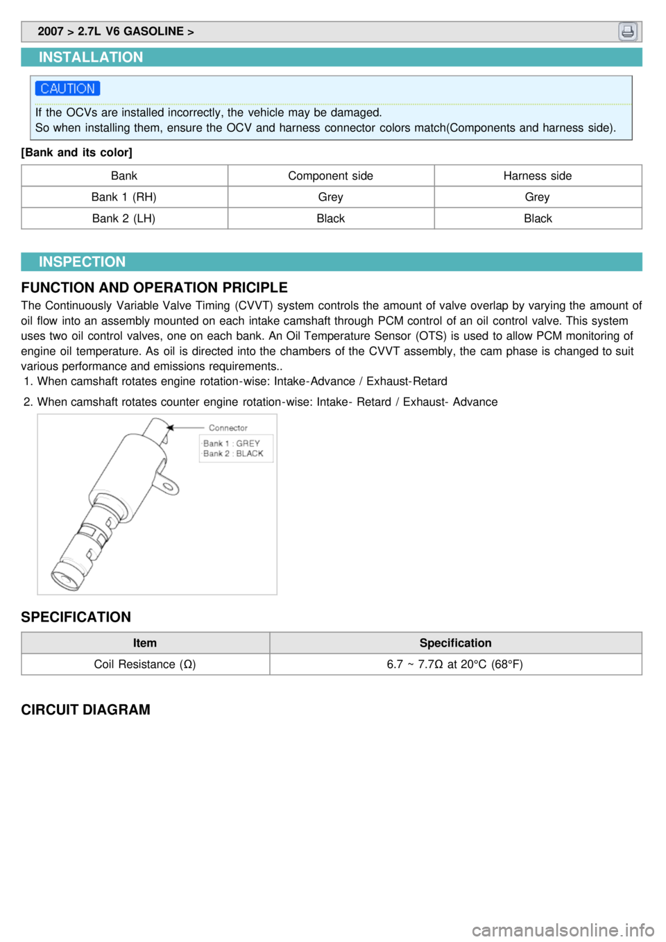
INSTALLATION
If the OCVs are installed incorrectly, the vehicle may be damaged.
So when installing them, ensure the OCV and harness connector colors match(Components and harness side).
[Bank and its color] Bank Component side Harness side
Bank 1 (RH) GreyGrey
Bank 2 (LH) BlackBlack
INSPECTION
FUNCTION AND OPERATION PRICIPLE
The Continuously Variable Valve Timing (CVVT) system controls the amount of valve overlap by varying the amount of
oil flow into an assembly mounted on each intake camshaft through PCM control of an oil control valve. This system
uses two oil control valves, one on each bank. An Oil Temperature Sensor (OTS) is used to allow PCM monitoring of
engine oil temperature. As oil is directed into the chambers of the CVVT assembly, the cam phase is changed to suit
various performance and emissions requirements.. 1. When camshaft rotates engine rotation- wise: Intake- Advance / Exhaust- Retard
2. When camshaft rotates counter engine rotation- wise: Intake- Retard / Exhaust- Advance
SPECIFICATION
Item Specification
Coil Resistance (Ω) 6.7 ~ 7.7Ω at 20°C (68°F)
CIRCUIT DIAGRAM
Page 328 of 1575

2007 > 2.7L V6 GASOLINE >
SPECIFICATION
Item F4A51
Torque converter type 3 - element, 1 - stage, 2 - phase type
Transaxle type 4 - speed forward, 1 - speed reverse
Engine displacement 2.7L GSL
Gear ratio 1st
2.842
2nd 1.495
3rd 1.000
4th 0.731
Reverse 2.720
Final gear ratio 4.520
Shift pattern Variable
Shift range 4range ( P- R- N- D) + Sports mode
Shift range valve PWM ; 5EA(Duty control) , VFS
Planetary gear 2EA(Output planetary/Overdrive planetary)
Clutch 3EA
Brake 2EA
OWC 1EA
TIGHTENING TORQUE ITEM Nmkgf·m lb- ft
Control cable nut 8 ~ 120.8 ~ 1.2 5.8 ~ 8.6
Input shaft speed sensor 10 ~ 121.0 ~1.2 7 ~ 8
Output shaft speed sensor 10 ~ 121.0 ~1.2 7 ~ 8
Manual control lever 18 ~ 251.8 ~ 2.5 13 ~ 18
Transaxle range switch 10 ~ 121.0 ~1.2 7 ~ 8
Valve body cover 10 ~ 121.0 ~1.2 7 ~ 8
Valve body mounting bolt 10 ~ 121.0 ~1.2 7 ~ 8
Oil temperature sensor 10 ~ 121.0 ~1.2 7 ~ 8
Oil filler plug 29 ~ 342.9 ~ 3.421.4 ~ 25.1
Oil drain plug 40 ~ 504.0 ~ 5.0 29 ~ 36
Solenoid valve support 5 ~ 70.5 ~ 0.7 4 ~ 5
Pressure check plug 8 ~ 100.8 ~ 1.0 6 ~ 7
Transaxle mounting sub bracket nut 60 ~ 806.0 ~ 8.0 43 ~ 58
Transaxle mounting bracket bolts 40 ~ 554.0 ~ 5.5 29 ~ 40
Transaxle mounting insulator bolt 90 ~ 1109.0 ~ 1165 ~ 80
Transaxle and engine mounting bolt 65 ~ 856.5 ~ 8.5 47 ~ 61.5
Drive plate bolt 46 ~ 534.6 ~ 5.333.3 ~ 38.3
Page 335 of 1575

A31N.A -- - -
A32 A/C Pressure Analog -- - --
A34 N.A -- - -
A36 N.A -- - -
A37 N.A -- - -
A41 CAN_HI Recessive
Dominant Pulse
2.0 ~ 3.0 V
2.75 ~ 4.5 V 3.85V
2.5V
A42 CAN_LO Recessive
Dominant Pulse
2.0 ~ 3.0 V
0.5 ~ 2.25 V 2.55V
1.34V
A60 A/T PWR Source IG Off
IG On
IG. Key On
IG. Key Off Idle
Key Off from Idle
Fuse 1/2/3
Removal Condition DC
Voltage Max. 0.5 V
V_BAT
MAX. +/ - 75V (ECU GND)
MAX. +/ - 75V (ECU GND)
MAX. +/ - 75V (ECU GND)
MAX. +/ - 75V (ECU GND)
MAX. +/ - 75V (ECU GND) 0V
11.9V
+30V / - 10V or less ↑
W/H Open DTC Spec : P0888DTC : P0888
A73 Shift Position
Signal(To Cluster) Running
1 gear
2 gear
3 gear
4 gear
5 gear Pulse
Duty ↑
↑
↑
↑ HI : V_BAT
LO : Max. 1.0V
Freq.: 50±2Hz (Reference) 12.5±2%
27.5±2%
42.5±2%
57.5±2%
72.5±2% N.A
Sports
mode
B03 UD Solenoid Shifting
Pulse HI : V_BAT
LO : Max. 1.0V
Vpeak : Max. 70V 14.4V
0.35V
56.3V
W/H Open DTC Spec : P0755DTC : P0755
B05 N.A -- - -
B06 Oil temperature
sensor_ATM Idle
Analog 0.5V ~ 4.5V 4.4V
3.1V16Hz
B09 Output speed sensor 30kph
Pulse HI : Min. 4.0V
LO : Max. 1.0V 5.08V
0.34V
W/H Open DTC Spec : P0722DTC : P0722
B10 Input speed sensor Idle
Pulse HI : Min. 4.0V
LO : Max. 1.0V 5.06V
0.35V
630Hz
W/H Open DTC Spec : P0717DTC : P0717
B20 N.A -- - -
B22 LR Solenoid Shifting
Pulse HI : V_BAT
LO : Max. 1.0V
Vpeak : Max. 70V 13.9V
0.38V
56.1V
W/H Open DTC Spec : P0750DTC : P0750
B26 N.A -- - -
B27 N.A -- - -
B33 GND_Sensor Idle
DC
Voltage Max. 50 mV
13mV
WTS &
OTS_ATM
W/H Open DTC Spec : P0118/ 1115DTC : P0118/
P1115
B42 OD Solenoid Shifting
Pulse HI : V_BAT
LO : Max. 1.0V
Vpeak : Max. 70V 15.4V
0.45V
56.3V
Page 363 of 1575

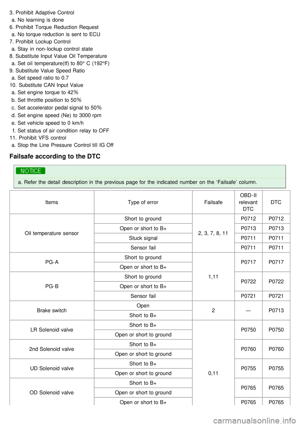
3. Prohibit Adaptive Controla. No learning is done
6. Prohibit Torque Reduction Request a. No torque reduction is sent to ECU
7. Prohibit Lockup Control a. Stay in non- lockup control state
8. Substitute Input Value Oil Temperature a. Set oil temperature(tf) to 80° C (192°F)
9. Substitute Value Speed Ratio a. Set speed ratio to 0.7
10. Substitute CAN Input Value a. Set engine torque to 42 �Ë
b. Set throttle position to 50�Ë
c. Set accelerator pedal signal to 50 �Ë
d. Set engine speed (Ne) to 3000 rpm
e. Set vehicle speed to 0 km/h
f. Set status of air condition relay to OFF
11. Prohibit VFS control a. Stop the Line Pressure Control till IG Off
Failsafe according to the DTC
a.Refer the detail description in the previous page for the indicated number on the ‘Failsafe’ column.
Items Type of errorFailsafeOBD - II
relevant DTC DTC
Oil temperature sensor Short to ground
2, 3, 7, 8, 11P0712
P0712
Open or short to B+ P0713P0713
Stuck signal P0711P0711
Sensor fail P0711P0711
PG- A Short to ground
1,11P0717
P0717
Open or short to B+
PG- B Short to ground
P0722P0722
Open or short to B+
Sensor fail P0721P0721
Brake switch Open
2―P0713
Short to B+
LR Solenoid valve Short to B+
0,11P0750
P0750
Open or short to ground
2nd Solenoid valve Short to B+
P0760P0760
Open or short to ground
UD Solenoid valve Short to B+
P0755P0755
Open or short to ground
OD Solenoid valve Short to B+
P0765P0765
Open or short to ground
Open or short to B+ P0765P0765