Page 1380 of 1575
4.Select the sensor output. And then check the clutch feedback sensor output while operating power tailgate in
power mode.
※ Above voltage and numerical value may be different from the real value.
5. Change the drive unit, if there is no change during operation.
REPLACEMENT
1.Disconnect the negative ( - ) battery terminal.
2. Remove the third, fourth seat (Refer to the Body group - seat)
3. Remove the D pillar and luggage side trim (Refer to the Body group - Interior trim).
4. Use a small screw driver to loosen clip (A). But do not remove power tailgate push rod (B).
5.Remove the power tail gate motor mounting bolts (3EA) and connectors (4EA). And then remove the power tail
gate drive unit(A).
TORQUE : 22- 27N.m(2.2- 2.7Kg.m)
Page 1384 of 1575
2007 > 2.7L V6 GASOLINE >
INSPECTION
1.Check the power tail gate control module input/output value by using the diagnostic tool. If the operation of tailgate
control module is abnormal, replace anti pinch strip control module.
2. When checking the anti pinch strip operation, select a vehicle type and "POWER SLIDING/TAILGATE" menu.
3.Select "POWER TAILGATE".
4.Select the sensor output. And then check the anti pinch strip sensor output while operating power tailgate in power
mode.
※ Above voltage and numerical value may be different from the real value.
5. Change the anti pinch strip sensor, if there is no change from OFF to ON during operation.
REPLACEMENT
1.Disconnect the negative ( - ) battery terminal.
2. Remove the tail gate trim (Refer to the Body group - tail gate).
3. Remove the anti- pinch strip sensor connector (A).
Page 1385 of 1575
4.Remove the left and right side anti- pinch strip sensor (B) after removing the screws (5EA).
5.Installation is the reverse of removal. Part (C) has to be assembled using the cloth.
Page 1387 of 1575
2007 > 2.7L V6 GASOLINE >
INPECTION
1.Check the power tail gate control module input/output value by using the diagnostic tool. If the operation of tailgate
control module is abnormal, replace power latch.
2. To check the power latch operation, select a vehicle type and "POWER SLIDING/TAILGATE" menu.
3.Select "POWER TAILGATE".
4.Select the sensor output. And then check the cinch feedback and unlatch feedback output while operating power
tailgate in power mode.
※ Above voltage and numerical value may be different from the real value.
5. Change the anti pinch strip sensor, if there is no change during operation.
REPLACEMENT
1.Disconnect the negative ( - ) battery terminal.
2. Remove the tail gate trim (Refer to the Body group - tail gate).
3. Remove the tail gate handle rod, actuator rod and key rod.
4. Remove the unlatch actuator assembly (A) after removing the connector and nuts (3EA).
Page 1391 of 1575
3.Select the "POWER TAILGATE" menu to check.
4.Select the sensor output. And then check the power tailgate local switch output value changed by the controlling
PTG.
5.If there is no input/output change from OFF to ON during PTG operation, change the power tailgate switch.
REPLACEMENT
OVERHEAD CONSOLE SWITCH
1. Disconnect the negative ( - ) battery terminal.
2. Open the sunglass case cover from the overhead console then remove the 2 screws holding the overhead console
(A). And then disconnect the connector (B).
Page 1431 of 1575
2007 > 2.7L V6 GASOLINE >
REPLACEMENT
1.Disconnect the negative ( - ) battery terminal.
2. Remove the front bumper cover. (Refer to Body group - Front bumper)
3. Remove the washer hose, the washer motor connector (A) and washer level sensor connector (C).
4. Remove the washer reservoir after removing 2 bolts and 1 step bolt.
5.Installation is the reverse of removal.
INSPECTION
1.With the washer motor connected to the reservoir tank, fill the reservoir tank with water.
2. Connect positive (+) battery cables to terminal 2 and negative ( - ) battery cables to terminal 1 respectively.
3. Check that the motor operates normally and the washer motor runs and water sprays from the front nozzles. If they
are abnormal, replace the washer motor.
Page 1433 of 1575
Page 1434 of 1575

2007 > 2.7L V6 GASOLINE >
DESCRIPTION
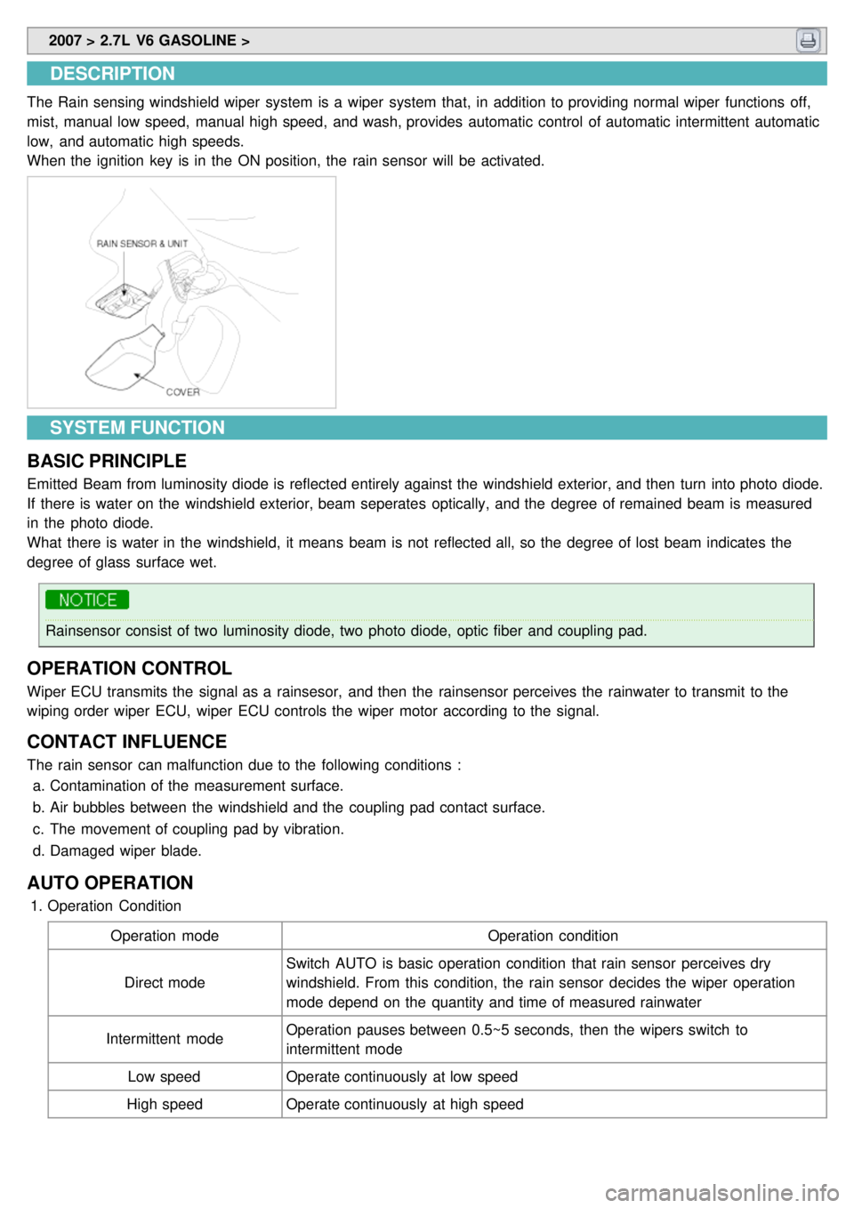
The Rain sensing windshield wiper system is a wiper system that, in addition to providing normal wiper functions off,
mist, manual low speed, manual high speed, and wash, provides automatic control of automatic intermittent automatic
low, and automatic high speeds.
When the ignition key is in the ON position, the rain sensor will be activated.
SYSTEM FUNCTION
BASIC PRINCIPLE
Emitted Beam from luminosity diode is reflected entirely against the windshield exterior, and then turn into photo diode.
If there is water on the windshield exterior, beam seperates optically, and the degree of remained beam is measured
in the photo diode.
What there is water in the windshield, it means beam is not reflected all, so the degree of lost beam indicates the
degree of glass surface wet.
Rainsensor consist of two luminosity diode, two photo diode, optic fiber and coupling pad.
OPERATION CONTROL
Wiper ECU transmits the signal as a rainsesor, and then the rainsensor perceives the rainwater to transmit to the
wiping order wiper ECU, wiper ECU controls the wiper motor according to the signal.
CONTACT INFLUENCE
The rain sensor can malfunction due to the following conditions : a. Contamination of the measurement surface.
b. Air bubbles between the windshield and the coupling pad contact surface.
c. The movement of coupling pad by vibration.
d. Damaged wiper blade.
AUTO OPERATION
1.Operation Condition
Operation mode Operation condition
Direct mode Switch AUTO is basic operation condition that rain sensor perceives dry
windshield. From this condition, the rain sensor decides the wiper operation
mode depend on the quantity and time of measured rainwater
Intermittent mode Operation pauses between 0.5~5 seconds, then the wipers switch to
intermittent mode
Low speed Operate continuously at low speed
High speed Operate continuously at high speed