Page 1435 of 1575
2.Safety Function
a. When there is an ice in the sensing field, the rain sensor cannot recognize the correct working condition.
Do not operate the rain sensing wipers unless the windshield is completely clear of ice and snow.
b. Glass damage : rain sensor cannot perceive the damaged windshield within the sensing field.
c. The rain senson will not operate properly if detached from the windsheld.
d. If the wiper ECU does not transmit any effective data in 5 seconds, the rain sensor turns off LED.
e. If the intermittent wiper signal is interrupted for >2 sec, the wipers are moved to the parking position.
f. If a rain sensor signal communication error lasts for > 5sec, the wipers are moved into the parking position.
g. If the rain sensor transmits an error to the wiper ECU, the wiper ECU stops the AUTO function after 4.5
seconds.
Page 1436 of 1575

2007 > 2.7L V6 GASOLINE >
REMOVAL
The rain sensor may not operate proprly if contaminated. Protect the rain sensor surface by not removing the
cover until installation time. The coupling pad on the rain sensor surface has adhesive strength. Take care when
installing the sensor. If the sensor is separated from the windshield by force, the sensor or windshield may be
damaged. Take care when removing the sensor.
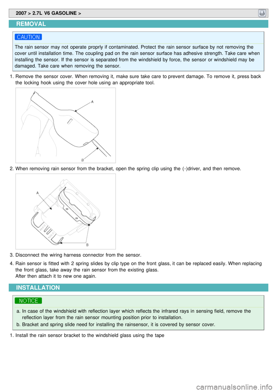
1. Remove the sensor cover. When removing it, make sure take care to prevent damage. To remove it, press back
the locking hook using the cover hole using an appropriate tool.
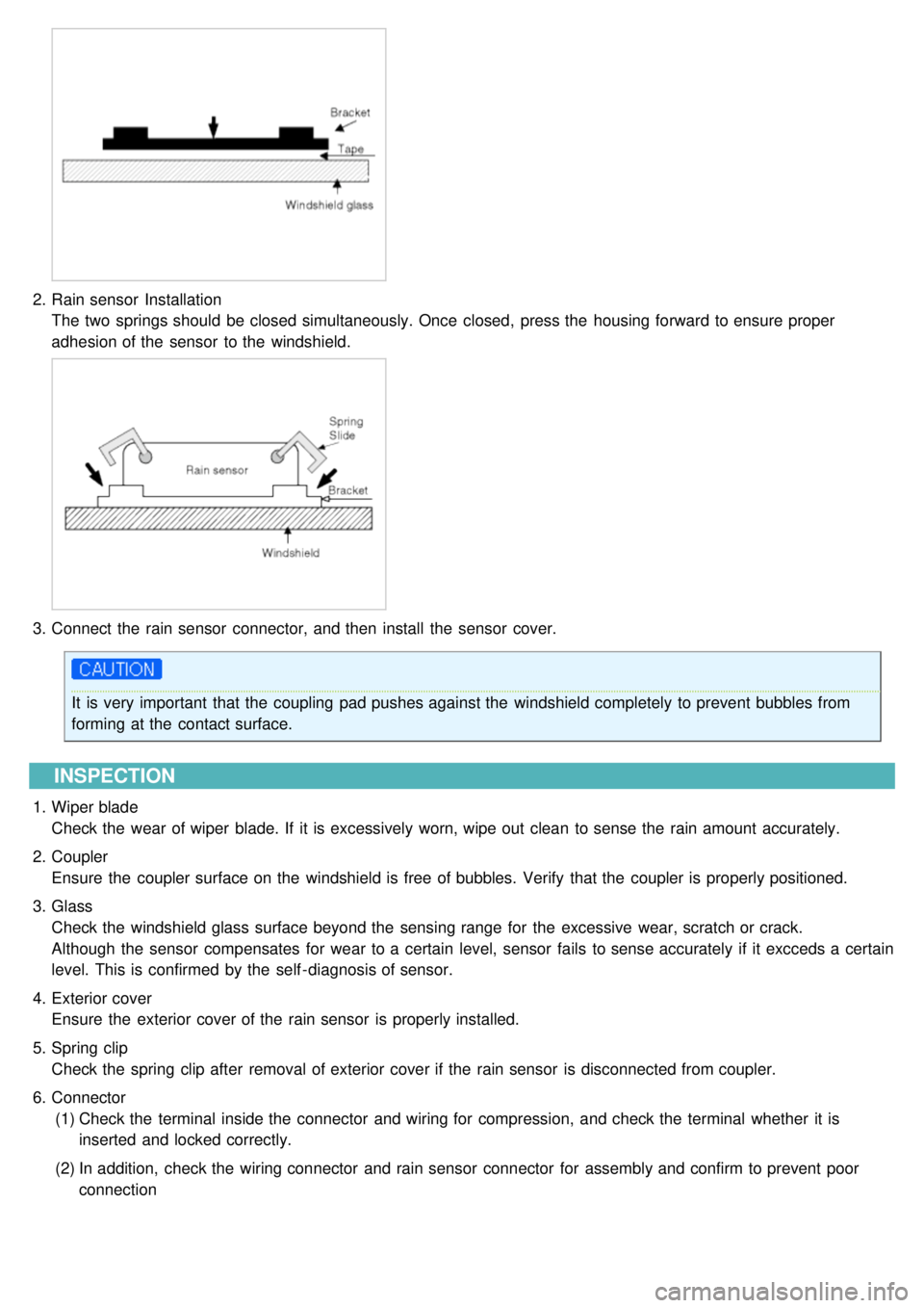
2.When removing rain sensor from the bracket, open the spring clip using the ( - )driver, and then remove.
3.Disconnect the wiring harness connector from the sensor.
4. Rain sensor is fitted with 2 spring slides by clip type on the front glass, it can be replaced easily. When replacing
the front glass, take away the rain sensor from the existing glass.
After then attach it to new one again.
INSTALLATION
a.In case of the windshield with reflection layer which reflects the infrared rays in sensing field, remove the
reflection layer from the rain sensor mounting position prior to installation.
b. Bracket and spring slide need for installing the rainsensor, it is covered by sensor cover.
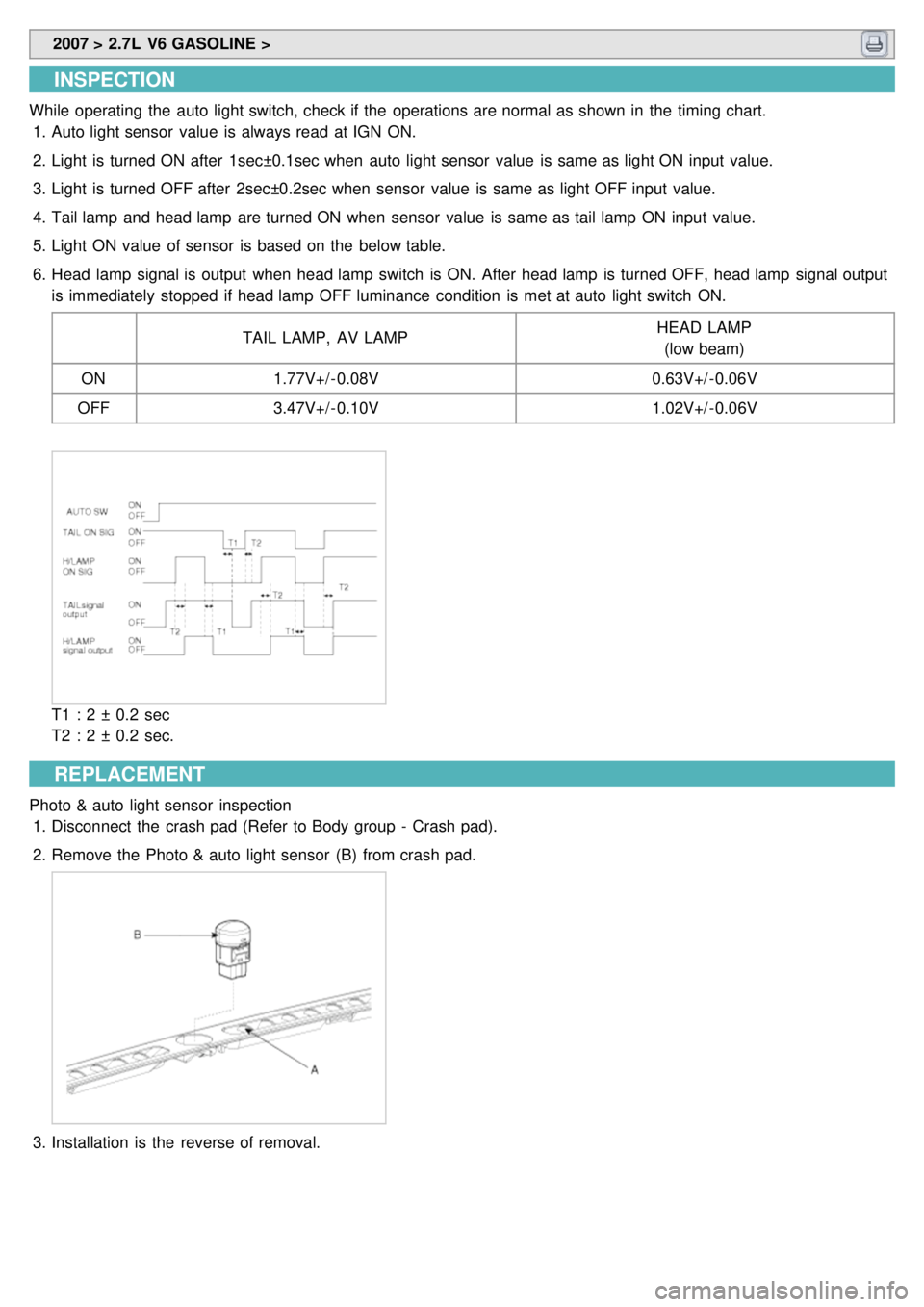
1. Install the rain sensor bracket to the windshield glass using the tape
Page 1437 of 1575

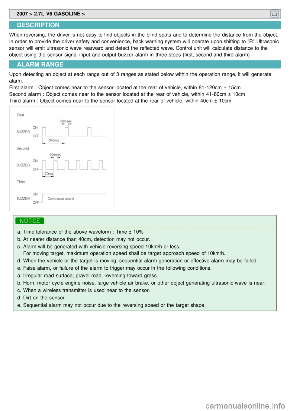
2.Rain sensor Installation
The two springs should be closed simultaneously. Once closed, press the housing forward to ensure proper
adhesion of the sensor to the windshield.
3.Connect the rain sensor connector, and then install the sensor cover.
It is very important that the coupling pad pushes against the windshield completely to prevent bubbles from
forming at the contact surface.
INSPECTION
1.Wiper blade
Check the wear of wiper blade. If it is excessively worn, wipe out clean to sense the rain amount accurately.
2. Coupler
Ensure the coupler surface on the windshield is free of bubbles. Verify that the coupler is properly positioned.
3. Glass
Check the windshield glass surface beyond the sensing range for the excessive wear, scratch or crack.
Although the sensor compensates for wear to a certain level, sensor fails to sense accurately if it excceds a certain
level. This is confirmed by the self - diagnosis of sensor.
4. Exterior cover
Ensure the exterior cover of the rain sensor is properly installed.
5. Spring clip
Check the spring clip after removal of exterior cover if the rain sensor is disconnected from coupler.
6. Connector
(1) Check the terminal inside the connector and wiring for compression, and check the terminal whether it is
inserted and locked correctly.
(2) In addition, check the wiring connector and rain sensor connector for assembly and confirm to prevent poor
connection
Page 1447 of 1575
2007 > 2.7L V6 GASOLINE >
DESCRIPTION
The electrochromatic rear view mirror detects the ambient light using a built- in sensor and adjusts the reflectability of
the mirror to prevent excess light (such as the light emitted by a following vehicle's headlights) from reaching the
driver's eyes during night driving. To allow for maximum vision while backing up, the electrochromatic functionality of
the mirror is deactivated whenever the transaxle is in 'R' range.
1.The front sensor sees if the brightness of the surroundings is low enough for the mirror to operate its function.
2. The rearward looking sensor detects glaring of the reflecting light from a following vehicle.
3. The ECM is darkened to the level as determined by the rearward looking sensor. When the glaring is no longer
detected, the mirror stops functioning.
Page 1448 of 1575
2007 > 2.7L V6 GASOLINE >
INSPECTION
Check it by the procedure below to see if the function of the ECM is normal.
1. Turn the ignition key to the "ON" position.
2. Cover the front sensor to stop functioning.
3. Shine a light at the rear sensor.
4. The ECM should be darkened as soon as the rear sensor detects the light.
If this test is performed in daytime, the mirror may be darkened as soon as the looking sensor is covered.
5. When the reverse gear is engaged, the ECM should not be darkened.
REPLACEMENT
1.Push the inside rear view mirror base down to remove the inside rear view mirror assembly (A) after removing the
mirror wire cover.
Take care not to damage the mounting bracket during removal.
2.Installation is the reverse of removal.
Page 1495 of 1575
Page 1496 of 1575

2007 > 2.7L V6 GASOLINE >
INSPECTION
While operating the auto light switch, check if the operations are normal as shown in the timing chart.
1. Auto light sensor value is always read at IGN ON.
2. Light is turned ON after 1sec±0.1sec when auto light sensor value is same as light ON input value.
3. Light is turned OFF after 2sec±0.2sec when sensor value is same as light OFF input value.
4. Tail lamp and head lamp are turned ON when sensor value is same as tail lamp ON input value.
5. Light ON value of sensor is based on the below table.
6. Head lamp signal is output when head lamp switch is ON. After head lamp is turned OFF, head lamp signal output
is immediately stopped if head lamp OFF luminance condition is met at auto light switch ON.
TAIL LAMP, AV LAMP HEAD LAMP
(low beam)
ON 1.77V+/ - 0.08V 0.63V+/ - 0.06V
OFF 3.47V+/ - 0.10V 1.02V+/ - 0.06V
T1 : 2 ± 0.2 sec
T2 : 2 ± 0.2 sec.
REPLACEMENT
Photo & auto light sensor inspection
1. Disconnect the crash pad (Refer to Body group - Crash pad).
2. Remove the Photo & auto light sensor (B) from crash pad.
3.Installation is the reverse of removal.
Page 1533 of 1575

2007 > 2.7L V6 GASOLINE >
DESCRIPTION
When reversing, the driver is not easy to find objects in the blind spots and to determine the distance from the object.
In order to provide the driver safety and convenience, back warning system will operate upon shifting to "R" Ultrasonic
sensor will emit ultrasonic wave rearward and detect the reflected wave. Control unit will calculate distance to the
object using the sensor signal input and output buzzer alarm in three steps (first, second and third alarm).
ALARM RANGE
Upon detecting an object at each range out of 3 ranges as stated below within the operation range, it will generate
alarm.
First alarm : Object comes near to the sensor located at the rear of vehicle, within 81- 120cm ± 15cm
Second alarm : Object comes near to the sensor located at the rear of vehicle, within 41- 80cm ± 10cm
Third alarm : Object comes near to the sensor located at the rear of vehicle, within 40cm ± 10cm
a.Time tolerance of the above waveform : Time ± 10%
b. At nearer distance than 40cm, detection may not occur.
c. Alarm will be generated with vehicle reversing speed 10km/h or less.
For moving target, maximum operation speed shall be target approach speed of 10km/h.
d. When the vehicle or the target is moving, sequential alarm generation or effective alarm may be failed.
e. False alarm, or failure of the alarm to trigger may occur in the following conditions.
a. Irregular road surface, gravel road, reversing toward grass.
b. Horn, motor cycle engine noise, large vehicle air brake, or other object generating ultrasonic wave is near.
c. When a wireless transmitter is used near to the sensor.
d. Dirt on the sensor.
e. Sequential alarm may not occur due to the reversing speed or the target shape.