Page 1261 of 1575

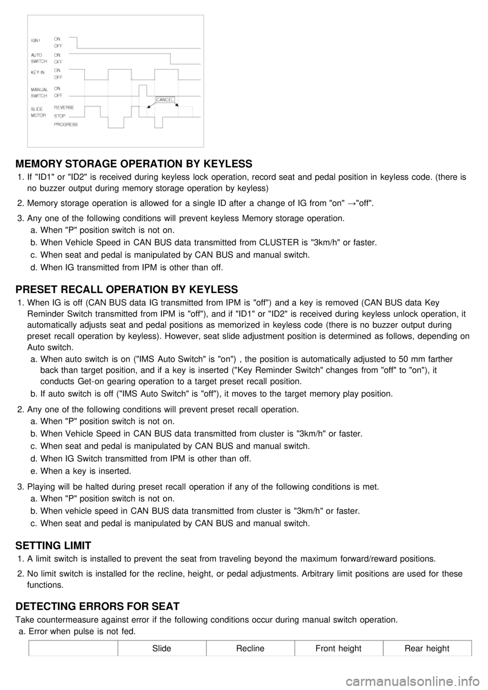
MEMORY STORAGE OPERATION BY KEYLESS
1.If "ID1" or "ID2" is received during keyless lock operation, record seat and pedal position in keyless code. (there is
no buzzer output during memory storage operation by keyless)
2. Memory storage operation is allowed for a single ID after a change of IG from "on" →"off".
3. Any one of the following conditions will prevent keyless Memory storage operation.
a. When "P" position switch is not on.
b. When Vehicle Speed in CAN BUS data transmitted from CLUSTER is "3km/h" or faster.
c. When seat and pedal is manipulated by CAN BUS and manual switch.
d. When IG transmitted from IPM is other than off.
PRESET RECALL OPERATION BY KEYLESS
1.When IG is off (CAN BUS data IG transmitted from IPM is "off") and a key is removed (CAN BUS data Key
Reminder Switch transmitted from IPM is "off"), and if "ID1" or "ID2" is received during keyless unlock operation, it
automatically adjusts seat and pedal positions as memorized in keyless code (there is no buzzer output during
preset recall operation by keyless). However, seat slide adjustment position is determined as follows, depending on
Auto switch.
a. When auto switch is on ("IMS Auto Switch" is "on") , the position is automatically adjusted to 50 mm farther
back than target position, and if a key is inserted ("Key Reminder Switch" changes from "off" to "on"), it
conducts Get- on gearing operation to a target preset recall position.
b. If auto switch is off ("IMS Auto Switch" is "off"), it moves to the target memory play position.
2. Any one of the following conditions will prevent preset recall operation.
a. When "P" position switch is not on.
b. When Vehicle Speed in CAN BUS data transmitted from cluster is "3km/h" or faster.
c. When seat and pedal is manipulated by CAN BUS and manual switch.
d. When IG Switch transmitted from IPM is other than off.
e. When a key is inserted.
3. Playing will be halted during preset recall operation if any of the following conditions is met.
a. When "P" position switch is not on.
b. When vehicle speed in CAN BUS data transmitted from cluster is "3km/h" or faster.
c. When seat and pedal is manipulated by CAN BUS and manual switch.
SETTING LIMIT
1.A limit switch is installed to prevent the seat from traveling beyond the maximum forward/reward positions.
2. No limit switch is installed for the recline, height, or pedal adjustments. Arbitrary limit positions are used for these
functions.
DETECTING ERRORS FOR SEAT
Take countermeasure against error if the following conditions occur during manual switch operation.
a. Error when pulse is not fed.
SlideReclineFront height Rear height
Page 1302 of 1575

2007 > 2.7L V6 GASOLINE >
INSPECTION
FRONT BLOWER
Check for continuity between the terminals. 1. There should be continuity between the No.1 in the ICM- A and No.10 in the ICM- B terminals when power and
ground are connected to the No.7 in the ICM- A and No.13 terminals in the ICM- B terminals.
2. There should be no continuity between the No.1 in the ICM- A and No.10 terminals in the ICM- B terminals when
power is disconnected.
REAR BLOWER
Check for continuity between the terminals.
1. There should be continuity between the No.4 in the ICM- A and No.12 in the ICM- B terminals when power and
ground are connected to the No.2 in the ICM- A and No.14 terminals in the ICM- B terminals.
2. There should be no continuity between the No.4 in the ICM- A and No.12 in the ICM- B terminals when power is
disconnected.
SEAT HEATER RELAYS
Check for continuity between the terminals.
1. There should be continuity between the No.9 and No.6 terminals when power and ground are connected to the
No.7 and No.8 terminals in the ICM- B.
2. There should be no continuity between the No.9 and No.6 terminals when power is disconnected.
KEY INTERLOCK
Check for continuity between the terminals.
1. There should be continuity between the No.2 and No.3 terminals when power and ground are connected to the
No.4 and No.5 terminals in the ICM- B.
2. There should be no continuity between the No.2 and No.3 terminals when power is disconnected.
Page 1313 of 1575
Page 1315 of 1575
2007 > 2.7L V6 GASOLINE >
INSPECTION
FRONT DOOR LOCK ACTUATOR
1. Remove the front door trim panel. (Refer to the Body group - front door)
2. Disconnect the 4P connector from the actuator.
3.Check actuator operation by connecting power and ground according to the table. To prevent damage to the
actuator, apply battery voltage only momentarily.
SLIDING DOOR LOCK ACTUATOR
1.Remove the sliding door trim panel. (Refer to the Body group - rear door)
2. Disconnect the 6P connector from the actuator.
3.Check actuator operation by connecting power and ground according to the table. To prevent damage to the
actuator, apply battery voltage only momentarily.
Page 1316 of 1575
TAILGATE LOCK ACTUATOR
1.Remove the tailgate trim panel. (Refer to the Body group - tailgate)
2. Disconnect the 6P connector from the actuator.
3.Check actuator operation by connecting power and ground according to the table. To prevent damage to the
actuator, apply battery voltage only momentarily.
FRONT DOOR LOCK SWITCH
1.Remove the front door trim panel. (Refer to the Body group - Front door)
2. Disconnect the 6P connector from the actuator.
3.Check for continuity between the terminals in each switch position according to the table.
SLIDING DOOR LOCK SWITCH
1.Remove the rear door trim panel. (Refer to the Body group - Rear door)
2. Disconnect the 6P connector from the actuator.
Page 1317 of 1575
3.Check for continuity between the terminals in each switch position according to the table.
TAILGATE LOCK SWITCH
1.Remove the tailgate trim panel. (Refer to the Body group - tailgate)
2. Disconnect the 6P connector from the actuator.
3.Check for continuity between the terminals in each switch position according to the table.
FRONT DOOR KIEY SWITCH
1.Remove the front door trim panel. (Refer to the Body group - Front door)
2. Disconnect the 3P connector from the actuator.
Page 1319 of 1575
2007 > 2.7L V6 GASOLINE >
REPLACEMENT
DDM/ADM
1. Disconnect the negative battery terminal.
2. Remove the front door trim panel. (Refer to the Body group - Front door)
3. Remove the door module (A) mounting screws (5EA) after disconnecting the connector (3EA) from the actuator.
4.Remove the front door modules (DDMDM) from the front door trim panel.
INSPECTION
1.The DDM inputs can be checked using the scan tool..
2. To check the Input Value of door lock switch, select option "09. BODY CONTROL MODULE".
3.Select option "04. DRIVER DOOR MODULE".
Page 1320 of 1575
4.Select option "02. CURRENT DATA".
5.To check the Input Value of door lock switch in force mode, select option "05. ACTUATION TEST".