Page 1559 of 1575

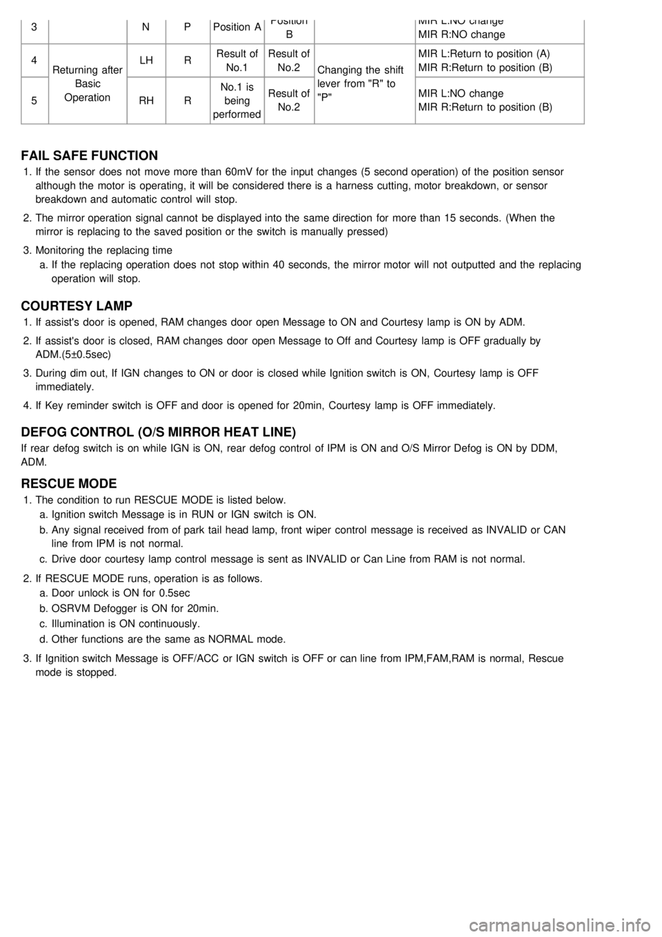
3NPPosition A Position
B MIR L:NO change
MIR R:NO change
4 Returning after
Basic
Operation LH
RResult of
No.1 Result of
No.2 Changing the shift
lever from "R" to
"P" MIR L:Return to position (A)
MIR R:Return to position (B)
5 RHRNo.1 is
being
performed Result of
No.2 MIR L:NO change
MIR R:Return to position (B)
FAIL SAFE FUNCTION
1.
If the sensor does not move more than 60mV for the input changes (5 second operation) of the position sensor
although the motor is operating, it will be considered there is a harness cutting, motor breakdown, or sensor
breakdown and automatic control will stop.
2. The mirror operation signal cannot be displayed into the same direction for more than 15 seconds. (When the
mirror is replacing to the saved position or the switch is manually pressed)
3. Monitoring the replacing time
a. If the replacing operation does not stop within 40 seconds, the mirror motor will not outputted and the replacing
operation will stop.
COURTESY LAMP
1.If assist's door is opened, RAM changes door open Message to ON and Courtesy lamp is ON by ADM.
2. If assist's door is closed, RAM changes door open Message to Off and Courtesy lamp is OFF gradually by
ADM.(5±0.5sec)
3. During dim out, If IGN changes to ON or door is closed while Ignition switch is ON, Courtesy lamp is OFF
immediately.
4. If Key reminder switch is OFF and door is opened for 20min, Courtesy lamp is OFF immediately.
DEFOG CONTROL (O/S MIRROR HEAT LINE)
If rear defog switch is on while IGN is ON, rear defog control of IPM is ON and O/S Mirror Defog is ON by DDM,
ADM.
RESCUE MODE
1.The condition to run RESCUE MODE is listed below.
a. Ignition switch Message is in RUN or IGN switch is ON.
b. Any signal received from of park tail head lamp, front wiper control message is received as INVALID or CAN
line from IPM is not normal.
c. Drive door courtesy lamp control message is sent as INVALID or Can Line from RAM is not normal.
2. If RESCUE MODE runs, operation is as follows.
a. Door unlock is ON for 0.5sec
b. OSRVM Defogger is ON for 20min.
c. Illumination is ON continuously.
d. Other functions are the same as NORMAL mode.
3. If Ignition switch Message is OFF/ACC or IGN switch is OFF or can line from IPM,FAM,RAM is normal, Rescue
mode is stopped.
Page 1573 of 1575

2007 > 2.7L V6 GASOLINE >
ADJUSTMENT PROCEDURE
IGNITION LOCK SWITCH
1. Disconnect 2P- connector from a ignition lock switch.
2. Disconnect the ignition lock switch. (if you can install a tester with the switch fixed, this step can be omissible)
3. Check for continuity between terminals. (refer to the table below)
Clutch pedal position Ignition lock switch Continuity
Released ReleasedNO
Pressed PressedYES
If there is difference between what tested and the table above, replace the ignition lock switch with a new one.
If not, install the ignition lock switch and adjust the clutch pedal.
TORQUE :
8~10Nm (80~100kgf.cm, 5.8~7.2lb- ft)
Clutch pedal and Ignition lock switch
a. Inspect a ignition lock switch.
b. Remove the driver's seat mat to adjust a clutch pedal.
c. No gap between a clutch master cylinder pistion and push rod can cause clutch slip.
1. Loosen and draw out the bolt until it is off the pedal surface.
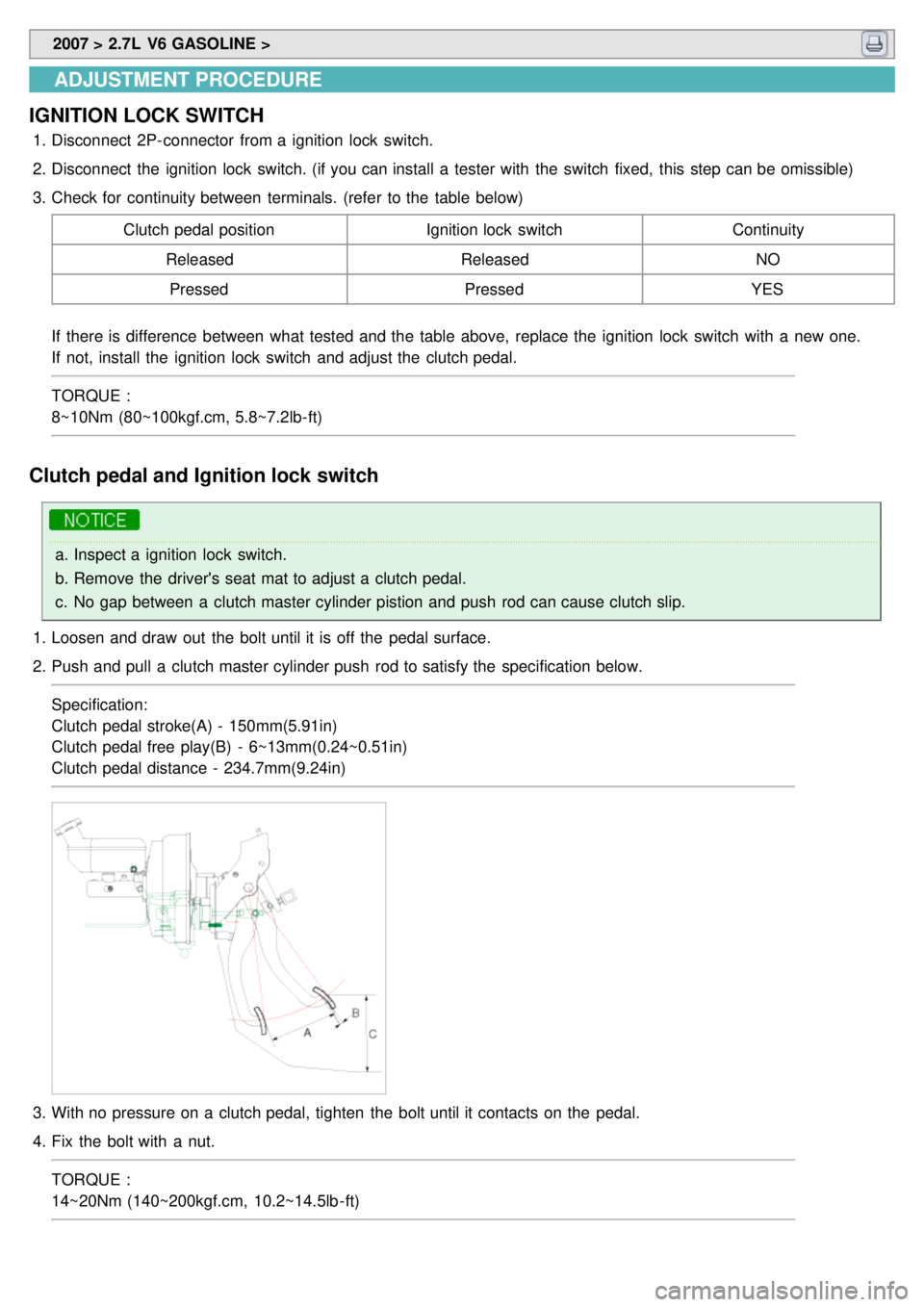
2. Push and pull a clutch master cylinder push rod to satisfy the specification below.
Specification:
Clutch pedal stroke(A) - 150mm(5.91in)
Clutch pedal free play(B) - 6~13mm(0.24~0.51in)
Clutch pedal distance - 234.7mm(9.24in)
3.With no pressure on a clutch pedal, tighten the bolt until it contacts on the pedal.
4. Fix the bolt with a nut.
TORQUE :
14~20Nm (140~200kgf.cm, 10.2~14.5lb - ft)
Page 1574 of 1575
5.Press the clutch pedal to the seat ground.
6. Adjust the ignition lock switch position with the pedal a little(23~26mm) raised.
7. Install the ignition lock switch firmly.
TORQUE:
8~10Nm (80~100kgf.cm, 5.8~7.2lb- ft)
REPLACEMENT
a.Inspect the continuity of the ignition lock switch.
b. Remove the floor mat before adjusting the clutch pedal.
1. Remove the ignition lock switch.
2. Remove the snap pin and the clevis pin(A) connecting the clutch master cylinder push rod and the clutch pedal.
3.Remove the clutch master cylinder mounting nut(A,B) and the clutch pedal mounting nut(C).
Page 1575 of 1575
4.Remove the clutch pedal.
5. Install a new one by tightening the bolts of the clutch pedal bracket and master cylinder .
TORQUE :
19~26 Nm(19~260 kgf.cm, 13.8~18.9 Ib- ft)(Clutch pedal bracket)
12~16 Nm(120~160 kgf.cm, 8.7~11.6 Ib- ft)(Clutch master cylinder)
6. Grease the clevis pin and insert it and the snap pin.
7. Adjust the clutch pedal and the ignition lock switch.