2007 KIA CARNIVAL ignition
[x] Cancel search: ignitionPage 1234 of 1575
CLOSE signal.
b. RAM will pass this signal to LH PSD and RH PSD then the burglar alarm state is decided depending on the
vehicle condition.
f. PTG open/close
a. Only with the information received by RKE, the burglar alarm system cannot distinguish the OPEN signal from
CLOSE signal.
b. RAM will pass this signal to PTG module then the burglar alarm state is decided depending on the vehicle
condition.
g. Panic by key fob
a. Whenever this signal is received, the PANIC function is activated (unless the system is already in an ALARM
state).
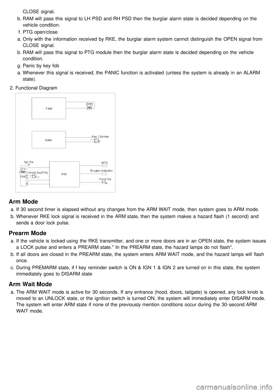
2. Functional Diagram
Arm Mode
a.If 30 second timer is elapsed without any changes from the ARM WAIT mode, then system goes to ARM mode.
b. Whenever RKE lock signal is received in the ARM state, then the system makes a hazard flash (1 second) and
sends a door lock pulse.
Prearm Mode
a.If the vehicle is locked using the RKE transmitter, and one or more doors are in an OPEN state, the system issues
a LOCK pulse and enters a PREARM state." In the PREARM state, the hazard lamps do not flash".
b. If all doors are closed in the PREARM state, the system enters ARM WAIT mode, and the hazard lamps will flash
once.
c. During PREMARM state, if f key reminder switch is ON & IGN 1 & IGN 2 are turned on in this state, the system
immediately goes to DISARM state
Arm Wait Mode
a.The ARM WAIT mode is active for 30 seconds. If any entrance (hood, doors, tailgate) is opened, any lock knob is
moved to an UNLOCK state, or the ignition switch is turned ON, the system will immediately enter DISARM mode.
The system will enter ARM state if none of the previously mention conditions occur during the 30- second ARM
WAIT mode.
Page 1241 of 1575
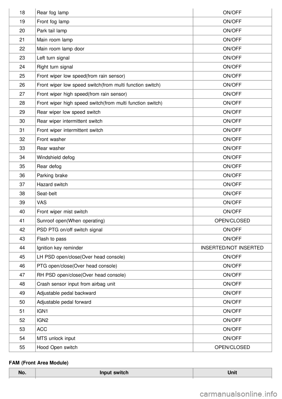
18Rear fog lamp ON/OFF
19 Front fog lamp ON/OFF
20 Park tail lamp ON/OFF
21 Main room lamp ON/OFF
22 Main room lamp door ON/OFF
23 Left turn signal ON/OFF
24 Right turn signal ON/OFF
25 Front wiper low speed(from rain sensor) ON/OFF
26 Front wiper low speed switch(from multi function switch) ON/OFF
27 Front wiper high speed(from rain sensor) ON/OFF
28 Front wiper high speed switch(from multi function switch) ON/OFF
29 Rear wiper low speed switch ON/OFF
30 Rear wiper intermittent switch ON/OFF
31 Front wiper intermittent switch ON/OFF
32 Front washer ON/OFF
33 Rear washer ON/OFF
34 Windshield defog ON/OFF
35 Rear defog ON/OFF
36 Parking brake ON/OFF
37 Hazard switch ON/OFF
38 Seat- belt ON/OFF
39 VAS ON/OFF
40 Front wiper mist switch ON/OFF
41 Sunroof open(When operating) OPEN/CLOSED
42 PSD PTG on/off switch signal ON/OFF
43 Flash to pass ON/OFF
44 Ignition key reminder INSERTED/NOT INSERTED
45 LH PSD open/close(Over head console) ON/OFF
46 PTG open/close(Over head console) ON/OFF
47 RH PSD open/close(Over head console) ON/OFF
48 Crash sensor input from airbag unit ON/OFF
49 Adjustable pedal backward ON/OFF
50 Adjustable pedal forward ON/OFF
51 IGN1 ON/OFF
52 IGN2 ON/OFF
53 ACC ON/OFF
54 MTS unlock input ON/OFF
55 Hood Open switch OPEN/CLOSED
FAM (Front Area Module) No. Input switch Unit
Page 1248 of 1575
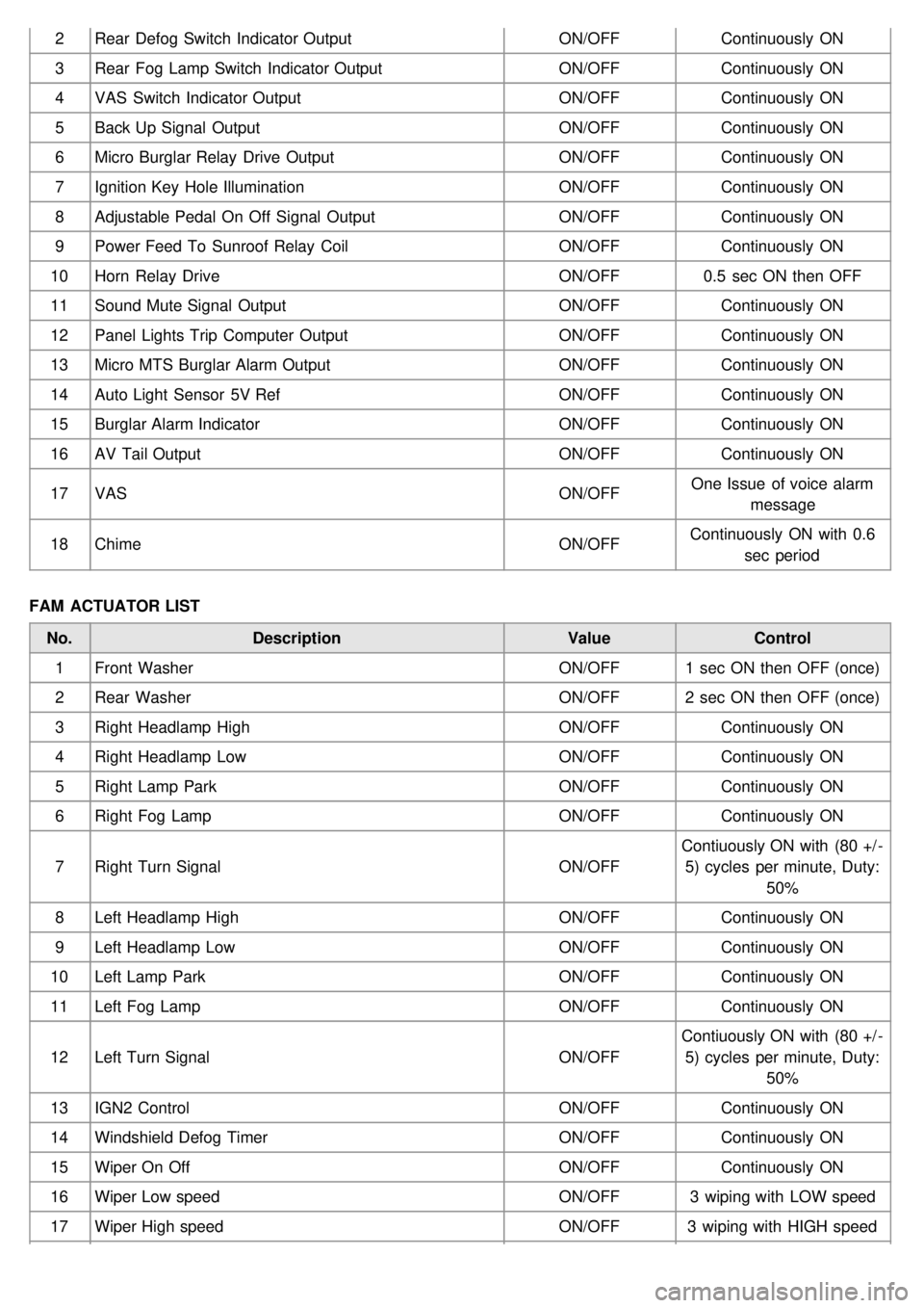
2Rear Defog Switch Indicator Output ON/OFFContinuously ON
3 Rear Fog Lamp Switch Indicator Output ON/OFFContinuously ON
4 VAS Switch Indicator Output ON/OFFContinuously ON
5 Back Up Signal Output ON/OFFContinuously ON
6 Micro Burglar Relay Drive Output ON/OFFContinuously ON
7 Ignition Key Hole Illumination ON/OFFContinuously ON
8 Adjustable Pedal On Off Signal Output ON/OFFContinuously ON
9 Power Feed To Sunroof Relay Coil ON/OFFContinuously ON
10 Horn Relay Drive ON/OFF0.5 sec ON then OFF
11 Sound Mute Signal Output ON/OFFContinuously ON
12 Panel Lights Trip Computer Output ON/OFFContinuously ON
13 Micro MTS Burglar Alarm Output ON/OFFContinuously ON
14 Auto Light Sensor 5V Ref ON/OFFContinuously ON
15 Burglar Alarm Indicator ON/OFFContinuously ON
16 AV Tail Output ON/OFFContinuously ON
17 VAS ON/OFFOne Issue of voice alarm
message
18 Chime ON/OFFContinuously ON with 0.6
sec period
FAM ACTUATOR LIST No. Description ValueControl
1 Front Washer ON/OFF1 sec ON then OFF (once)
2 Rear Washer ON/OFF2 sec ON then OFF (once)
3 Right Headlamp High ON/OFFContinuously ON
4 Right Headlamp Low ON/OFFContinuously ON
5 Right Lamp Park ON/OFFContinuously ON
6 Right Fog Lamp ON/OFFContinuously ON
7 Right Turn Signal ON/OFFContiuously ON with (80 +/ -
5) cycles per minute, Duty: 50%
8 Left Headlamp High ON/OFFContinuously ON
9 Left Headlamp Low ON/OFFContinuously ON
10 Left Lamp Park ON/OFFContinuously ON
11 Left Fog Lamp ON/OFFContinuously ON
12 Left Turn Signal ON/OFFContiuously ON with (80 +/ -
5) cycles per minute, Duty: 50%
13 IGN2 Control ON/OFFContinuously ON
14 Windshield Defog Timer ON/OFFContinuously ON
15 Wiper On Off ON/OFFContinuously ON
16 Wiper Low speed ON/OFF3 wiping with LOW speed
17 Wiper High speed ON/OFF3 wiping with HIGH speed
Page 1259 of 1575
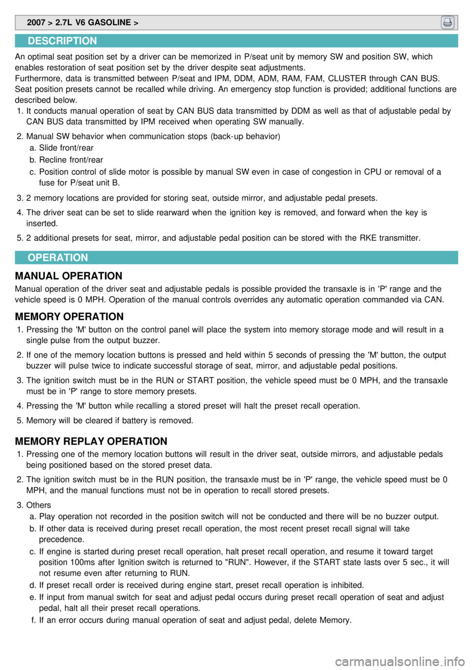
2007 > 2.7L V6 GASOLINE >
DESCRIPTION
An optimal seat position set by a driver can be memorized in P/seat unit by memory SW and position SW, which
enables restoration of seat position set by the driver despite seat adjustments.
Furthermore, data is transmitted between P/seat and IPM, DDM, ADM, RAM, FAM, CLUSTER through CAN BUS.
Seat position presets cannot be recalled while driving. An emergency stop function is provided; additional functions are
described below.
1. It conducts manual operation of seat by CAN BUS data transmitted by DDM as well as that of adjustable pedal by
CAN BUS data transmitted by IPM received when operating SW manually.
2. Manual SW behavior when communication stops (back- up behavior)
a. Slide front/rear
b. Recline front/rear
c. Position control of slide motor is possible by manual SW even in case of congestion in CPU or removal of a
fuse for P/seat unit B.
3. 2 memory locations are provided for storing seat, outside mirror, and adjustable pedal presets.
4. The driver seat can be set to slide rearward when the ignition key is removed, and forward when the key is
inserted.
5. 2 additional presets for seat, mirror, and adjustable pedal position can be stored with the RKE transmitter.
OPERATION
MANUAL OPERATION
Manual operation of the driver seat and adjustable pedals is possible provided the transaxle is in 'P' range and the
vehicle speed is 0 MPH. Operation of the manual controls overrides any automatic operation commanded via CAN.
MEMORY OPERATION
1. Pressing the 'M' button on the control panel will place the system into memory storage mode and will result in a
single pulse from the output buzzer.
2. If one of the memory location buttons is pressed and held within 5 seconds of pressing the 'M' button, the output
buzzer will pulse twice to indicate successful storage of seat, mirror, and adjustable pedal positions.
3. The ignition switch must be in the RUN or START position, the vehicle speed must be 0 MPH, and the transaxle
must be in 'P' range to store memory presets.
4. Pressing the 'M' button while recalling a stored preset will halt the preset recall operation.
5. Memory will be cleared if battery is removed.
MEMORY REPLAY OPERATION
1.Pressing one of the memory location buttons will result in the driver seat, outside mirrors, and adjustable pedals
being positioned based on the stored preset data.
2. The ignition switch must be in the RUN position, the transaxle must be in 'P' range, the vehicle speed must be 0
MPH, and the manual functions must not be in operation to recall stored presets.
3. Others
a. Play operation not recorded in the position switch will not be conducted and there will be no buzzer output.
b. If other data is received during preset recall operation, the most recent preset recall signal will take
precedence.
c. If engine is started during preset recall operation, halt preset recall operation, and resume it toward target
position 100ms after Ignition switch is returned to "RUN". However, if the START state lasts over 5 sec., it will
not resume even after returning to RUN.
d. If preset recall order is received during engine start, preset recall operation is inhibited.
e. If input from manual switch for seat and adjust pedal occurs during preset recall operation of seat and adjust
pedal, halt all their preset recall operations.
f. If an error occurs during manual operation of seat and adjust pedal, delete Memory.
Page 1310 of 1575
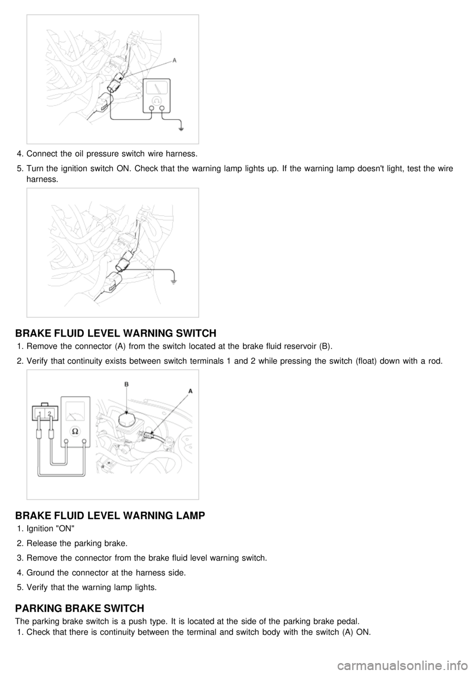
4.Connect the oil pressure switch wire harness.
5. Turn the ignition switch ON. Check that the warning lamp lights up. If the warning lamp doesn't light, test the wire
harness.
BRAKE FLUID LEVEL WARNING SWITCH
1.Remove the connector (A) from the switch located at the brake fluid reservoir (B).
2. Verify that continuity exists between switch terminals 1 and 2 while pressing the switch (float) down with a rod.
BRAKE FLUID LEVEL WARNING LAMP
1.Ignition "ON"
2. Release the parking brake.
3. Remove the connector from the brake fluid level warning switch.
4. Ground the connector at the harness side.
5. Verify that the warning lamp lights.
PARKING BRAKE SWITCH
The parking brake switch is a push type. It is located at the side of the parking brake pedal.
1. Check that there is continuity between the terminal and switch body with the switch (A) ON.
Page 1312 of 1575
SEAT BELT WARNING LAMP
With the ignition switch turned ON, verify that the lamp glows.Seat belt condition Warning lamp
Fastened OFF
Not fastened ON
Page 1328 of 1575
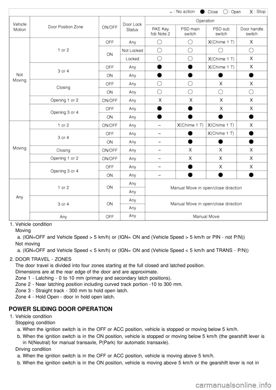
1.Vehicle condition
Moving
a. (IGN=OFF and Vehicle Speed > 5 km/h) or (IGN= ON and (Vehicle Speed > 5 km/h or PIN - not P/N))
Not moving a. (IGN=OFF and Vehicle Speed < 5 km/h) or (IGN= ON and (Vehicle Speed < 5 km/h and TRANS - P/N))
2. DOOR TRAVEL - ZONES
The door travel is divided into four zones starting at the full closed and latched position.
Dimensions are at the rear edge of the door and are approximate.
Zone 1 - Latching - 0 to 10 mm (primary and secondary latch positions).
Zone 2 - Near latching position including curved track portion - 10 to 300 mm.
Zone 3 - Straight track - 300 mm to hold open latch.
Zone 4 - Hold Open - door in hold open latch.
POWER SLIDING DOOR OPERATION
1.Vehicle condition
Stopping condition
a. When the ignition switch is in the OFF or ACC position, vehicle is stopped or moving below 5 km/h.
b. When the ignition switch is in the ON position, vehicle is stopped or moving below 5 km/h (the gearshift lever is
in N(Neutral) for manual transaxle, P(Park) for automatic transaxle).
Driving condition a. When the ignition switch is in the OFF or ACC position, vehicle is moving above 5 km/h.
b. When the ignition switch is in the ON position, vehicle is moving above 5 km/h or the gearshift lever is not in
N(Neutral) for manual transaxle, P(Park) for automatic transaxle.
Page 1334 of 1575
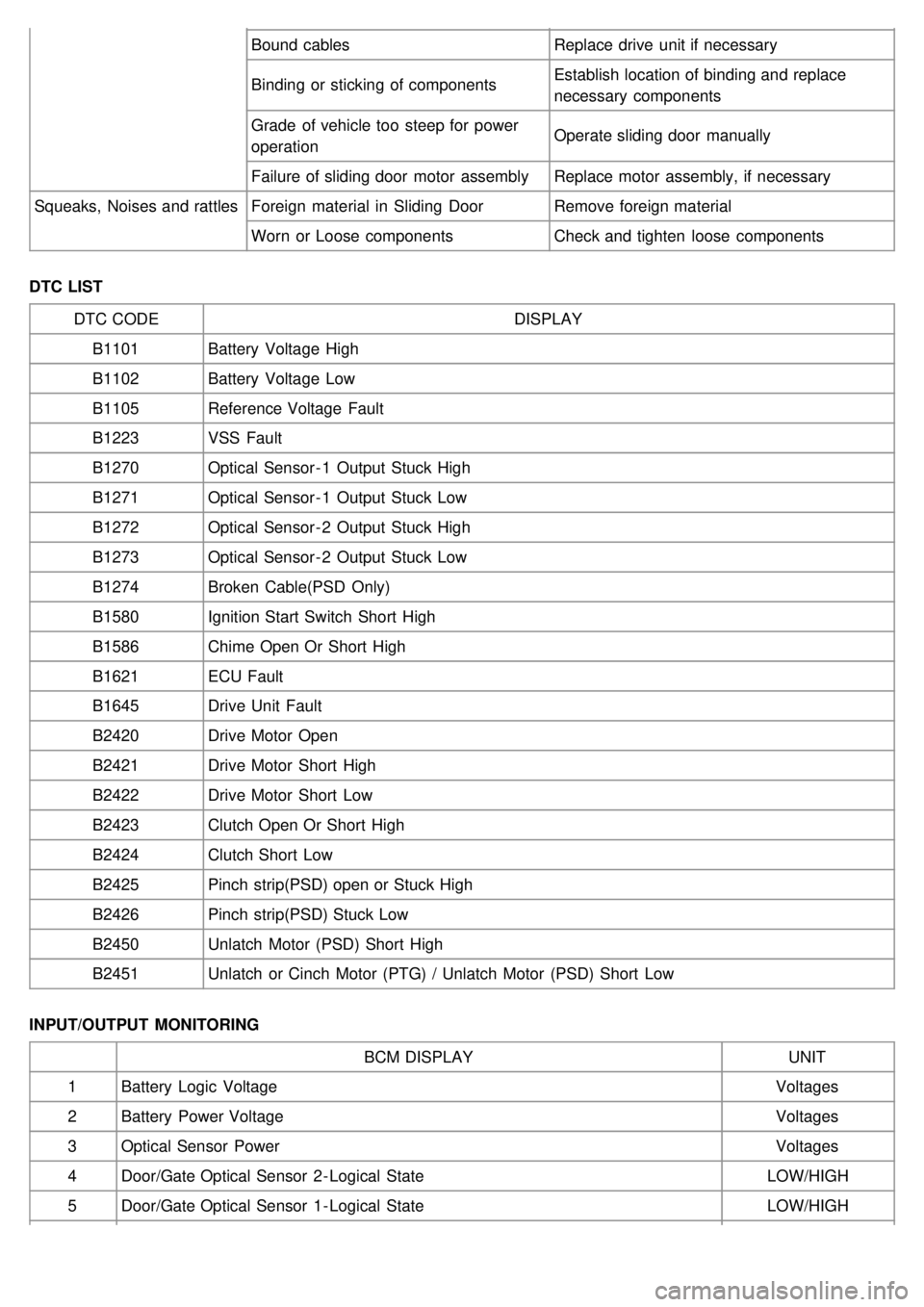
Bound cablesReplace drive unit if necessary
Binding or sticking of components Establish location of binding and replace
necessary components
Grade of vehicle too steep for power
operation Operate sliding door manually
Failure of sliding door motor assembly Replace motor assembly, if necessary
Squeaks, Noises and rattles Foreign material in Sliding Door Remove foreign material
Worn or Loose components Check and tighten loose components
DTC LIST DTC CODE DISPLAY
B1101 Battery Voltage High
B1102 Battery Voltage Low
B1105 Reference Voltage Fault
B1223 VSS Fault
B1270 Optical Sensor - 1 Output Stuck High
B1271 Optical Sensor - 1 Output Stuck Low
B1272 Optical Sensor - 2 Output Stuck High
B1273 Optical Sensor - 2 Output Stuck Low
B1274 Broken Cable(PSD Only)
B1580 Ignition Start Switch Short High
B1586 Chime Open Or Short High
B1621 ECU Fault
B1645 Drive Unit Fault
B2420 Drive Motor Open
B2421 Drive Motor Short High
B2422 Drive Motor Short Low
B2423 Clutch Open Or Short High
B2424 Clutch Short Low
B2425 Pinch strip(PSD) open or Stuck High
B2426 Pinch strip(PSD) Stuck Low
B2450 Unlatch Motor (PSD) Short High
B2451 Unlatch or Cinch Motor (PTG) / Unlatch Motor (PSD) Short Low
INPUT/OUTPUT MONITORING BCM DISPLAY UNIT
1 Battery Logic Voltage Voltages
2 Battery Power Voltage Voltages
3 Optical Sensor Power Voltages
4 Door/Gate Optical Sensor 2 - Logical State LOW/HIGH
5 Door/Gate Optical Sensor 1 - Logical State LOW/HIGH