2007 KIA CARNIVAL stop start
[x] Cancel search: stop startPage 729 of 1575

3.The two coolant temperature sensors are installed to the heater inner. The sensor valves determine heater
operation.
4. One of the temperature sensors functions to prevent the heater from overheating.
If the sensor temperature valve exceeds 125°C, the fuel will be cut and the heater will be deactivated by the
determination of the overheating of the heater.
The other temperature sensor determines the operation mode of the fuel fired heater.The temperature of this
sensor enables to activate the heater at full load(5kw) or half load(2.5kw).
• The coolant temperature shown on the above Figure is the value of the inner sensor and the actual coolant
temperature is higher about 5°C ~7°C than the above value.
OPERATION
Switch on/ Operation start
The fuel fired heater is operated when the coolant temperature is below 68°C and the ambient temperature is below
2°C after starting the engine.
At this time, the glow plug and combustion air fan are operated first and after 30 seconds, the dosing pump is
operated with stopping the combustion fan for 3 seconds.
After that, the operation of the fan increases continuously until it approaches to full load within 56 seconds. If fuel
supply reaches to full load the glow plug does not operate and the operation of the fan reaches to full load.
After that the glow plug monitors ignition condition as a flame sensor for 45 seconds.
The above operation procedure is done automatically and in case the ignition fails, the above operation will be done
again automatically.
If the condition of ignition failure sustains continuously, fuel supply and fan operation will be stopped and error codes
will be stored to find cause of failure.
Generally, the cause of ignition failure during combustion is caused by the automatic re- operation of the above
procedure.
Operation for heating
The fuel fired heater operates at full load when the coolant temperature is below 68°C and the ambient temperature is
below 2°C after starting the engine.
It operates at half load when the coolant temperature is 74°C and it operates at idle mode when the coolant
temperature is 78°C.
The fuel fired heater during the transformation process does a cleaning function from the half mode to the idle mode.
At idle mode, all components do not work.
The fuel fired heater operating at idle mode turns into the half load when the coolant temperature is 74°C. At this time,
if the coolant temperature drops again below 68°C, the heater operates with full load and turns into the idle mode if
the temperature is 78°C.
This serial operating process is performed automatically.
Key switch off / Operation stop
The fuel fired heater ECU stops the operation of the fuel pump and cuts fuel supply when shutting off the engine
during the heater operation.
The heater conducts cleaning operation at this time.
This is a process of burning the fuel completely supplied in the heater inner.
In this process, the glow plug and combustion air fan are operated.
Page 731 of 1575

2007 > 2.7L V6 GASOLINE >
INSPECTION
OPERATION TEST
Fuel-fired heater operation test by force using Hi-Scan
1. Start the engine.
2. Connect the Hi - Scan to the vehicle.
3. Select "SORENTO" and then select "FUEL FIRED HEATER".
4. Select "04. ACTUATION TEST" mode.
5. Select "PREFILLING + HEATING" to conduct the performance test after replacing the fuel fired heater system.
Fuel supply and heating will be initiated if the "F1 key STRT" is pressed.
However, a repair or replacement of the components related to the fuel line system in the fuel- fired heater were not
done, operate the component by force after selecting the appropriate item from the menu screen.
Do not operate the system by force with selecting the “ PREFILLING + HEATING ” option if no repair for the
fuel line relating components has been done.
This means the fuel is in the fuel line.If an excessive fuel is supplied, it may cause smoke and abnormal
"Banging" noise when the fuel is burned.
If the "F2 KEY STOP" is pressed, operation test is stopped.
For self - diagnosis test and sensors outputs during compulsory operation test, press "ESC KEY".
When a self - diagnosis test is completed, disconnect the self - diagnosis connector or press "F2 KEY STOP"
from the "PREFILLING + HEATING" menu to stop the compulsory operation.
In case of selecting the individual part (ex. Combustion air fan, water pump, ), press "ESC KEY" to stop the
test.
In case of selecting the "PREFILLING + HEATING" option, about 2 minutes are required to conduct cleaning
process after pressing the "F2 KEY STOP".
It is a normal process to burn the fuel left in the fuel line.
6. To conduct self diagnosis test, press "ESC" and then "01. DIAGNOSTIC TROUBLE CODES" option.
7.Select "02. CURRENT DATA" to view the current status of the components.
Page 870 of 1575

2.With the engine stopped, step on the brake pedal several times.
Then step on the brake pedal and start the engine. If the pedal moves downward slightly, the booster is in good
condition. If there is no change, the booster is inoperative.
3.With the engine running, step on the brake pedal and then stop the engine.
Hold the pedal depressed for 30 seconds. If the pedal height does not change, the booster is in good condition, if
the pedal rises, the booster is inoperative.
If the above three tests are okay, the booster performance can be determined as good.
Even if one of the above three tests is not okay, check the check valve, vacuum hose and booster for malfunction.
VACUUM HOSE (CHECK VALVE)
INSPECTION
1. Disconnect the brake booster vacuum hose (check valve built in) (A) at the booster (B).
2. Start the engine and let it idle. There should be vacuum available. If no vacuum is available, the check valve is not
working properly. Replace the back booster vacuum hose and check valve and retest.
[LHD]
Page 937 of 1575

c.Stop lamp switch circuit.
d. Check the hydraulic circuit for leakage.
Communication with Scan tool is not possible.
(Communication with any system is not possible) a.
Power source circuit
b. Diagnosis line
Communication with Scan tool is not possible.
(Communication with ABS only is not possible) a.
Power source circuit
b. Diagnosis line
c. HECU
When ignition key is turned ON (engine OFF), the ABS
warning lamp does not light up. a.
ABS warning lamp circuit
b. HECU
Even after the engine is started, the ABS warning lamp
remains ON. a.
ABS warning lamp circuit
b. HECU
During ABS operation, the brake pedal may vibrate or may not be able to be depressed. Such phenomena are
due to intermittent changes in hydraulic pressure inside the brake line to prevent the wheels from locking and is
not an abnormality.
DETECTING CONDITION
Trouble Symptoms Possible Cause
Brake operation varies depending on driving conditions and road
surface conditions, so diagnosis can be difficult.However if a normal
DTC is displayed, check the following probable cause. When the
problem is still occurring, replace the ABS control module. a.
Inoperative power source circuit
b. Inoperative wheel speed sensor circuit
c. Inoperative hydraulic circuit for leakage
d. Inoperative HECU
INSPECTION PROCEDURES
DTC INSPECTION
1. Connect the Scan Tool with the data link connector and turn the ignition switch ON.
2. Verify that the system is operating to specifications.
Is the system operating to specifications ?
▶ Check the power source circuit.
▶ Erase the DTC and recheck using Scan Tool.
CHECK THE POWER SOURCE CIRCUIT.
1. Disconnect the connector from the ABS control module.
2. Turn the ignition switch ON, measure the voltage between terminal 18 of the ABS control module harness side
connector and body ground.
Specification: approximately B+
Is the voltage within specification?
▶ Check the ground circuit.
▶ Check the harness or connector between the fuse (10A) in the engine compartment junction block and the ABS
control module. Repair if necessary.
Page 1214 of 1575

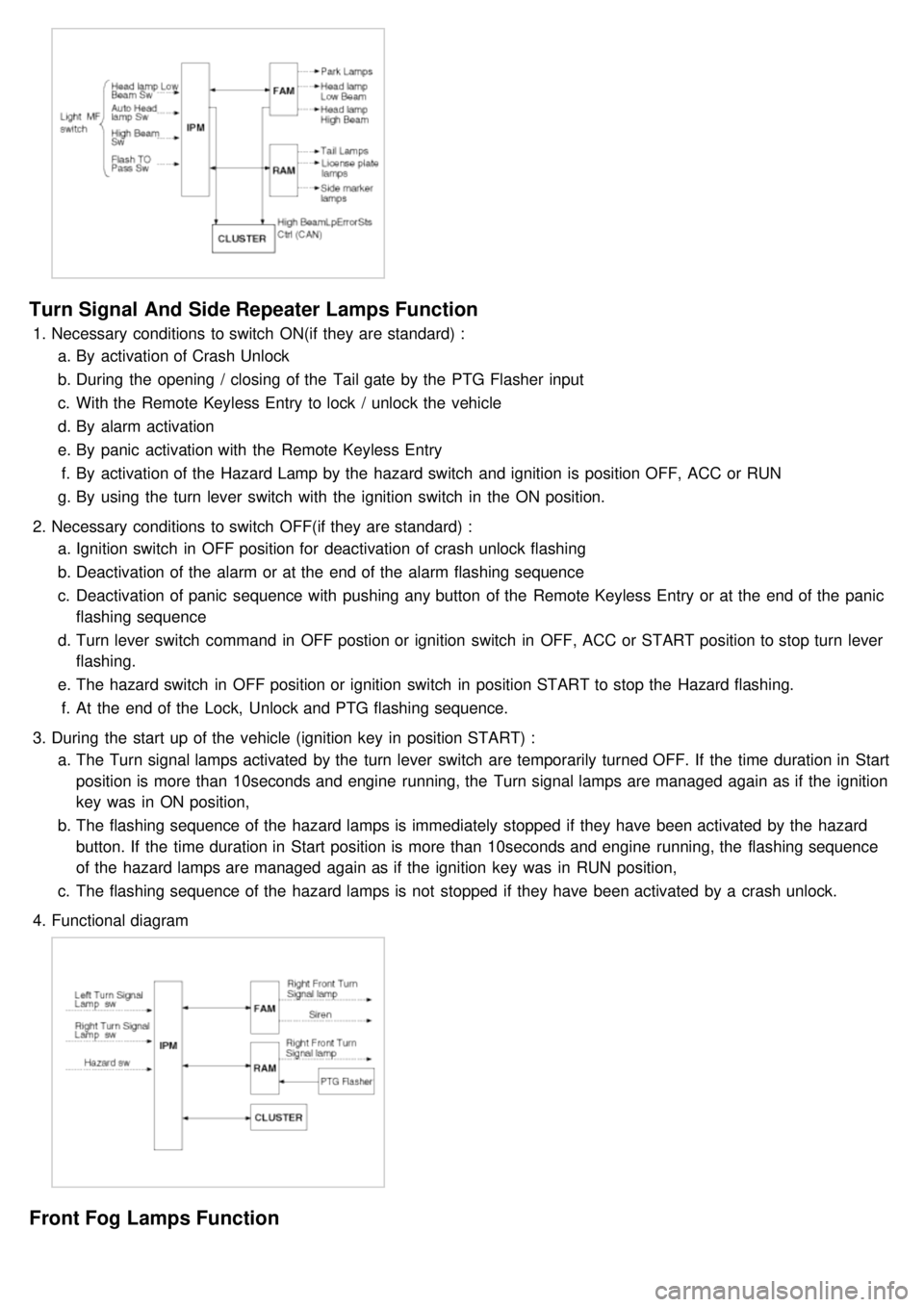
Turn Signal And Side Repeater Lamps Function
1.Necessary conditions to switch ON(if they are standard) :
a. By activation of Crash Unlock
b. During the opening / closing of the Tail gate by the PTG Flasher input
c. With the Remote Keyless Entry to lock / unlock the vehicle
d. By alarm activation
e. By panic activation with the Remote Keyless Entry
f. By activation of the Hazard Lamp by the hazard switch and ignition is position OFF, ACC or RUN
g. By using the turn lever switch with the ignition switch in the ON position.
2. Necessary conditions to switch OFF(if they are standard) :
a. Ignition switch in OFF position for deactivation of crash unlock flashing
b. Deactivation of the alarm or at the end of the alarm flashing sequence
c. Deactivation of panic sequence with pushing any button of the Remote Keyless Entry or at the end of the panic
flashing sequence
d. Turn lever switch command in OFF postion or ignition switch in OFF, ACC or START position to stop turn lever
flashing.
e. The hazard switch in OFF position or ignition switch in position START to stop the Hazard flashing.
f. At the end of the Lock, Unlock and PTG flashing sequence.
3. During the start up of the vehicle (ignition key in position START) :
a. The Turn signal lamps activated by the turn lever switch are temporarily turned OFF. If the time duration in Start
position is more than 10seconds and engine running, the Turn signal lamps are managed again as if the ignition
key was in ON position,
b. The flashing sequence of the hazard lamps is immediately stopped if they have been activated by the hazard
button. If the time duration in Start position is more than 10seconds and engine running, the flashing sequence
of the hazard lamps are managed again as if the ignition key was in RUN position,
c. The flashing sequence of the hazard lamps is not stopped if they have been activated by a crash unlock.
4. Functional diagram
Front Fog Lamps Function
Page 1216 of 1575

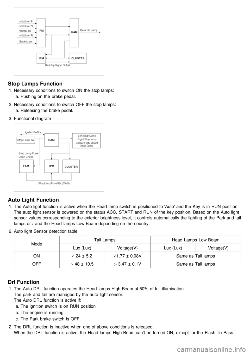
Stop Lamps Function
1.Necessary conditions to switch ON the stop lamps:
a. Pushing on the brake pedal.
2. Necessary conditions to switch OFF the stop lamps:
a. Releasing the brake pedal.
3. Functional diagram
Auto Light Function
1.The Auto light function is active when the Head lamp switch is positioned to 'Auto' and the Key is in RUN position.
The auto light sensor is powered on the status ACC, START and RUN of the key position. Based on the Auto light
sensor values corresponding to the exterior brightness level, it controls automatically the lighting of the Park and tail
lamps or / and the Head lamps Low Beam depending on the country.
2. Auto light Sensor detection table
Mode Tail Lamps
Head Lamps Low Beam
Lux (Lux) Voltage(V) Lux (Lux)Voltage(V)
ON < 24 ± 5.2 <1.77 ± 0.08V Same as Tail lamps
OFF > 48 ± 10.5 > 3.47 ± 0.1V Same as Tail lamps
Drl Function
1.The Auto DRL function operates the Head lamps High Beam at 50% of full illumination.
The park and tail are managed by the auto light sensor.
The Auto DRL function is active if:
a. The ignition switch is on RUN position
b. The engine is running.
c. The Park brake switch is OFF.
2. The DRL function is inactive when one of above conditions is released.
When the DRL function is active, the Head lamps High Beam can't be turned ON, except for the Flash To Pass
activation.
Page 1222 of 1575

Dimmable Backlighting
1.Working Conditions
The Dimmable backlighting is directly managed by the rheostat.
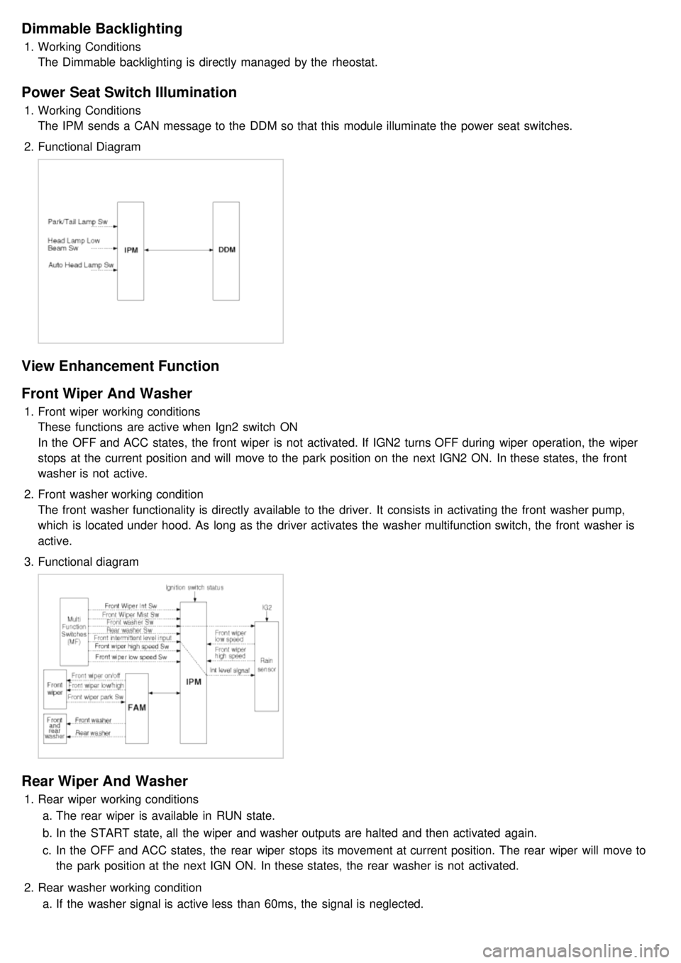
Power Seat Switch Illumination
1.Working Conditions
The IPM sends a CAN message to the DDM so that this module illuminate the power seat switches.
2. Functional Diagram
View Enhancement Function
Front Wiper And Washer
1.Front wiper working conditions
These functions are active when Ign2 switch ON
In the OFF and ACC states, the front wiper is not activated. If IGN2 turns OFF during wiper operation, the wiper
stops at the current position and will move to the park position on the next IGN2 ON. In these states, the front
washer is not active.
2. Front washer working condition
The front washer functionality is directly available to the driver. It consists in activating the front washer pump,
which is located under hood. As long as the driver activates the washer multifunction switch, the front washer is
active.
3. Functional diagram
Rear Wiper And Washer
1.Rear wiper working conditions
a. The rear wiper is available in RUN state.
b. In the START state, all the wiper and washer outputs are halted and then activated again.
c. In the OFF and ACC states, the rear wiper stops its movement at current position. The rear wiper will move to
the park position at the next IGN ON. In these states, the rear washer is not activated.
2. Rear washer working condition
a. If the washer signal is active less than 60ms, the signal is neglected.
Page 1223 of 1575

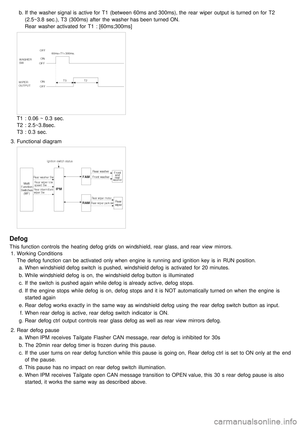
b.If the washer signal is active for T1 (between 60ms and 300ms), the rear wiper output is turned on for T2
(2.5~3.8 sec.), T3 (300ms) after the washer has been turned ON.
Rear washer activated for T1 : [60ms;300ms]
T1 : 0.06 ~ 0.3 sec.
T2 : 2.5~3.8sec.
T3 : 0.3 sec.
3. Functional diagram
Defog
This function controls the heating defog grids on windshield, rear glass, and rear view mirrors.
1. Working Conditions
The defog function can be activated only when engine is running and ignition key is in RUN position.
a. When windshield defog switch is pushed, windshield defog is activated for 20 minutes.
b. While windshield defog is on, the windshield defog button is illuminated
c. If the switch is pushed again while defog is already active, defog stops.
d. If the engine stops while defog is on, defog stops and it is NOT automatically turned on when the engine is
started again
e. Rear defog works exactly in the same way as windshield defog using the rear defog switch button as input.
f. When rear defog is active, rear defog switch indicator is ON.
g. Rear defog ctrl output controls rear glass defog as well as rear view mirrors defog.
2. Rear defog pause
a. When IPM receives Tailgate Flasher CAN message, rear defog is inhibited for 30s
b. The 20min rear defog timer is frozen during this pause.
c. If the user turns on rear defog function while this pause is going on, Rear defog ctrl is set to ON only at the end
of the pause.
d. This pause has no impact on rear defog switch illumination.
e. When IPM receives Tailgate open CAN message transition to OPEN value, this 30 s rear defog pause is also
started, it works the same way as described above.