2007 KIA CARNIVAL stop start
[x] Cancel search: stop startPage 1232 of 1575
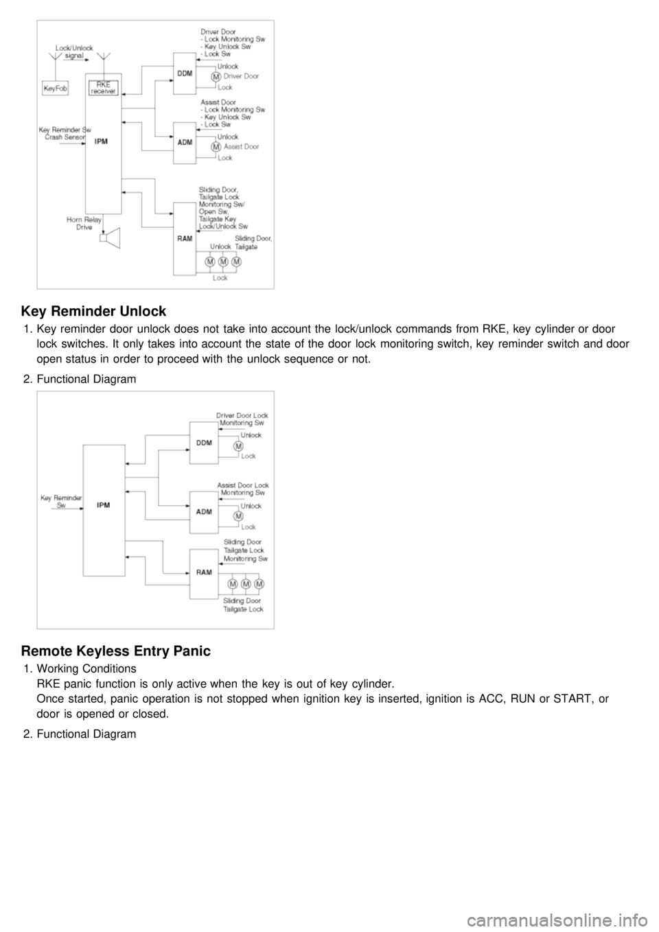
Key Reminder Unlock
1.Key reminder door unlock does not take into account the lock/unlock commands from RKE, key cylinder or door
lock switches. It only takes into account the state of the door lock monitoring switch, key reminder switch and door
open status in order to proceed with the unlock sequence or not.
2. Functional Diagram
Remote Keyless Entry Panic
1.Working Conditions
RKE panic function is only active when the key is out of key cylinder.
Once started, panic operation is not stopped when ignition key is inserted, ignition is ACC, RUN or START, or
door is opened or closed.
2. Functional Diagram
Page 1235 of 1575
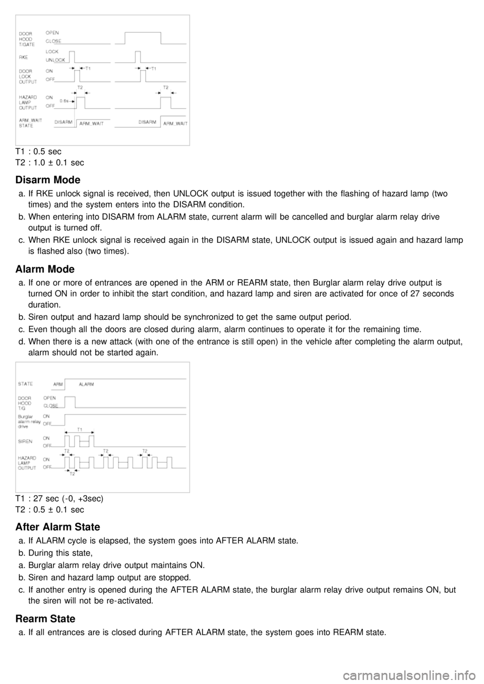
T1 : 0.5 sec
T2 : 1.0 ± 0.1 sec
Disarm Mode
a.If RKE unlock signal is received, then UNLOCK output is issued together with the flashing of hazard lamp (two
times) and the system enters into the DISARM condition.
b. When entering into DISARM from ALARM state, current alarm will be cancelled and burglar alarm relay drive
output is turned off.
c. When RKE unlock signal is received again in the DISARM state, UNLOCK output is issued again and hazard lamp
is flashed also (two times).
Alarm Mode
a.If one or more of entrances are opened in the ARM or REARM state, then Burglar alarm relay drive output is
turned ON in order to inhibit the start condition, and hazard lamp and siren are activated for once of 27 seconds
duration.
b. Siren output and hazard lamp should be synchronized to get the same output period.
c. Even though all the doors are closed during alarm, alarm continues to operate it for the remaining time.
d. When there is a new attack (with one of the entrance is still open) in the vehicle after completing the alarm output,
alarm should not be started again.
T1 : 27 sec ( - 0, +3sec)
T2 : 0.5 ± 0.1 sec
After Alarm State
a.If ALARM cycle is elapsed, the system goes into AFTER ALARM state.
b. During this state,
a. Burglar alarm relay drive output maintains ON.
b. Siren and hazard lamp output are stopped.
c. If another entry is opened during the AFTER ALARM state, the burglar alarm relay drive output remains ON, but
the siren will not be re- activated.
Rearm State
a.If all entrances are is closed during AFTER ALARM state, the system goes into REARM state.
Page 1259 of 1575
2007 > 2.7L V6 GASOLINE >
DESCRIPTION
An optimal seat position set by a driver can be memorized in P/seat unit by memory SW and position SW, which
enables restoration of seat position set by the driver despite seat adjustments.
Furthermore, data is transmitted between P/seat and IPM, DDM, ADM, RAM, FAM, CLUSTER through CAN BUS.
Seat position presets cannot be recalled while driving. An emergency stop function is provided; additional functions are
described below.
1. It conducts manual operation of seat by CAN BUS data transmitted by DDM as well as that of adjustable pedal by
CAN BUS data transmitted by IPM received when operating SW manually.
2. Manual SW behavior when communication stops (back- up behavior)
a. Slide front/rear
b. Recline front/rear
c. Position control of slide motor is possible by manual SW even in case of congestion in CPU or removal of a
fuse for P/seat unit B.
3. 2 memory locations are provided for storing seat, outside mirror, and adjustable pedal presets.
4. The driver seat can be set to slide rearward when the ignition key is removed, and forward when the key is
inserted.
5. 2 additional presets for seat, mirror, and adjustable pedal position can be stored with the RKE transmitter.
OPERATION
MANUAL OPERATION
Manual operation of the driver seat and adjustable pedals is possible provided the transaxle is in 'P' range and the
vehicle speed is 0 MPH. Operation of the manual controls overrides any automatic operation commanded via CAN.
MEMORY OPERATION
1. Pressing the 'M' button on the control panel will place the system into memory storage mode and will result in a
single pulse from the output buzzer.
2. If one of the memory location buttons is pressed and held within 5 seconds of pressing the 'M' button, the output
buzzer will pulse twice to indicate successful storage of seat, mirror, and adjustable pedal positions.
3. The ignition switch must be in the RUN or START position, the vehicle speed must be 0 MPH, and the transaxle
must be in 'P' range to store memory presets.
4. Pressing the 'M' button while recalling a stored preset will halt the preset recall operation.
5. Memory will be cleared if battery is removed.
MEMORY REPLAY OPERATION
1.Pressing one of the memory location buttons will result in the driver seat, outside mirrors, and adjustable pedals
being positioned based on the stored preset data.
2. The ignition switch must be in the RUN position, the transaxle must be in 'P' range, the vehicle speed must be 0
MPH, and the manual functions must not be in operation to recall stored presets.
3. Others
a. Play operation not recorded in the position switch will not be conducted and there will be no buzzer output.
b. If other data is received during preset recall operation, the most recent preset recall signal will take
precedence.
c. If engine is started during preset recall operation, halt preset recall operation, and resume it toward target
position 100ms after Ignition switch is returned to "RUN". However, if the START state lasts over 5 sec., it will
not resume even after returning to RUN.
d. If preset recall order is received during engine start, preset recall operation is inhibited.
e. If input from manual switch for seat and adjust pedal occurs during preset recall operation of seat and adjust
pedal, halt all their preset recall operations.
f. If an error occurs during manual operation of seat and adjust pedal, delete Memory.
Page 1260 of 1575
4.Operation control
a. Prioritization of operations
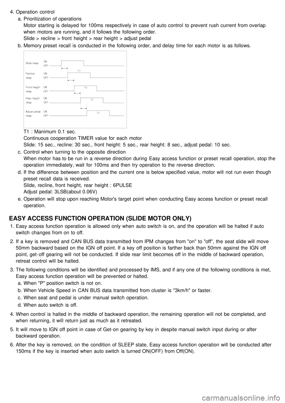
Motor starting is delayed for 100ms respectively in case of auto control to prevent rush current from overlap
when motors are running, and it follows the following order.
Slide > recline > front height > rear height > adjust pedal
b. Memory preset recall is conducted in the following order, and delay time for each motor is as follows.
T1 : Manimum 0.1 sec.
Continuous cooperation TIMER value for each motor
Slide: 15 sec., recline: 30 sec., front height: 5 sec., rear height: 8 sec., adjust pedal: 10 sec.
c. Control when turning to the opposite direction
When motor has to be run in a reverse direction during Easy access function or preset recall operation, stop the
operation immediately, wait for 100ms and then try operation to the reverse direction.
d. If the difference between position and the current one is below specified value, motor will not run even though
preset recall data is received.
Slide, recline, front height, rear height : 6PULSE
Adjust pedal: 3LSB(about 0.06V)
e. Operation will stop upon reaching Motor's target point when conducting Easy access function or preset recall
operation.
EASY ACCESS FUNCTION OPERATION (SLIDE MOTOR ONLY)
1.Easy access function operation is allowed only when auto switch is on, and the operation will be halted if auto
switch changes from on to off.
2. If a key is removed and CAN BUS data transmitted from IPM changes from "on" to "off", the seat slide will move
50mm backward based on the IGN off point. If a key off position is farther back than 50mm against the IGN off
point, get - off gearing will not be conducted. If slide rear limit becomes off in the middle of backward operation,
retreat control will be halted.
3. The following conditions will be identified and processed by IMS, and if any one of the following conditions is met,
Easy access function operation will be prevented or halted.
a. When "P" position switch is not on.
b. When Vehicle Speed in CAN BUS data transmitted from cluster is "3km/h" or faster.
c. When seat and pedal is under manual switch operation.
d. When auto switch is off.
4. When control is halted in the middle of backward operation, the remaining operation will not be completed, and
when returning, it will return just as much as it retreated.
5. It will move to IGN off point in case of Get- on gearing by key in despite manual switch input during or after
backward operation.
6. After the key is removed, on the condition of SLEEP state, Easy access function operation will be conducted after
150ms if the key is inserted when auto switch is turned ON(OFF) from Off(ON).
Page 1323 of 1575
2007 > 2.7L V6 GASOLINE >
DESCRIPTION
Power Sliding Door is an electro - mechanical system designed to provide power opening and closing of a vehicle's
sliding door through the push of a button of the transmitter key or the main control buttons on the overhead console
or the sub control buttons on the center pillar trim or inside/outside door handle switch.
The power sliding door will reverse direction of travel if resistance to movement is detected while the door is being
closed. If resistance to movement is detected while the power sliding door is being opened, the door will stop moving.
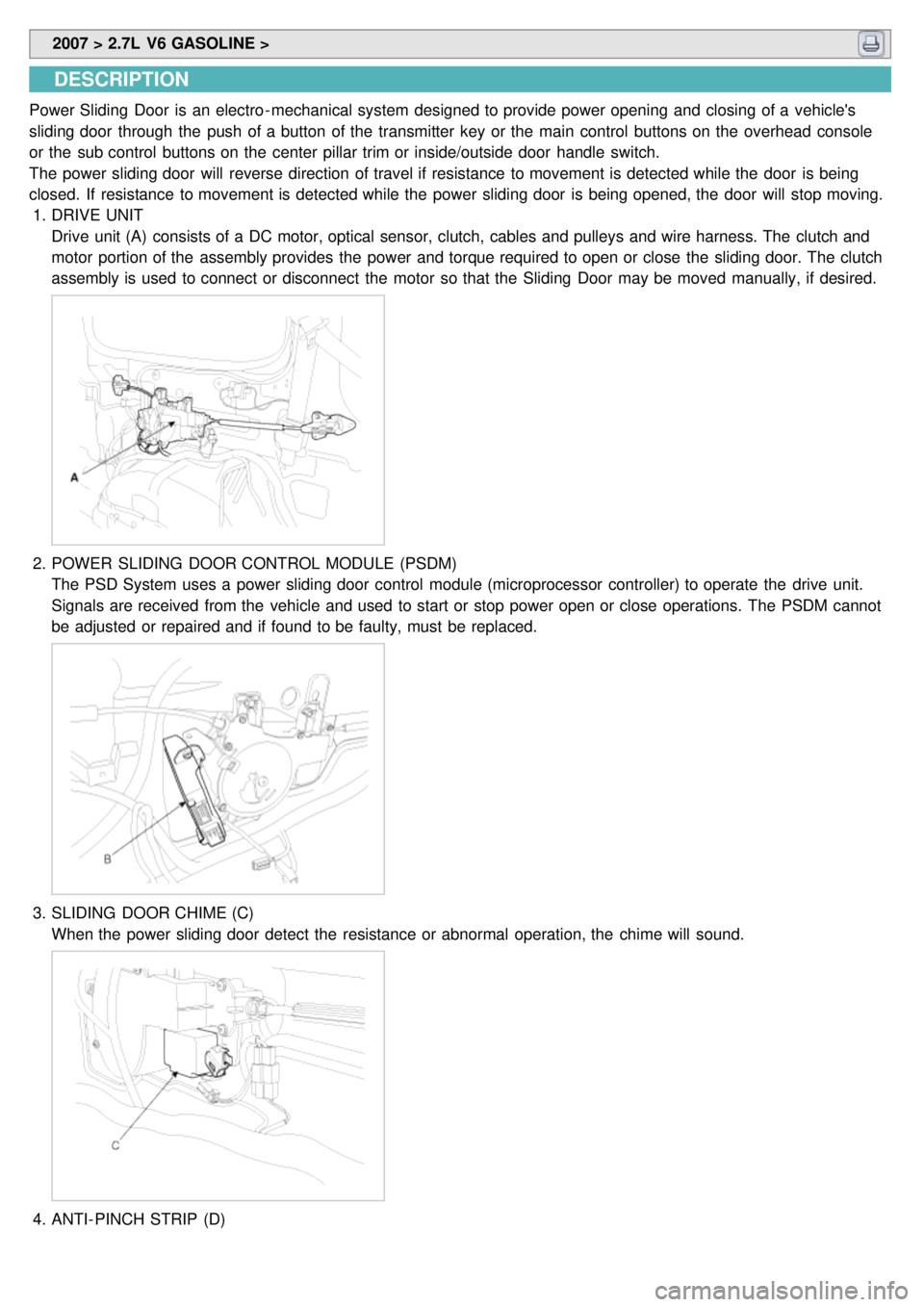
1. DRIVE UNIT
Drive unit (A) consists of a DC motor, optical sensor, clutch, cables and pulleys and wire harness. The clutch and
motor portion of the assembly provides the power and torque required to open or close the sliding door. The clutch
assembly is used to connect or disconnect the motor so that the Sliding Door may be moved manually, if desired.
2.POWER SLIDING DOOR CONTROL MODULE (PSDM)
The PSD System uses a power sliding door control module (microprocessor controller) to operate the drive unit.
Signals are received from the vehicle and used to start or stop power open or close operations. The PSDM cannot
be adjusted or repaired and if found to be faulty, must be replaced.
3.SLIDING DOOR CHIME (C)
When the power sliding door detect the resistance or abnormal operation, the chime will sound.
4.ANTI- PINCH STRIP (D)
Page 1326 of 1575
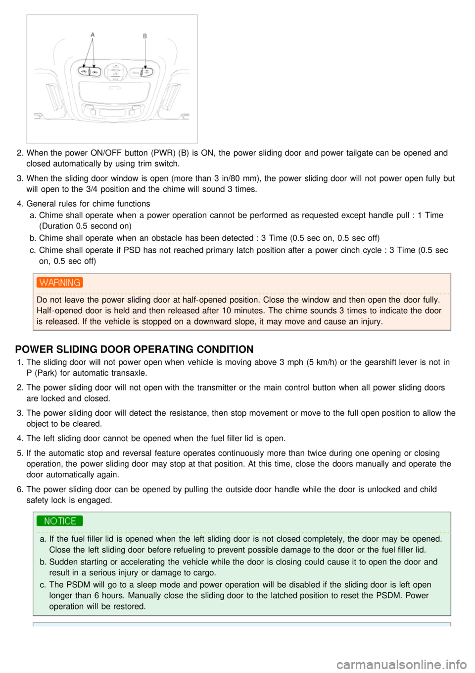
2.When the power ON/OFF button (PWR) (B) is ON, the power sliding door and power tailgate can be opened and
closed automatically by using trim switch.
3. When the sliding door window is open (more than 3 in/80 mm), the power sliding door will not power open fully but
will open to the 3/4 position and the chime will sound 3 times.
4. General rules for chime functions
a. Chime shall operate when a power operation cannot be performed as requested except handle pull : 1 Time
(Duration 0.5 second on)
b. Chime shall operate when an obstacle has been detected : 3 Time (0.5 sec on, 0.5 sec off)
c. Chime shall operate if PSD has not reached primary latch position after a power cinch cycle : 3 Time (0.5 sec
on, 0.5 sec off)
Do not leave the power sliding door at half- opened position. Close the window and then open the door fully.
Half - opened door is held and then released after 10 minutes. The chime sounds 3 times to indicate the door
is released. If the vehicle is stopped on a downward slope, it may move and cause an injury.
POWER SLIDING DOOR OPERATING CONDITION
1.The sliding door will not power open when vehicle is moving above 3 mph (5 km/h) or the gearshift lever is not in
P (Park) for automatic transaxle.
2. The power sliding door will not open with the transmitter or the main control button when all power sliding doors
are locked and closed.
3. The power sliding door will detect the resistance, then stop movement or move to the full open position to allow the
object to be cleared.
4. The left sliding door cannot be opened when the fuel filler lid is open.
5. If the automatic stop and reversal feature operates continuously more than twice during one opening or closing
operation, the power sliding door may stop at that position. At this time, close the doors manually and operate the
door automatically again.
6. The power sliding door can be opened by pulling the outside door handle while the door is unlocked and child
safety lock is engaged.
a.If the fuel filler lid is opened when the left sliding door is not closed completely, the door may be opened.
Close the left sliding door before refueling to prevent possible damage to the door or the fuel filler lid.
b. Sudden starting or accelerating the vehicle while the door is closing could cause it to open the door and
result in a serious injury or damage to cargo.
c. The PSDM will go to a sleep mode and power operation will be disabled if the sliding door is left open
longer than 6 hours. Manually close the sliding door to the latched position to reset the PSDM. Power
operation will be restored.
Page 1328 of 1575
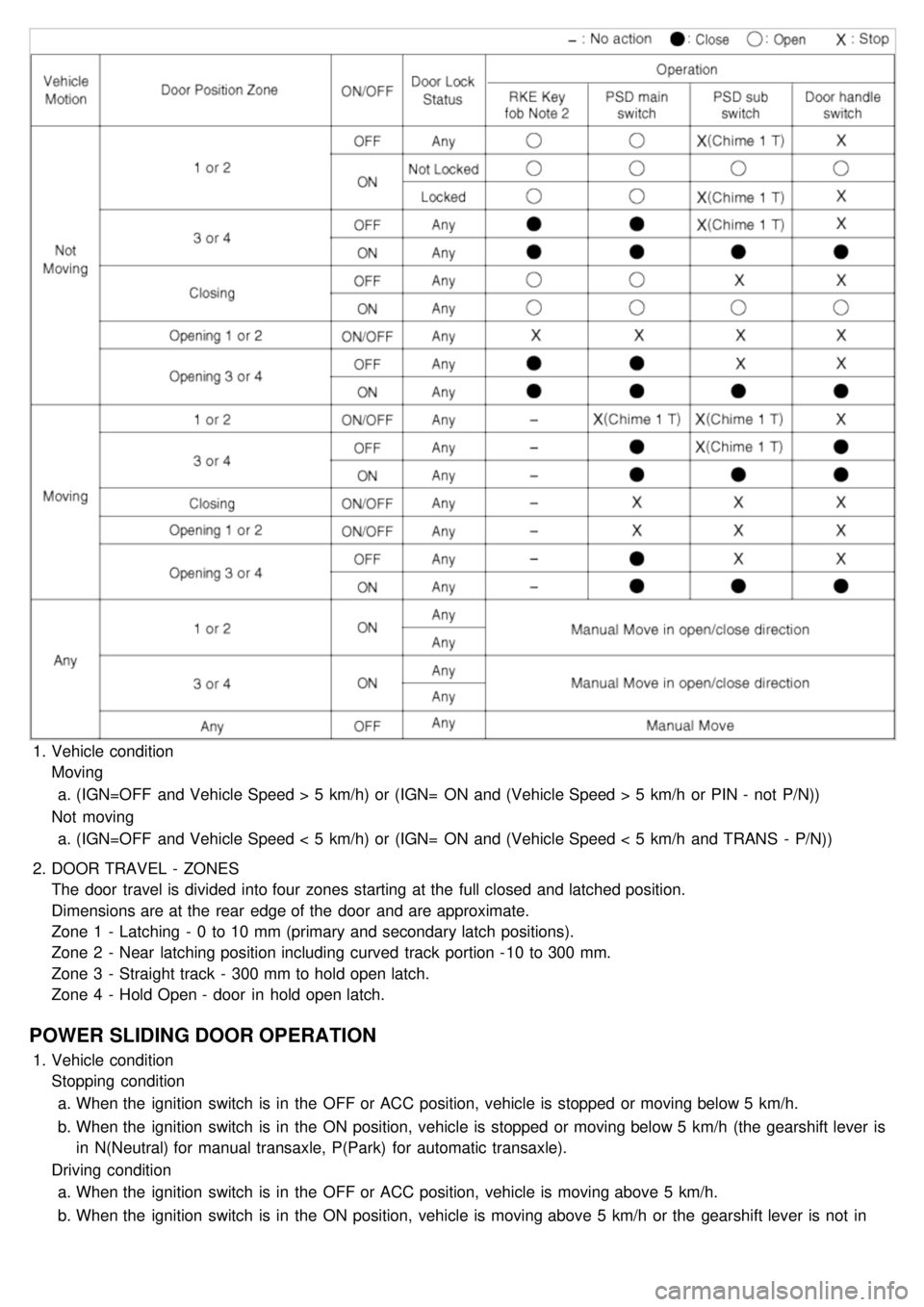
1.Vehicle condition
Moving
a. (IGN=OFF and Vehicle Speed > 5 km/h) or (IGN= ON and (Vehicle Speed > 5 km/h or PIN - not P/N))
Not moving a. (IGN=OFF and Vehicle Speed < 5 km/h) or (IGN= ON and (Vehicle Speed < 5 km/h and TRANS - P/N))
2. DOOR TRAVEL - ZONES
The door travel is divided into four zones starting at the full closed and latched position.
Dimensions are at the rear edge of the door and are approximate.
Zone 1 - Latching - 0 to 10 mm (primary and secondary latch positions).
Zone 2 - Near latching position including curved track portion - 10 to 300 mm.
Zone 3 - Straight track - 300 mm to hold open latch.
Zone 4 - Hold Open - door in hold open latch.
POWER SLIDING DOOR OPERATION
1.Vehicle condition
Stopping condition
a. When the ignition switch is in the OFF or ACC position, vehicle is stopped or moving below 5 km/h.
b. When the ignition switch is in the ON position, vehicle is stopped or moving below 5 km/h (the gearshift lever is
in N(Neutral) for manual transaxle, P(Park) for automatic transaxle).
Driving condition a. When the ignition switch is in the OFF or ACC position, vehicle is moving above 5 km/h.
b. When the ignition switch is in the ON position, vehicle is moving above 5 km/h or the gearshift lever is not in
N(Neutral) for manual transaxle, P(Park) for automatic transaxle.
Page 1369 of 1575
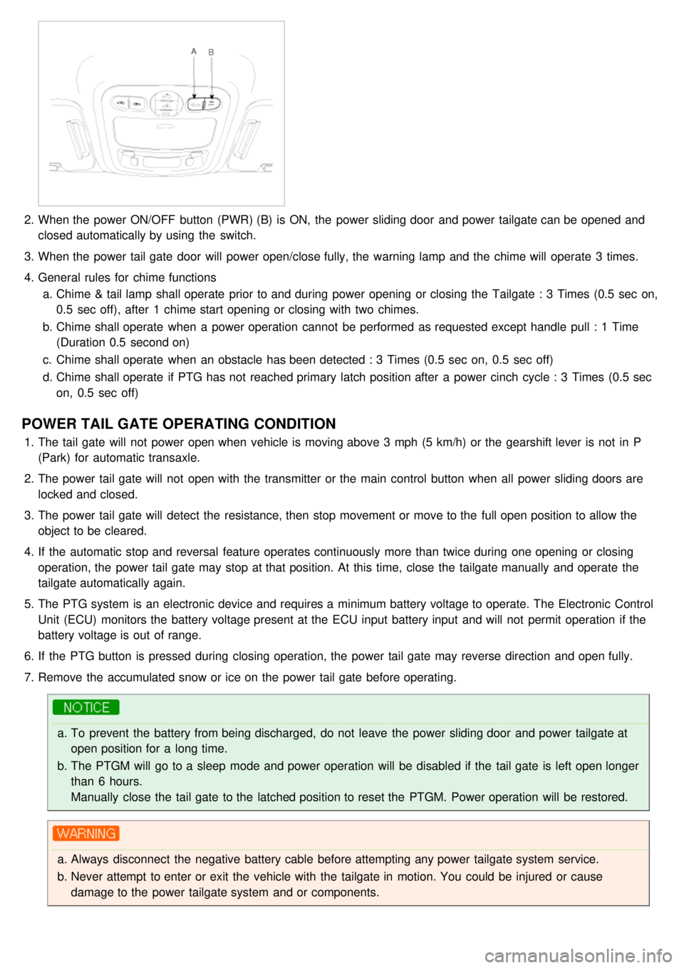
2.When the power ON/OFF button (PWR) (B) is ON, the power sliding door and power tailgate can be opened and
closed automatically by using the switch.
3. When the power tail gate door will power open/close fully, the warning lamp and the chime will operate 3 times.
4. General rules for chime functions
a. Chime & tail lamp shall operate prior to and during power opening or closing the Tailgate : 3 Times (0.5 sec on,
0.5 sec off), after 1 chime start opening or closing with two chimes.
b. Chime shall operate when a power operation cannot be performed as requested except handle pull : 1 Time
(Duration 0.5 second on)
c. Chime shall operate when an obstacle has been detected : 3 Times (0.5 sec on, 0.5 sec off)
d. Chime shall operate if PTG has not reached primary latch position after a power cinch cycle : 3 Times (0.5 sec
on, 0.5 sec off)
POWER TAIL GATE OPERATING CONDITION
1.The tail gate will not power open when vehicle is moving above 3 mph (5 km/h) or the gearshift lever is not in P
(Park) for automatic transaxle.
2. The power tail gate will not open with the transmitter or the main control button when all power sliding doors are
locked and closed.
3. The power tail gate will detect the resistance, then stop movement or move to the full open position to allow the
object to be cleared.
4. If the automatic stop and reversal feature operates continuously more than twice during one opening or closing
operation, the power tail gate may stop at that position. At this time, close the tailgate manually and operate the
tailgate automatically again.
5. The PTG system is an electronic device and requires a minimum battery voltage to operate. The Electronic Control
Unit (ECU) monitors the battery voltage present at the ECU input battery input and will not permit operation if the
battery voltage is out of range.
6. If the PTG button is pressed during closing operation, the power tail gate may reverse direction and open fully.
7. Remove the accumulated snow or ice on the power tail gate before operating.
a.To prevent the battery from being discharged, do not leave the power sliding door and power tailgate at
open position for a long time.
b. The PTGM will go to a sleep mode and power operation will be disabled if the tail gate is left open longer
than 6 hours.
Manually close the tail gate to the latched position to reset the PTGM. Power operation will be restored.
a.Always disconnect the negative battery cable before attempting any power tailgate system service.
b. Never attempt to enter or exit the vehicle with the tailgate in motion. You could be injured or cause
damage to the power tailgate system and or components.