Page 867 of 1575

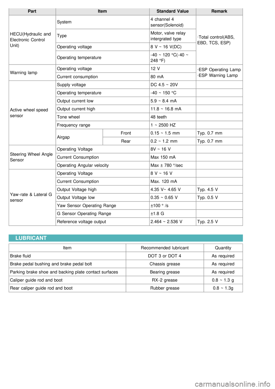
PartItemStandard ValueRemark
HECU(Hydraulic and
Electronic Control
Unit) System
4 channel 4
sensor(Solenoid)
·Total control(ABS,
EBD, TCS, ESP)
Type
Motor, valve relay
intergrated type
Operating voltage 8 V ~ 16 V(DC)
Operating temperature - 40 ~ 120 °C(- 40 ~
248 °F)
Warning lamp Operating voltage
12 V
·ESP Operating Lamp
·ESP Warning Lamp
Current consumption 80 mA
Active wheel speed
sensor Supply voltage
DC 4.5 ~ 20V
Operating temperature - 40 ~ 150 °C
Output current low 5.9 ~ 8.4 mA
Output current high 11.8 ~ 16.8 mA
Tone wheel 48 teeth
Frequency range 1 ~ 2500 HZ
Airgap Front
0.15 ~ 1.5 mm Typ. 0.7 mm
Rear 0.2 ~ 1.2 mm Typ. 0.7 mm
Steering Wheel Angle
Sensor Operating Voltage
8V ~ 16 V
Current Consumption Max 150 mA
Operating Angular velocity Max ± 780 °/sec
Yaw - rate & Lateral G
sensor Operating Voltage
8 V ~ 16 V
Current Consumption Max. 120 mA
Output Voltage high 4.35 V~ 4.65 VTyp. 4.5 V
Output Voltage low 0.35 ~ 0.65 VTyp. 0.5 V
Yaw Sensor Operating Range ±100 ° /s
G Sensor Operating Range ±1.8 G
Reference voltage output 2.464 ~ 2.536 VTyp. 2.5 V
LUBRICANT
Item Recommended lubricantQuantity
Brake fluid DOT 3 or DOT 4As required
Brake pedal bushing and brake pedal bolt Chassis greaseAs required
Parking brake shoe and backing plate contact surfaces Bearing greaseAs required
Caliper guide rod and boot RX - 2 grease0.8 ~ 1.3 g
Rear caliper guide rod and boot Rubber grease0.8 ~ 1.3g
Page 869 of 1575

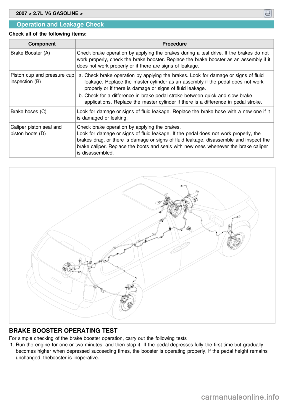
2007 > 2.7L V6 GASOLINE >
Operation and Leakage Check
Check all of the following items:
Component Procedure
Brake Booster (A) Check brake operation by applying the brakes during a test drive. If the brakes do not
work properly, check the brake booster. Replace the brake booster as an assembly if it
does not work properly or if there are signs of leakage.
Piston cup and pressure cup
inspection (B) a.
Check brake operation by applying the brakes. Look for damage or signs of fluid
leakage. Replace the master cylinder as an assembly if the pedal does not work
properly or if there is damage or signs of fluid leakage.
b. Check for a difference in brake pedal stroke between quick and slow brake
applications. Replace the master cylinder if there is a difference in pedal stroke.
Brake hoses (C) Look for damage or signs of fluid leakage. Replace the brake hose with a new one if it
is damaged or leaking.
Caliper piston seal and
piston boots (D) Check brake operation by applying the brakes.
Look for damage or signs of fluid leakage. If the pedal does not work properly, the
brakes drag, or there is damage or signs of fluid leakage, disassemble and inspect the
brake caliper. Replace the boots and seals with new ones whenever the brake caliper
is disassembled.
BRAKE BOOSTER OPERATING TEST
For simple checking of the brake booster operation, carry out the following tests
1. Run the engine for one or two minutes, and then stop it. If the pedal depresses fully the first time but gradually
becomes higher when depressed succeeding times, the booster is operating properly, if the pedal height remains
unchanged, thebooster is inoperative.
Page 878 of 1575
3.Connect the booster push rod and brake pedal with a pin (B) and install a snap clevis pin (A) to the clevis pin (B).
Grease the pin before installing the snap pin.
Always use a new snap pin.
4. Install the master cylinder.
5. Connect the vacuum hose to the brake booster.
6. After filling the brake reservoir with brake fluid, bleed the system (Refer to 'Bleeding of brake system',).
7. Check for fluid leakage.
8. Check and adjust the brake pedal for proper operation.
Page 881 of 1575
2007 > 2.7L V6 GASOLINE >
REMOVAL
Do not spill brake fluid on the vehicle; it may damage the paint; if brake fluid does contact the paint, wash it off
immediately with water.
1. Remove air cleaner mounting bolts (B) from the air cleaner mounting bracket and air cleaner body (A).(LHD)
2.Remove the air cleaner assembly (A) by removing the air cleaner mounting bolt (B) from the bracket.(LHD)
3.Remove the surge tank.(Refer to EM Gr.)
(RHD- GSL 3.8)
4. Disconnect the brake fluid level switch connector (A), and remove the reservoir cap (B).
[LHD]
[RHD]
Page 882 of 1575
5.Remove the brake fluid from the master cylinder reservoir (C) with a syringe.
6. Disconnect the brake lines (A) from the master cylinder. To prevent spills, cover the hose joints with rags or shop
towels.
7. Remove the master cylinder mounting nuts (B) and washers.
[LHD]
[RHD]
8.Remove the master cylinder(C) from the brake booster. Be careful not to bend or damage the brake lines when
removing the master cylinder.
INSTALLATION
1.Install the master cylinder on the brake booster with 2 nuts.
2. Connect the two brake tubes and the brake fluid level sensor connector.
[LHD]
Page 883 of 1575
[RHD]
3.Fill the brake reservoir with the brake fluid and bleed the brake system (Refer to 'Bleeding of brake system').
DISASSEMBLY
1.Remove the reservoir cap and drain the brake fluid into a suitable container.
2. Remove the fluid level sensor.
3. Remove the reservoir from the master cylinder, after remove mounting screw (A).
[LHD]
4.Remove the retainer ring (A) by using the snap ring pliers.
Page 884 of 1575
5.Remove the primary piston assembly (A).
6. Remove the pin (C) with the secondary piston (B) pushed completely using a screwdriver. Remove the secondary
piston assembly (B).
Do not disassemble the primary and secondary piston assembly.
INSPECTION
1.Check the master cylinder bore for rust or scratching.
2. Check the master cylinder for wear or damage. If necessary, clean or replace the cylinder.
a.If the cylinder bore is damaged, replace the master cylinder assembly.
b. Wash the contaminated parts in alcohol.
REASSEMBLY
1.Apply genuine brake fluid to the rubber parts of the cylinder kit and grommets.
2. Carefully insert the springs and pistons in the proper direction.
3. Press the piston with a screwdriver (A) and install the cylinder pin (B).
Page 929 of 1575

1.ABS WARNING LAMP MODULE
The active ABS warning lamp module indicates the selftest and failure status of the ABS.The ABS warning lamp
shall be on:
a. During the initialization phase after IGN ON. (continuously 3 seconds).
b. In the event of inhibition of ABS functions by failure.
c. During diagnostic mode.
d. When the ECU Connector is seperated from ECU.
2. PARKING/EBD WARNING LAMP MODULE
The active EBD warning lamp module indicates the selftest and failure status of the EBD.However, in case the
Parking Brake Switch is turned on, the EBD warning lamp is always turned on regardless of EBD functions.The
EBD warning lamp shall be on:
a. During the initialization phase after IGN ON. (continuously 3 seconds).
b. When the Parking Brake Switch is ON or brake fluid level is low.
c. When the EBD function is out of order.
d. During diagnostic mode.
e. When the ECU Connector is seperated from ECU.
ABS CONTROL
1.NORMAL BRAKING without ABS
Inlet valve(EV)Outlet valve(AV)Pump motor
Operation OpenCloseOFF