2007 KIA CARNIVAL brake fluid
[x] Cancel search: brake fluidPage 943 of 1575

CHECK FOR BLOWN FUSE
Check continuity of fuse (10A) from the engine compartment junction block.
Is there continuity?
▶ Repair an open in the wire between ABS fuse and 1 of cluster connector.
▶ Replace the blown fuse.
DETECTING CONDITION
Trouble Symptoms Possible Cause
If the HECU detects trouble, it lights the ABS warning lamp while at
the same time prohibiting ABS control. At this time, the HECU
records a DTC in memory.Even though the normal code is output, the
ABS warning lamp remains ON, then the cause may be probably an
open or short in the ABS warning lamp circuit. a.
An open in the wire
b. Inoperative instrument cluster assembly
c. Inoperative ABS warning lamp module
d. Inoperative HECU
INSPECTION PROCEDURES
CHECK DTC OUTPUT.
1. Connect the Scan Tool to the 16P data link connector located behind the driver's side kick panel.
2. Check the DTC output using Scan Tool.
Is DTC output ?
▶ Repair circuit indicated by code output.
▶ Check instrument cluster.
CHECK INSTRUMENT CLUSTER
Disconnect the cluster connector and turn the ignition switch ON.
Does the ABS warning lamp remains ON?
▶ Replace the instrument cluster.
▶ Check for open the wire.
CHECK FOR OPEN IN THE WIRE
Check for continuity in the wire between cluster and ABS control module.
Is there continuity?
▶ Replace the ABS control module and recheck.
▶ Repair an open in the wire between cluster and ABS control module.
BLEEDING OF BRAKE SYSTEM
1. Remove the reservoir cap and fill the brake reservoir with brake fluid.
If there is any brake fluid on any painted surface, wash it off immediately.
Page 944 of 1575

When pressure bleeding, do not depress the brake pedal.
Recommended fluid........ DOT3 or DOT4
2. Connect a clear plastic tube to the brake caliper bleeder plug and insert the other end of the tube into a half filled
clear plastic bottle.
3.Connect the scan tool to the data link connector located underneath the dash panel.
4.Select and operate according to the instructions on the scan tool screen.
You must obey the maximum operating time of the ABS motor with the scan tool to prevent the motor pump
from burning.
(1) Select kia vehicle diagnosis.
(2) Select vehicle name.
(3) Select Anti- Lock Brake system.
(4) Select air bleeding mode.
(5) Press "YES" to operate motor pump and solenoid valve.
Page 945 of 1575

(6)Wait 60 sec. before operating the air bleeding again. (If not, you may damage the motor.)
5.Pump the brake pedal several times, and then loosen the bleeder screw until fluid starts to run out without bubbles.
Then close the bleeder screw.
6. Repeat step 5 until there are no more bubbles in the fluid for each wheel.
7.Tighten the bleeder screw.
Bleed screw tightening torque:
7~1 3 Nm (0.7 ~1.3 kgf·m, 5.06 ~ 9.4 lb - ft)
DIAGNOSTIC TROUBLE CODE CHART(DTC)
Page 975 of 1575

The active EBD warning lamp module indicates the self - test and failure status of the EBD. However, in case the
Parking Brake Switch is turned on, the EBD warning lamp is always turned on regardless of EBD functions. The EBD
warning lamp shall be on:a. During the initialization phase after IGN ON. (continuously 3 seconds).
b. When the Parking Brake Switch is ON or brake fluid level is low.
c. When the EBD function is out of order .
d. During diagnostic mode.
e. When the ECU Connector is seperated from ECU.
ESP Warning Lamp (ESP system)
The ESP warning lamp indicates the self - test and failure status of the ESP.
The ESP warning lamp is turned on under the following conditions :
a. During the initialization phase after IGN ON. (continuously 3 seconds).
b. In the event of inhibition of ESP functions by failure.
c. When driver turn off the ESP function by on/off switch.
d. During diagnostic mode.
ESC Function Lamp (ESC system)
The ESP function lamp indicates the self - test and operating status of the ESP.
The ESP Function lamp operates under the following conditions :
a. During the initialization phase after IGN ON. (continuously 3 seconds).
b. When the ESP control is operating. (Blinking - 2Hz)
ESP On/Off Switch (ESP system)
The ESP On/Off Switch shall be used to toggle the ESP function between On/Off states based upon driver input.
The On/Off switch shall be a normally open, momentary contact switch.
Initial status of the ESP function is on and the switch is used to request an ESC status change.
Page 1227 of 1575

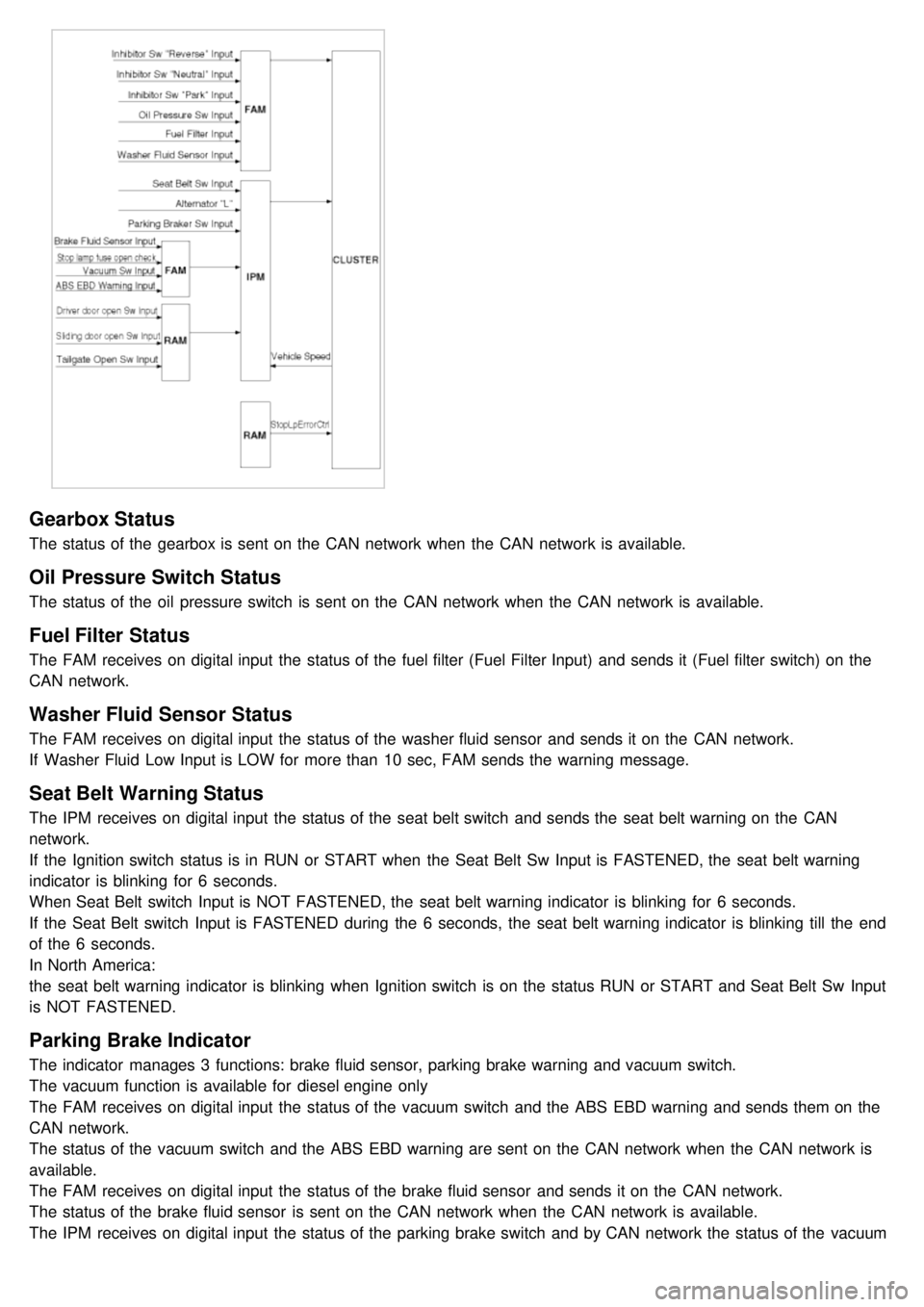
Easy Access
1.Description
The easy access function permits automatic rearward movement of the driver seat when the key is removed from
the cylinder. Automatic forward movement of the driver seat will take place when the key is inserted into the
cylinder. This function will be enabled on IMS equipped vehicles when the AUTO button is pressed.
Inhibit Switch should be in P- Position for the Easy Access operation.
2. Functional Diagram
Driver Information
Cluster Indicators
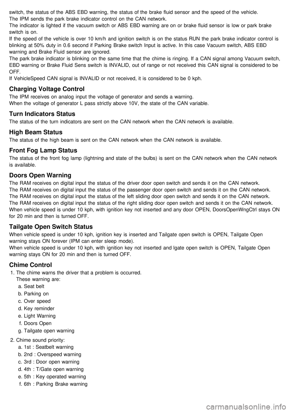
1.The instument cluster indicators listed below are controlled by the In- Panel Module (IPM), Front Area Module
(FAM), or Rear Area Module (RAM) as applicable.
These indicators are:
a. Gearbox status
b. Oil pressure
c. Sediment fuel filter
d. Vacuum
e. Brake fluid
f. Washer fluid
g. Seat belt
h. Park brake
i. Charging voltage
j. Turn indicators
k. High beam
l. Front fog
m. Doors open
n. Tailgate open
o. Stop lamp failure front and rear
2. Functional Diagram
Page 1228 of 1575

Gearbox Status
The status of the gearbox is sent on the CAN network when the CAN network is available.
Oil Pressure Switch Status
The status of the oil pressure switch is sent on the CAN network when the CAN network is available.
Fuel Filter Status
The FAM receives on digital input the status of the fuel filter (Fuel Filter Input) and sends it (Fuel filter switch) on the
CAN network.
Washer Fluid Sensor Status
The FAM receives on digital input the status of the washer fluid sensor and sends it on the CAN network.
If Washer Fluid Low Input is LOW for more than 10 sec, FAM sends the warning message.
Seat Belt Warning Status
The IPM receives on digital input the status of the seat belt switch and sends the seat belt warning on the CAN
network.
If the Ignition switch status is in RUN or START when the Seat Belt Sw Input is FASTENED, the seat belt warning
indicator is blinking for 6 seconds.
When Seat Belt switch Input is NOT FASTENED, the seat belt warning indicator is blinking for 6 seconds.
If the Seat Belt switch Input is FASTENED during the 6 seconds, the seat belt warning indicator is blinking till the end
of the 6 seconds.
In North America:
the seat belt warning indicator is blinking when Ignition switch is on the status RUN or START and Seat Belt Sw Input
is NOT FASTENED.
Parking Brake Indicator
The indicator manages 3 functions: brake fluid sensor, parking brake warning and vacuum switch.
The vacuum function is available for diesel engine only
The FAM receives on digital input the status of the vacuum switch and the ABS EBD warning and sends them on the
CAN network.
The status of the vacuum switch and the ABS EBD warning are sent on the CAN network when the CAN network is
available.
The FAM receives on digital input the status of the brake fluid sensor and sends it on the CAN network.
The status of the brake fluid sensor is sent on the CAN network when the CAN network is available.
The IPM receives on digital input the status of the parking brake switch and by CAN network the status of the vacuum
switch, the status of the ABS EBD warning, the status of the brake fluid sensor and the speed of the vehicle.
Page 1229 of 1575

switch, the status of the ABS EBD warning, the status of the brake fluid sensor and the speed of the vehicle.
The IPM sends the park brake indicator control on the CAN network.
The indicator is lighted if the vacuum switch or ABS EBD warning are on or brake fluid sensor is low or park brake
switch is on.
If the speed of the vehicle is over 10 km/h and ignition switch is on the status RUN the park brake indicator control is
blinking at 50% duty in 0.6 second if Parking Brake switch Input is active. In this case Vacuum switch, ABS EBD
warning and Brake Fluid sensor are ignored.
The park brake indicator is blinking on the same time that the chime is ringing. If a CAN signal among Vacuum switch,
EBD warning or Brake Fluid Sens switch is INVALID, out of range or not received this CAN signal is considered to be
OFF.
If VehicleSpeed CAN signal is INVALID or not received, it is considered to be 0 kph.
Charging Voltage Control
The IPM receives on analog input the voltage of generator and sends a warning.
When the voltage of generator L pass strictly above 10V, the state of the CAN variable.
Turn Indicators Status
The status of the turn indicators are sent on the CAN network when the CAN network is available.
High Beam Status
The status of the high beam is sent on the CAN network when the CAN network is available.
Front Fog Lamp Status
The status of the front fog lamp (lightning and state of the bulbs) is sent on the CAN network when the CAN network
is available.
Doors Open Warning
The RAM receives on digital input the status of the driver door open switch and sends it on the CAN network.
The RAM receives on digital input the status of the passenger door open switch and sends it on the CAN network.
The RAM receives on digital input the status of the left sliding door open switch and sends it on the CAN network.
The RAM receives on digital input the status of the right sliding door open switch and sends it on the CAN network.
When vehicle speed is under 10 kph, with ignition key not inserted and any door OPEN, DoorsOpenWngCtrl stays ON
for 20 min and then is turned OFF.
Tailgate Open Switch Status
When vehicle speed is under 10 kph, ignition key is inserted and Tailgate open switch is OPEN, Tailgate Open
warning stays ON forever (IPM can enter sleep mode).
When vehicle speed is under 10 kph, with ignition key not inserted and lgate open switch is OPEN, Tailgate Open
warning stays ON for 20 min and then is turned OFF.
Chime Control
1.The chime warns the driver that a problem is occurred.
These warning are:
a. Seat belt
b. Parking on
c. Over speed
d. Key reminder
e. Light Warning
f. Doors Open
g. Tailgate open warning
2. Chime sound priority:
a. 1st : Seatbelt warning
b. 2nd : Overspeed warning
c. 3rd : Door open warning
d. 4th : T/Gate open warning
e. 5th : Key operated warning
f. 6th : Parking Brake warning
Page 1242 of 1575

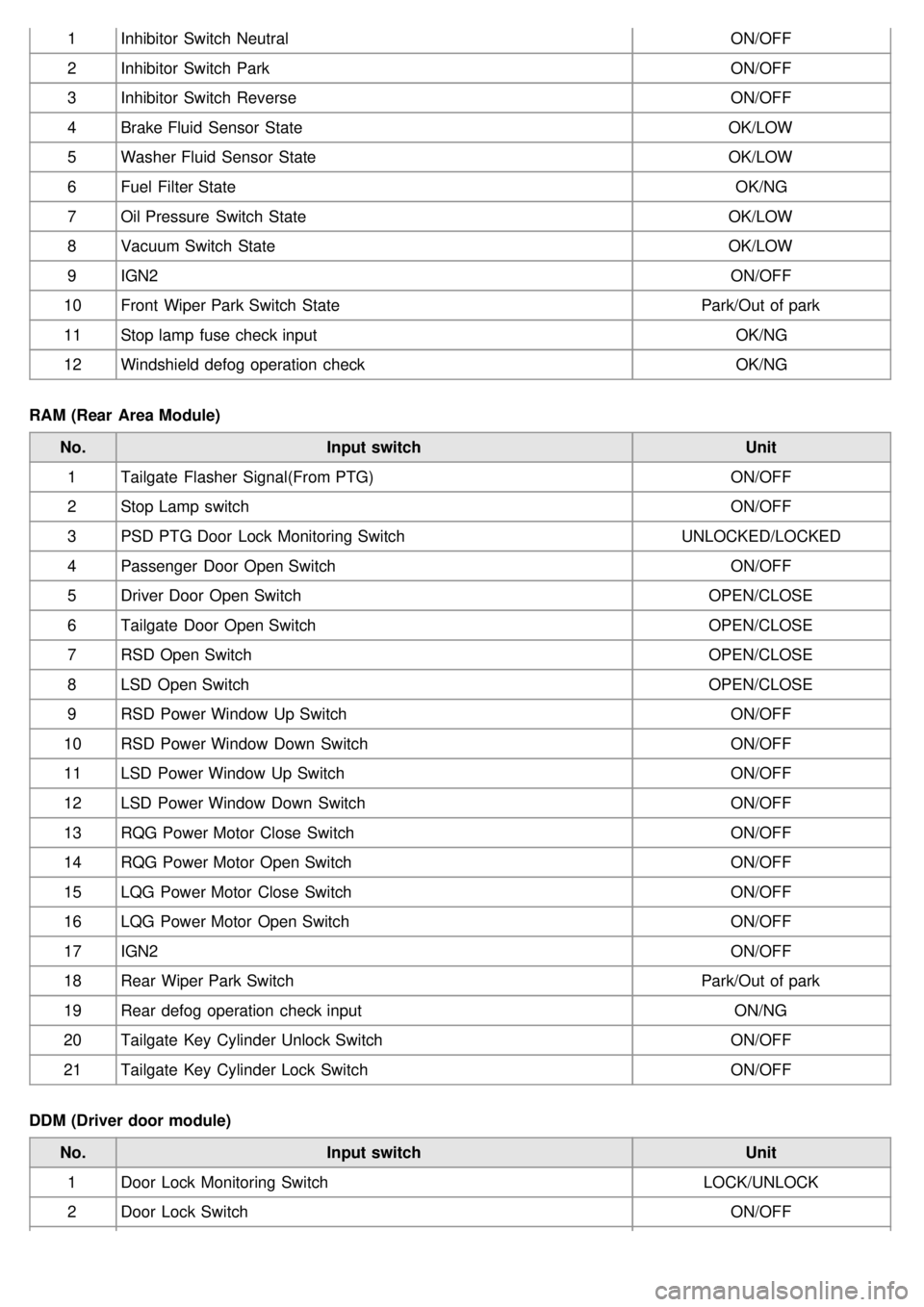
1Inhibitor Switch Neutral ON/OFF
2 Inhibitor Switch Park ON/OFF
3 Inhibitor Switch Reverse ON/OFF
4 Brake Fluid Sensor State OK/LOW
5 Washer Fluid Sensor State OK/LOW
6 Fuel Filter State OK/NG
7 Oil Pressure Switch State OK/LOW
8 Vacuum Switch State OK/LOW
9 IGN2 ON/OFF
10 Front Wiper Park Switch State Park/Out of park
11 Stop lamp fuse check input OK/NG
12 Windshield defog operation check OK/NG
RAM (Rear Area Module) No. Input switch Unit
1 Tailgate Flasher Signal(From PTG) ON/OFF
2 Stop Lamp switch ON/OFF
3 PSD PTG Door Lock Monitoring Switch UNLOCKED/LOCKED
4 Passenger Door Open Switch ON/OFF
5 Driver Door Open Switch OPEN/CLOSE
6 Tailgate Door Open Switch OPEN/CLOSE
7 RSD Open Switch OPEN/CLOSE
8 LSD Open Switch OPEN/CLOSE
9 RSD Power Window Up Switch ON/OFF
10 RSD Power Window Down Switch ON/OFF
11 LSD Power Window Up Switch ON/OFF
12 LSD Power Window Down Switch ON/OFF
13 RQG Power Motor Close Switch ON/OFF
14 RQG Power Motor Open Switch ON/OFF
15 LQG Power Motor Close Switch ON/OFF
16 LQG Power Motor Open Switch ON/OFF
17 IGN2 ON/OFF
18 Rear Wiper Park Switch Park/Out of park
19 Rear defog operation check input ON/NG
20 Tailgate Key Cylinder Unlock Switch ON/OFF
21 Tailgate Key Cylinder Lock Switch ON/OFF
DDM (Driver door module) No. Input switch Unit
1 Door Lock Monitoring Switch LOCK/UNLOCK
2 Door Lock Switch ON/OFF