Page 692 of 1575
2007 > 2.7L V6 GASOLINE >
DESCRIPTION
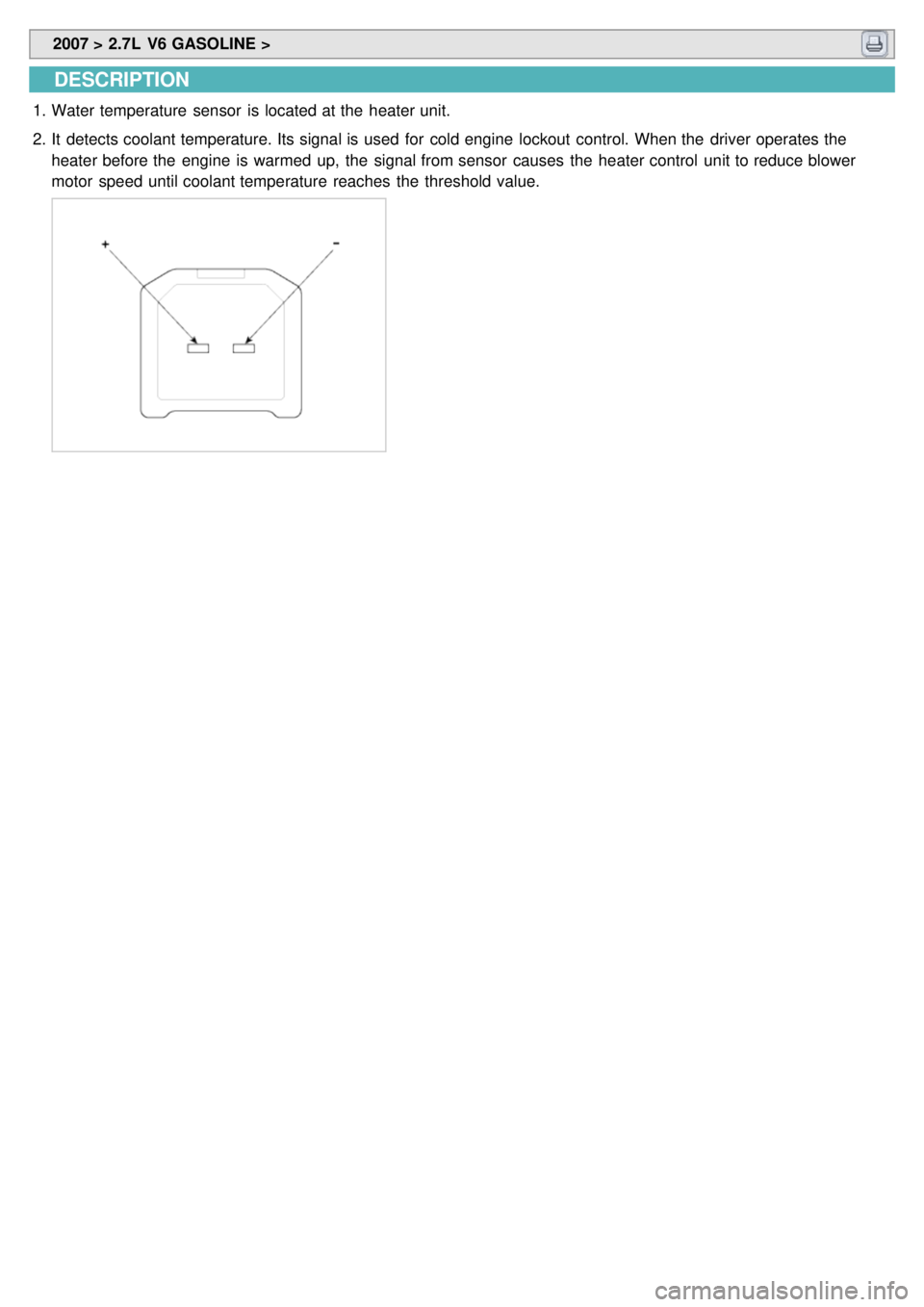
1.Water temperature sensor is located at the heater unit.
2. It detects coolant temperature. Its signal is used for cold engine lockout control. When the driver operates the
heater before the engine is warmed up, the signal from sensor causes the heater control unit to reduce blower
motor speed until coolant temperature reaches the threshold value.
Page 697 of 1575
2007 > 2.7L V6 GASOLINE >
DESCRIPTION
1.The ambient temperature sensor is located at the front of the condenser and detects ambient air temperature. It is
a negative type thermistor; resistance will increase with lower temperature, and decrease with higher temperatures.
2. The sensor output will be used for discharge temperature control, temperature regulation door control, blower
motor level control, mix mode control and in - car humidity control.
If the ambient temperature is below - 3°C (26.2°F), the A/C compressor will be stopped.
The compressor will be operated by manual operating.
Page 713 of 1575

2007 > 2.7L V6 GASOLINE >
REPLACEMENT
1.Disconnect the negative ( - ) battery terminal.
2. Recover the refrigerant with a recovery/ recycling/ charging station. (Refer to HA - 8)
3. When the engine is cool, drain the engine coolant from the radiator.
4. Remove the bolts (A) and the expansion valve (B) from the evaporator core.
Plug or cap the lines immediately after disconnecting them to avoid moisture and dust contamination.
5.Disconnect the inlet (A) and outlet (B) heater hoses from the heater unit.
Engine coolant will run out when the hoses are disconnected; drain it into a clean drip pan. Be sure not to let
coolant spill on electrical parts or painted surfaces. If any coolant spills, rinse it off immediately.
6. Remove the crash pad (Refer to BD group).
7. Remove the cowl cross bar assembly. (Refer to BD group)
8. Disconnect the connectors from the temperature control actuator, the mode control actuator and the evaporator
temperature sensor.
9. Remove the heater & blower unit after loosening 3 mounting bolts.
Page 714 of 1575
10.Remove the blower unit (B) from heater unit after loosening 2 screws.
11.Remove the self - tapping screws (A) and remove the PTC heater unit (B) or cover. (In case of PTC heater)
12.Remove the heater core (B) after remove the cover (A).
13.Loosen a screw and then remove the heater unit cover(A).
Page 737 of 1575
2007 > 2.7L V6 GASOLINE >
INSPECTION
Inspect the PTC operation by confirmation logic as below.
1. Entering method
(1) Set the floor mode, maximum heating
(2) Turn off the blower switch
(3) Press the intake button more than 5 times.
(4) Indicator of entire button is flashed with an interval of 0.5 seconds continuously (Manual).
Graphics of the entire LCD display switch on and off with an interval of 0.5 seconds continuously (Automatic)
(5) Confirm the PTC operation by operating the blower switch
Manual : 1~4 step, Automatic: 1~8step.
(6) Each PTC relay is operated with an interval of 3 seconds.
(7) Execute the PTC operation by confirmation logic for 30 seconds.
2. Cancellation method
(1) Select the A/C button or intake button.
(2) IG "OFF".
(3) Cancel the logic after 30 seconds automatically.
3. If the PTC operation is not operated, substitute with a known- good PTC and check for proper operation.
If the problem is corrected, replace the PTC.
Page 745 of 1575
Page 746 of 1575
2007 > 2.7L V6 GASOLINE >
INSPECTION
1.Connect the battery voltage and check the blower motor rotation.
2.If the blower motor voltage is not operated well, substitute with a known- good blower motor and check for proper
operation.
3. If the problem is corrected, replace the blower motor.
REPLACEMENT
1.Disconnect the negative ( - ) battery terminal.
2. Disconnect the connector (A) of the blower motor.
3. Remove the blower motor (A) after loosening the mounting screws.
4.Installation is the reverse order of removal.
Page 753 of 1575
2007 > 2.7L V6 GASOLINE >
INSPECTION
1.Ignition "ON".
2. Manually operate the control switch and measure the voltage of blower motor between pin 1 and 2.
3. Select the control switch to raise voltage until high speed.
Fan Voltage
Manual
1 STEP 4.5 ± 0.5V
2 STEP 5.7 ± 0.5V
3 STEP 6.9 ± 0.5V
4 STEP 8.1 ± 0.5V
5 STEP 9.3 ± 0.5V
6 STEP 10.3 ± 0.5V
7 STEP Battary(+)
REPLACEMENT
1.Disconnect the negative ( - ) battery terminal.
2. Remove the luggage side trim (Refer to BD - ).
3. Disconnect the power mosfet connector (A).
4. Remove the power mosfet (B) after loosening the mounting screws.