Page 771 of 1575
2007 > 2.7L V6 GASOLINE >
INSPECTION
1.Ignition "ON"
2. Manually operate the control switch and measure the voltage of blower motor between pin 1 and 2.
3. Select the control switch to raise voltage until high speed.
Specification
Fan Motor Voltage
Manual
First speed 4.0 ±0.5V
Second speed 5.1 ±0.5V
Third speed 6.2 ±0.5V
Fourth speed 7.3 ±0.5V
Fifth speed 8.4 ±0.5V
Sixth speed 9.5 ±0.5V
Seventh speed 10.5 ±0.5V
eighth speed Battary(+)
*AUTO COOLING: Auto speed (4.5V~B+)
*AUTO HEATING: Auto speed (4.5V~10.5V)
4. If the measured voltage is not specification, substitute with a known- good power mosfet and check for proper
operation.
5. If the problem is corrected, replace the power mosfet.
REPLACEMENT
1.Disconnect the negative ( - ) battery terminal.
2. Disconnect the power mosfet connector (A) at the connecting part between heater and blower unit.
3. Remove the power mosfet (B) after loosening the mounting screws.
Page 778 of 1575
2007 > 2.7L V6 GASOLINE >
DESCRIPTION
1.The intake actuator is located at the blower unit.
2. It regulates the intake door by signal from control unit.
3. Pressing the intake selection switch will shift between recirculation and fresh air modes.
Page 779 of 1575
2007 > 2.7L V6 GASOLINE >
INSPECTION
1.Ignition "OFF"
2. Disconnect the intake actuator connector.
3. Verify that the actuator operates to the recirculation position when connecting 12V to the terminal 3 and grounding
terminal 4.
4. Verify that the intake actuator operates to the fresh position when connecting in the reverse.
5.If the intake actuator is not operated well, substitute with a known- good intake actuator and check for proper
operation.
6. If the problem is corrected, replace the intake actuator.
REPLACEMENT
1.Disconnect the negative ( - ) battery terminal.
2. Remove the glove box (Refer to BD group).
3. Disconnect the intake actuator connector.
4. Loosen the mounting screw and then remove the intake actuator (A) from the blower unit.
5.Installation is the reverse order of removal.
Page 783 of 1575
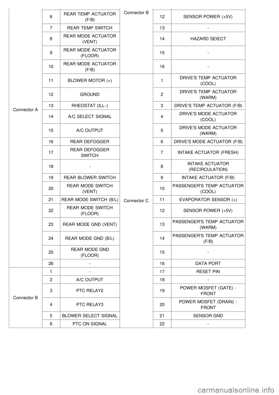
Connector AConnector B
6 REAR TEMP ACTUATOR
(F/B) 12
SENSOR POWER (+5V)
7 REAR TEMP SWITCH 13-
8 REAR MODE ACTUATOR
(VENT) 14
HAZARD SEIECT
9 REAR MODE ACTUATOR
(FLOOR) 15
-
10 REAR MODE ACTUATOR
(F/B) 16
-
11 BLOWER MOTOR (+)
Connector C1
DRIVE'S TEMP ACTUATOR
(COOL)
12 GROUND 2DRIVE'S TEMP ACTUATOR
(WARM)
13 RHEOSTAT (ILL- ) 3DRIVE'S TEMP ACTUATOR (F/B)
14 A/C SELECT SIGNAL 4DRIVE'S MODE ACTUATOR
(COOL)
15 A/C OUTPUT 5DRIVE'S MODE ACTUATOR
(WARM)
16 REAR DEFOGGER 6DRIVE'S MODE ACTUATOR (F/B)
17 REAR DEFOGGER
SWITCH 7
INTAKE ACTUATOR (FRESH)
18 - 8INTAKE ACTUATOR
(RECIRCULATION)
19 REAR BLOWER SWITCH 9INTAKE ACTUATOR (F/B)
20 REAR MODE SWITCH
(VENT) 10
PASSENGER'S TEMP ACTUATOR
(COOL)
21 REAR MODE SWITCH (B/L) 11EVAPORATOR SENSOR (+)
22 REAR MODE SWITCH
(FLOOR) 12
SENSOR POWER (+5V)
23 REAR MODE GND (VENT) 13PASSENGER'S TEMP ACTUATOR
(WARM)
24 REAR MODE GND (B/L) 14PASSENGER'S TEMP ACTUATOR
(F/B)
25 REAR MODE GND
(FLOOR) 15
-
26 - 16DATA PORT
Connector B 1
- 17RESET PIN
2 A/C OUTPUT 18-
3 PTC RELAY2 19POWER MOSFET (GATE) -
FRONT
4 PTC RELAY3 20POWER MOSFET (DRAIN) -
FRONT
5 BLOWER SELECT SIGNAL 21SENSOR GND
6 PTC ON SIGNAL 22-
Page 787 of 1575
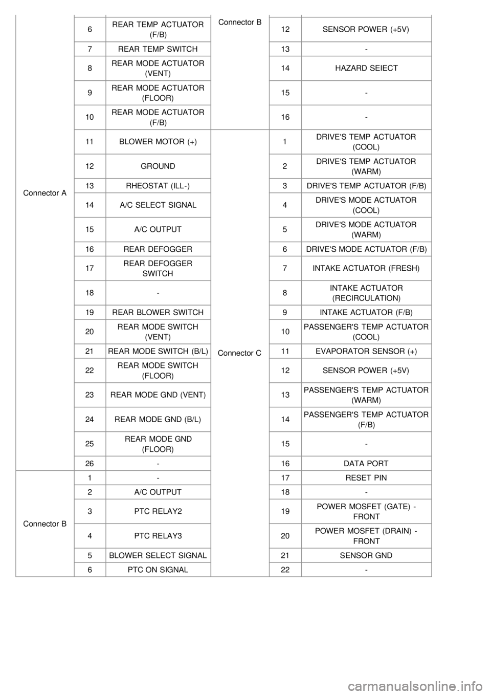
Connector AConnector B
6 REAR TEMP ACTUATOR
(F/B) 12
SENSOR POWER (+5V)
7 REAR TEMP SWITCH 13-
8 REAR MODE ACTUATOR
(VENT) 14
HAZARD SEIECT
9 REAR MODE ACTUATOR
(FLOOR) 15
-
10 REAR MODE ACTUATOR
(F/B) 16
-
11 BLOWER MOTOR (+)
Connector C1
DRIVE'S TEMP ACTUATOR
(COOL)
12 GROUND 2DRIVE'S TEMP ACTUATOR
(WARM)
13 RHEOSTAT (ILL- ) 3DRIVE'S TEMP ACTUATOR (F/B)
14 A/C SELECT SIGNAL 4DRIVE'S MODE ACTUATOR
(COOL)
15 A/C OUTPUT 5DRIVE'S MODE ACTUATOR
(WARM)
16 REAR DEFOGGER 6DRIVE'S MODE ACTUATOR (F/B)
17 REAR DEFOGGER
SWITCH 7
INTAKE ACTUATOR (FRESH)
18 - 8INTAKE ACTUATOR
(RECIRCULATION)
19 REAR BLOWER SWITCH 9INTAKE ACTUATOR (F/B)
20 REAR MODE SWITCH
(VENT) 10
PASSENGER'S TEMP ACTUATOR
(COOL)
21 REAR MODE SWITCH (B/L) 11EVAPORATOR SENSOR (+)
22 REAR MODE SWITCH
(FLOOR) 12
SENSOR POWER (+5V)
23 REAR MODE GND (VENT) 13PASSENGER'S TEMP ACTUATOR
(WARM)
24 REAR MODE GND (B/L) 14PASSENGER'S TEMP ACTUATOR
(F/B)
25 REAR MODE GND
(FLOOR) 15
-
26 - 16DATA PORT
Connector B 1
- 17RESET PIN
2 A/C OUTPUT 18-
3 PTC RELAY2 19POWER MOSFET (GATE) -
FRONT
4 PTC RELAY3 20POWER MOSFET (DRAIN) -
FRONT
5 BLOWER SELECT SIGNAL 21SENSOR GND
6 PTC ON SIGNAL 22-
Page 1221 of 1575
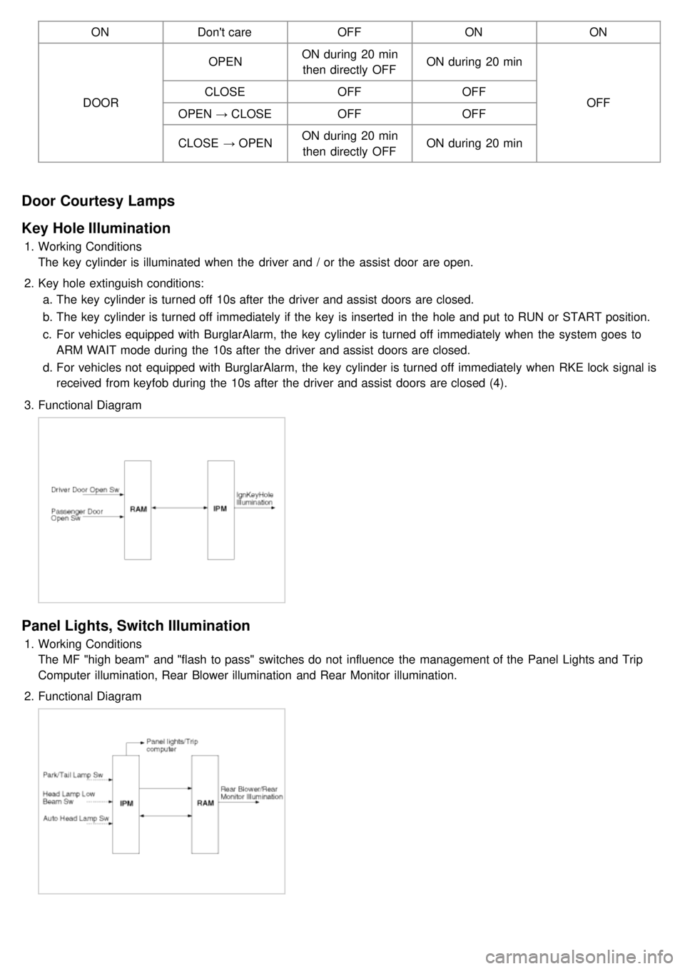
ONDon't care OFFONON
DOOR OPEN
ON during 20 min
then directly OFF ON during 20 min
OFF
CLOSE
OFFOFF
OPEN → CLOSE OFF OFF
CLOSE → OPEN ON during 20 min
then directly OFF ON during 20 min
Door Courtesy Lamps
Key Hole Illumination
1.
Working Conditions
The key cylinder is illuminated when the driver and / or the assist door are open.
2. Key hole extinguish conditions:
a. The key cylinder is turned off 10s after the driver and assist doors are closed.
b. The key cylinder is turned off immediately if the key is inserted in the hole and put to RUN or START position.
c. For vehicles equipped with BurglarAlarm, the key cylinder is turned off immediately when the system goes to
ARM WAIT mode during the 10s after the driver and assist doors are closed.
d. For vehicles not equipped with BurglarAlarm, the key cylinder is turned off immediately when RKE lock signal is
received from keyfob during the 10s after the driver and assist doors are closed (4).
3. Functional Diagram
Panel Lights, Switch Illumination
1.Working Conditions
The MF "high beam" and "flash to pass" switches do not influence the management of the Panel Lights and Trip
Computer illumination, Rear Blower illumination and Rear Monitor illumination.
2. Functional Diagram
Page 1246 of 1575
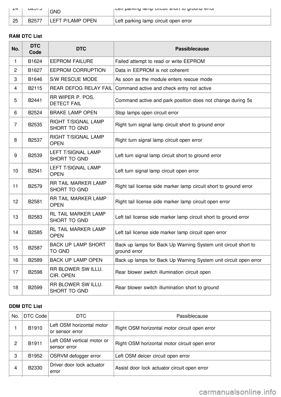
24B2575
GND Left parking lamp circuit short to ground error
25 B2577 LEFT P/LAMP OPEN Left parking lamp circuit open error
RAM DTC List No. DTC
Code DTC
Passiblecause
1 B1624 EEPROM FAILURE Failed attempt to read or write EEPROM
2 B1627 EEPROM CORRUPTION Data in EEPROM is not coherent
3 B1646 S/W RESCUE MODE As soon as the module enters rescue mode
4 B2115 REAR DEFOG RELAY FAIL Command active and check entry not active
5 B2441 RR WIPER P. POS.
DETECT FAIL Command active and park position does not change during 5s
6 B2524 BRAKE LAMP OPEN Stop lamps open circuit error
7 B2535 RIGHT T/SIGNAL LAMP
SHORT TO GND Right turn signal lamp circuit short to ground error
8 B2537 RIGHT T/SIGNAL LAMP
OPEN Right turn signal lamp circuit open error
9 B2539 LEFT T/SIGNAL LAMP
SHORT TO GND Left turn signal lamp circuit short to ground error
10 B2541 LEFT T/SIGNAL LAMP
OPEN Left turn signal lamp circuit open error
11 B2579 RR TAIL MARKER LAMP
SHORT TO GND Right tail license side marker lamp circuit short to ground error
12 B2581 RR TAIL MARKER LAMP
OPEN Right tail license side marker lamp circuit open error
13 B2583 RL TAIL MARKER LAMP
SHORT TO GND Left tail license side marker lamp circuit short to ground error
14 B2585 RL TAIL MARKER LAMP
OPEN Left tail license side marker lamp circuit open error
15 B2587 BACK UP LAMP SHORT
TO GND Back up lamps for Back Up Warning System unit circuit short to
ground error
16 B2589 BACK UP LAMP OPEN Back up lamps for Back Up Warning System unit circuit open error
17 B2598 RR BLOWER SW ILLU.
CIR. OPEN Rear blower switch illumination circuit open
18 B2599 RR BLOWER SW ILLU.
SHORT TO GND Rear blower switch illumination short to ground
DDM DTC List No. DTC Code DTC Passiblecause
1 B1910 Left OSM horizontal motor
or sensor error Right OSM horizontal motor circuit open error
2 B1911 Left OSM vertical motor or
sensor error Right OSM horizontal motor circuit open error
3 B1952 OSRVM defogger error Left OSM deicer circuit open error
4 B2330 Driver door lock actuator
error Assist door lock actuator circuit open error
Page 1249 of 1575
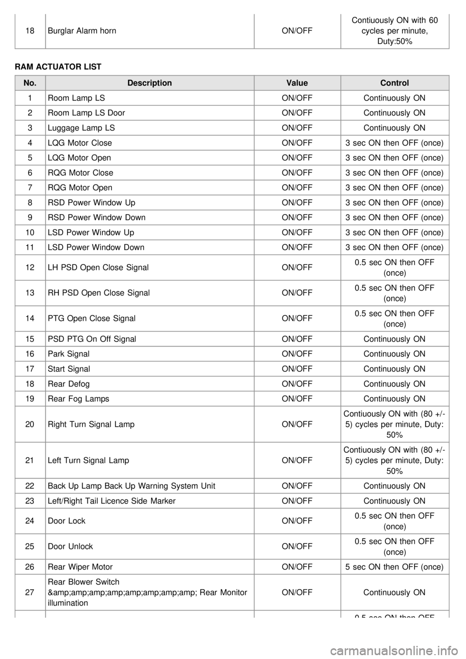
18Burglar Alarm horn ON/OFFContiuously ON with 60
cycles per minute, Duty:50%
RAM ACTUATOR LIST No. Description ValueControl
1 Room Lamp LS ON/OFFContinuously ON
2 Room Lamp LS Door ON/OFFContinuously ON
3 Luggage Lamp LS ON/OFFContinuously ON
4 LQG Motor Close ON/OFF3 sec ON then OFF (once)
5 LQG Motor Open ON/OFF3 sec ON then OFF (once)
6 RQG Motor Close ON/OFF3 sec ON then OFF (once)
7 RQG Motor Open ON/OFF3 sec ON then OFF (once)
8 RSD Power Window Up ON/OFF3 sec ON then OFF (once)
9 RSD Power Window Down ON/OFF3 sec ON then OFF (once)
10 LSD Power Window Up ON/OFF3 sec ON then OFF (once)
11 LSD Power Window Down ON/OFF3 sec ON then OFF (once)
12 LH PSD Open Close Signal ON/OFF0.5 sec ON then OFF
(once)
13 RH PSD Open Close Signal ON/OFF0.5 sec ON then OFF
(once)
14 PTG Open Close Signal ON/OFF0.5 sec ON then OFF
(once)
15 PSD PTG On Off Signal ON/OFFContinuously ON
16 Park Signal ON/OFFContinuously ON
17 Start Signal ON/OFFContinuously ON
18 Rear Defog ON/OFFContinuously ON
19 Rear Fog Lamps ON/OFFContinuously ON
20 Right Turn Signal Lamp ON/OFFContiuously ON with (80 +/ -
5) cycles per minute, Duty: 50%
21 Left Turn Signal Lamp ON/OFFContiuously ON with (80 +/ -
5) cycles per minute, Duty: 50%
22 Back Up Lamp Back Up Warning System Unit ON/OFFContinuously ON
23 Left/Right Tail Licence Side Marker ON/OFFContinuously ON
24 Door Lock ON/OFF0.5 sec ON then OFF
(once)
25 Door Unlock ON/OFF0.5 sec ON then OFF
(once)
26 Rear Wiper Motor ON/OFF5 sec ON then OFF (once)
27 Rear Blower Switch
& Rear Monitor
illumination ON/OFF
Continuously ON
0.5 sec ON then OFF


